Frequently asked questions and answers for Basic Switches - Industrial Automation
Question
What is a Basic Switch?
Answer
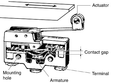
A Basic Switch is a compact, snap-action switch with micro-size contact distances and a contact mechanism that performs switching operations with the specified movement and force covered by a case that is equipped with an actuator on the outside.
Question
What causes load short-circuiting and what can be done about it?
Answer
Cause: The power supply may short-circuit because the loads are connected to different poles.
Countermeasure: Connect the loads on the side of the same pole.
Question
What causes insulation to deteriorate and what can be done about it?
Answer
Cause: Contact material is scattered around because of arching due to excessive load capacity.
Countermeasure: Switch the load using a contactor rather than switching a load directly using a switch.
Cause: Many water drops may have penetrated the Switch due to severe changes in the ambient temperature at high temperatures. Liquid may have penetrated the Switch and carbonized due to arc heat.
Countermeasure: Remove the cause, install the Switch in a box, or used a Sealed Switch.
Can I use AP-DV Drip-proof Terminal Cover mounted on Z-[]-B Basic Switches?
AnswerNo, you cannot use it with Z-[]-B because AP-DV Drip-proof Terminal Cover is only for Z-[]55-B5V.
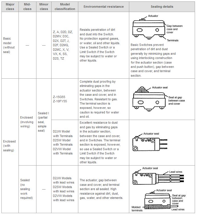
What is the protective structure?
1. The protective structure protects the Switch from penetration by human bodies, solid foreign objects, dust, water, or oil. The degree of impermeability is increased by encasing or sealing the Switch so that it can be used in environments subject to dust, water, or oil.
2. The extent of this ability is expressed as the degree of protection. The degree is expressed with the protection characteristic code IP-[][].
3. Standards IEC 60529: Defines degrees of protection against penetration of solid foreign objects and water. JEM 1030: Defines degrees of protection against oil.
I want to know the causes and solutions of contact failure.
Dusts adhere to the switch.
Remove the dusts. Alternatively, put the switch in a case or use a seal switch.
Insulating films are produced on the contact surface due to hazardous gas around the switch or switching in a low load area.
Replace the switch with a one containing environmentally-resistant contact materials. (gold, alloyed metal, etc.)
Soldering flux penetrates the switch.
Review the soldering method and use a switch that flux does not penetrate.
The input is not entered into the Programmable Controller when the switch is pressed. Why is this?
Programmable Controller DC inputs are generally 12 to 24 VDC at a few milliamps. The rated current for general-purpose Basic Switches is 5 to 10 A. Contacts use silver. Sulfide gas and oxidizing gas in the atmosphere form an insulating film on the silver contact surfaces, which results in contact failures. Use Microload Basic Switches that use gold alloy contacts.
Example: Z Basic Switch
Standard model: Z-15GW22-B, Microload model: Z-01HW22-B
The load does not turn ON when the Switch is pressed. Why is this?
Causes:
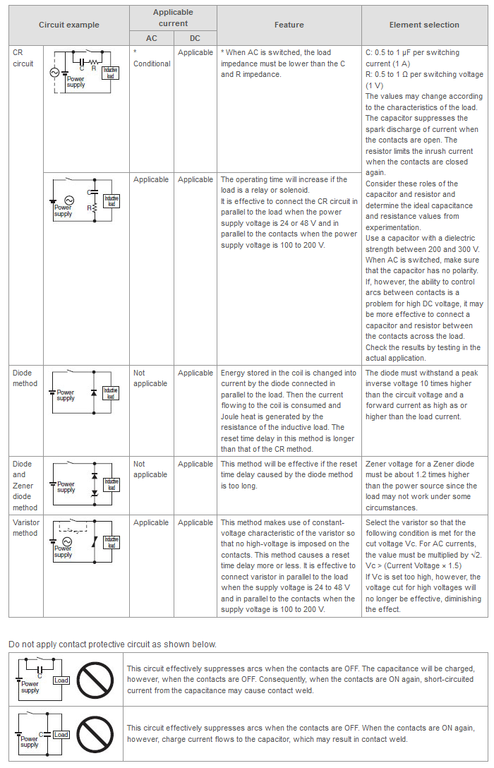
What causes contact welding and what can be done about it?
Are there Basic Switches available that can be used in locations subject to water?
Use a Drip-proof or Sealed Basic Switch.
Applicable models: Z-[]55 Drip-proof Basic Switch
Sealed Basic Switches: D2HW, D2VW, D2SW, D2JW
Which Basic Switches are suitable as door switches?
Hinge roller models are suitable.
Example: Z-GW22 Basic Switch
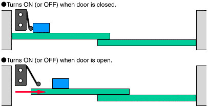
Note:Push the actuator to approximately 70% to 100% of standard OT.
Note:When the door is closed, the slant of the dog is the first place that the actuator roller contacts.
D-type, Q-type, and S-type Pushbutton Models can also be used for the actuator.
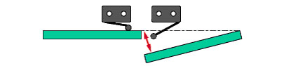
Note:Push the actuator to approximately 70% to 100% of the standard OT.
D-type, Q-type, and S-type Pushbutton Models can also be used for the actuator.
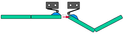
Note:Push the actuator to approximately 70% to 100% of the standard OT
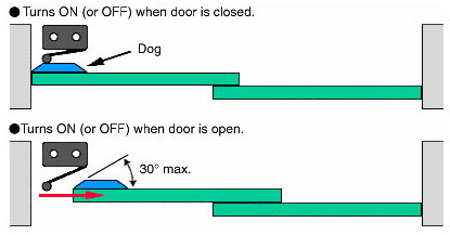
Note:The dog concept is the same as in Sliding Door 1, above.
The load will not turn OFF. Why is this?
The Switch contacts may be welded.
The contacts occasionally open when they are in contact. Why is this and what can be done about it?
Cause: The contacts open because of vibration or shock.
Countermeasure: Replace the Switch with a Switch that has greater contacting force (generally a Switch with a large OFF).
What is an actuator of Basic Switches and Limit Switches?
An actuator is part of a switch that is subjected to an external force, transfers that force to an internal spring mechanism, and moves contacts to perform switching. It is referred to as a push button or lever.
What is snap-action?
Snap action is a mechanism that enables a movable contact to quickly travel from one fixed contact to another fixed contact regardless of the speed at which the Switch is operated.
The high switching speed shortens the time arcing is maintained.
Contact wear and damage are reduced, so stable characteristics can be obtained.
Large-capacity switching can be performed with compact models.
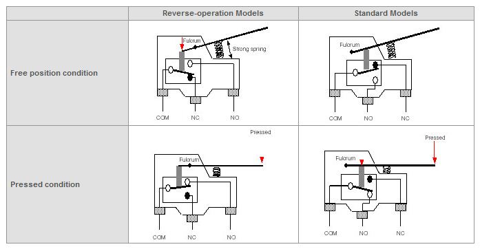
What type of operation does the reverse-operation Z-15GM[][] Basic Switches perform?
As the following figure shows, the Actuator fulcrum is in a different position from that of the standard Switches, so the internal movement is reversed.
Even in the free position, the pin plunger is continuously pressed by the repelling force of the strong, compressed coil spring, making reverse-type models highly vibration and shock resistive.
What is the degree of protection of Drip-proof Z-series Basic Switches?
The degree of protection is IP62 for the operation unit of Drip-proof Z-series.
The following apply for the terminals:
Do you have a Basic Switch or Limit Switch with DPST-NO/DPST-NC contacts?
Yes, the D4A-4[][][]N General Purpose Switch is a 4-contact DPDT double-break Limit Switch. The D4F-3[][]-[][] Series Safety Limit Switch of Small Safety Limit Switches also has DPST-NO/DPST-NC (slow-action) contacts.
And the DZ Basic Switch features DPDT contacts.
What is a maintained contact in the Z-series Basic Switches?
Switches with a maintained contact have a reset button at the bottom of the switch case in addition to the pushbutton (plunger) located on the opposite side of the reset button. Use the reset button to reset the switch.
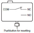
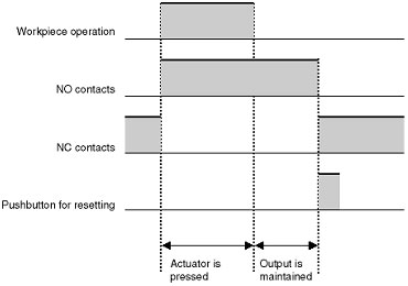
Because Switches have greater overtravel than pretravel, it is suitable for use in reversible control circuits, manual reset circuits, safety limit circuits, and other circuits that are not suitable for automatic resetting.
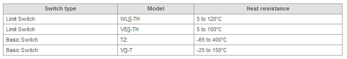
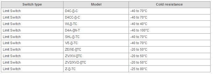
Are there any Basic Switches or Limit Switches that can be used at high or low temperatures?
Yes, the models in the following table can be used at high or low temperatures. However, not all models are necessarily available even though the model number legends give them.
Are there high-humidity models of Basic Switches available?
There is no definition of high-humidity processing for Basic Switches, so OMRON does not make such switches. Use standard models.
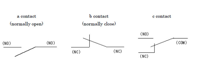
What relation is there between NO, NC, COM contact terminals and contact structures of the contact point a, b, c?
NO terminal, NC terminal and COM terminal represent contact terminals' symbols. Each symbol means a single terminal itself: Normally Open terminal, Normally Closed terminal and Common terminal respectively.
On the other hand, contact point a, contact point b and contact point c represent contact structures. Each means the combination of two contact terminals or more, and is also described as Make contact point, Break contact point and Transfer contact point respectively. When the contact structure has a single combination of the contact point a, it is called contact point 1a, and when it has two combinations of the contact point a, it is called contact point 2a.
Regarding the relation between contact terminals and contact structures, the contact point a is composed of two NO terminals, the contact point b is composed of two NC terminals, and the contact point c is composed of a single NO, NC and COM terminal. Therefore, the contact point 1c can be used as either contact point 1a or contact point 1b, but cannot be used as contact point 1a1b. This is because the contact point 1c has a COM terminal on one side, and thus it cannot be separated.
Sometimes the contact point a is called NO contact point, and the contact point b is called NC contact point, however, the JIS C 0301 Graphical Symbols for Diagrams prescribes them as contact point a and contact point b respectively.
Refer to the following diagrams which describe the contact point symbols conforming to the JIS C0301 Series 1. Be aware that such symbols as "NO" are not included in the contact point symbols, but are shown just for purposes of illustration.
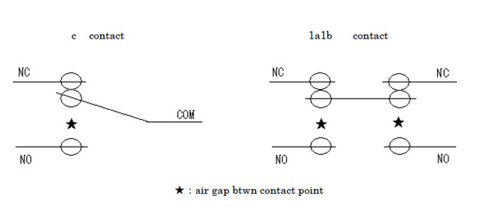
What relation is there between the contact spacing and the contact switching capacity?
If the contact spacing (contact gap) is large, the contact points can facilitate extinction of arc current which is generated when contact points open. Accordingly larger the contact spacing becomes, higher the current interrupting capacity of contact points becomes. Also, suppression of arc generation by accelerating the contact transfer rate can make the current interrupting capacity higher.
In general, as for the current of contact switching capacity, the influence of current interrupting capacity is greater than that of current carrying capacity, thus a high current interrupting capacity means a high current of contact switching capacity.
Additionally, as for the voltage of contact switching capacity, larger the contact spacing becomes, higher the voltage of contact switching capacity becomes.
Therefore, it is fair to say the contact spacing is basically proportional to the contact switching capacity.
Furthermore, as for the types of contact structures, the contact point c structure including Micro Switches and Hinge Type Relay, and the contact point 1a1b structure including large Limit Switches and Plunger Relay are available. As shown in the following diagrams, the contact point c structure has a single contact gap, while the contact point 1a1b structure has two contact gaps. Thus, the latter has a higher current interrupting capacity and is more suitable for switching with a large-capacity load than the former.
What is Contact Switch? What features does it have?
The term of Contact Switch is used compared to the Semiconductor Switch. The Contact Switch performs the switch function by mechanically switching contact points. Since the semiconductor has no contact points, the Semiconductor Switch is also called "Non-contact Switch" compared to "Contact Switch". The products adopting the Contact Switch include the Micro Switch, Limit Switch and Electromagnetic Relay. On the other hand, the products using the Non-contact Switch include the Solid State Relay (SSR).
As for the features of the Contact Switch, its advantages over the Non-contact Switch are: enhanced input and output separation, low output ON resistance and high output OFF resistance, high over-voltage and over-current protection, relatively low price; while its disadvantages are: high electric noise generation when switching the contact points, limited switching life of the contact points, chattering occurred by mechanical vibration and shock.
How do you choose the correct Basic Switch?
The ratings and all specifications have to be considered before making the final selection, but the main points are the Switch size, the maximum operating current of the contact, the operating force, the actuator type, and the degree of protection.
First, choose a Switch size that can be mounted in the desired equipment. You can select from among Z-size General-purpose Basic Switches, V-size Miniature Basic Switches, S-size Subminiature Basic Switches, J-size Ultra Subminiature Basic Switches, and Special-purpose Basic Switches. Z-size General-purpose Basic Switches are available as an X-model direct-current switch with magnetic blowout, a DZ-model DPDT Basic Switch for controlling two independent circuits, and a TZ-model high-temperature Basic Switch for operation up to 400°C. V-size Miniature Basic Switches are available in a D2MC-model low-torque Basic Switch with rotary-action operation. Special-purpose Basic Switches are designed for specific applications, so they are limited to use, for example, as power switches for doors.
Next, select the maximum operating current of the contact based on the load to be switched. You can choose a model with a maximum value of 3 A to 21 A for large-capacity loads, a maximum value of 1 A for medium-capacity loads, or a maximum value of 0.1 A for microloads. This selection is necessary because contacts have appropriate current ranges. The maximum operating current of the contact is roughly proportional to the Switch size, so it is sometimes automatically determined by choosing the size.
The operating force and actuator type should be selected according to the mechanism and structure of the machine or device that will operate the actuator of the Basic Switch. There are two or more operating forces that you can choose from for each model. Some actuators are an integral part of the Basic Switch, and others, such as those in the Z-size General-purpose Basic Switches and V-size Miniature Basic Switches, are purchased separately. Note that the operating force is roughly proportional to the Switch size, so it is sometimes automatically determined by choosing the size. Also, larger-size Switches have a larger number of actuator types available.
Select the degree of protection by considering the environment in which the Basic Switch will be used. The degree of protection for most models is IP00, but there are also IP67 sealed models for the V-size Miniature Basic Switches, S-size Subminiature Basic Switches, and J-size Ultra Subminiature Basic Switches. The Z -model drip-proof degree of protection is equivalent to IP62.
When you have come up with an actual model number, confirm its ratings and other specifications to make your final decision.
How can I convert grams (g) for force in the operating characteristic to Newtons (N)?
Use the following formula to convert kgf (kilogram-force) to N (Newtons):
1 kgf = 9.80665 N
Therefore, 1 N is equivalent to approximately 102 g.
1 gf to 1/102 N
Example: 140 gf to 1.37 N
The unit for force in the operating characteristics for switches was previously expressed mainly in gram-force (g-f). Presently, however, the unit Newtons (N) is used under the new Japanese Measurement Law that went into force in 1992.
 Automation Systems
  Motion & Power Solutions
  Safety, Vision and IDENT
  Sensing Solutions
  Control Components
  Switching & Accessories
  Switchgear and Trolley Systems
  Process Weighing
  LED Lighting
  Omron
Omron
 Mitsubishi
 Delta
Delta
 Autonics
 Inno
Inno
 Honeywell
 Novotechnik
 Orientalmotor
 Microscan
 IPA
IPA
 Technomech
 Intech
 IOT & Traceability
 Project & Panel Engg.
 Application Case Studies
 Solutions by Industry
 Solutions by Process
 Solutions by Product
 Corporate Information
 Company Profile
 Quality Policy
 Mission Statement
 Chairman's Message
 Intech Group Companies
