Frequently asked questions and answers for Counters - Industrial Automation
Which is priority given to the Timer's and Counter's reset input or signal (start) input?
The reset input has priority.
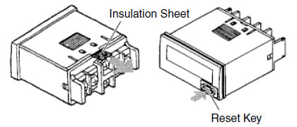
Why is the display blank on a newly purchased H7E[]-N?
An insulation sheet has been inserted to protect the display in case the Counter is stored for a long time without use.
Remove the insulation sheet and press the Reset Key on the front of the Counter before use.
When a single pulse only is input in the Counter, why does the Counter convert the pulse into at least two count values?
The following two causes may be causing in this problem.
1. The maximum counting speed setting is set to high-speed response and the Counter may be receiving relay chattering, bouncing, or noise input.
Countermeasure:
Set the maximum counting speed to as lower speed.
2. If the Counter has a prescaling function, the prescale value may be set.
Countermeasure:
Check whether the prescale value is set.
Why is the top section of the display not showing on the H5CN-[][][]M/H7CN-[][][]M Counter?
If a power interruption to the Counter occurs for 10 minutes or longer with the battery disconnected, errors will occur in the count value and display, even if the power recovers. Make sure a battery is connected to the Counter if the model has the suffix -M (backup function for power interruptions)
Any battery supplying 3 V can be used, but the data backup time depends on the capacity of the battery.
What do the input conditions that are specified in the catalog for "voltage input" mean?
Example: Using an H7E[]-NV
High (logic) level: 4.5 to 30 VDC
Low (logic) level: 0 to 2 VDC (input impedance: approx. 4.7 kΩ)
This refers to the voltage level at which an input turns ON. If a voltage of 4.5 VDC or higher is applied as a voltage input signal across terminals 1 and 2 for the count input and across terminals 3 and 4 for the reset input, the voltage can be read as an input signal.
This refers to the voltage level at which an input turns OFF. When the input is a two-wire input or an SSR (Solid State Relay), the leakage current when the input is OFF will cause residual voltage across terminals 1 and 2 for the count input and across terminals 3 and 4 for the reset input.
A voltage of 2 V or lower is detected as an OFF signal.
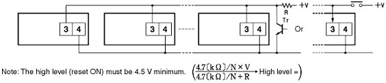
What should I be aware of when connecting inputs to H7E[]-N Total/Time Counters in parallel?
Be aware of the following points when connecting the count, timer, and reset inputs in parallel. Connecting a diode to prevent the reverse flow of current is particularly important for no-voltage input model.
Example: Reset Input to H7E[]-N
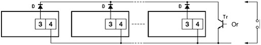
Note:
1.The leakage current of the transistor used for input must be less than 1 µA.
2.The forward voltage of the diode must be as low as possible (i.e., 0.1 V maximum with an If of 20 µA) so that the voltage between terminals
3 and 4 will be the specified value of 0.5 V when the reset input is ON.
Why does the Counter not count when the input signal is input?
1. The input mode and actual input may not match.
Example:
If an encoder input is used, check whether the input mode is set to Up/Down (incrementing/decrementing) C mode.
2. If the maximum counter speed is set to low speed, the pulse may be shorter than the minimum input width, preventing the Counter from counting the input. Match the maximum counting speed to the actual input width.
3. A no-voltage signal may be input to a voltage-input model.
Replace the input device with a voltage output model, or connect an external resistor if using input from an open collector.
The following diagram shows an example using the H7AN.
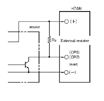
*Please set the input signals to "H (High)" levels, for the open-collector in the sensor to be turned off.
Why does the Reset Key on the H7E[]-N not function?
Is the Key Protect Switch set to ON?
The Key Protect Switch is used to prohibit key operations, thereby preventing incorrect operations.
If the Key Protect Switch is ON, key operations are prohibited and the Counter cannot be reset. To enable key operations, set the Key Protect Switch to OFF.
What are the voltage values when the input terminals used for an NPN open-collector input are OFF and the current values when the input terminals are ON for the H7BR, H7HP, and H7EC Counters?
The following currents and voltages can be switched.
What do the input conditions that are specified in the data sheet for "no-voltage input" mean?
A no-voltage input is a count input from the open collector of a transistor or from a contact to the input terminal.
Example: Using the H7EC-N
Maximum short-circuit impedance: ON at 10 kΩ max.
Short-circuit residual voltage: 0.5 V max. (actual power: 1.0 V)
Minimum open impedance: OFF at 750 kΩ max.
(1) Contact Input (from a Relay or Switch Contact)
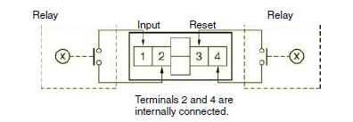
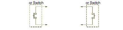
Figure 1. Contact Input
Note: Use Relays and Switches that have high contact reliability because the current flowing from terminal 1 or 3 is small. OMRON's Solidstate Relay the G3TA-IA/ID should be recommended for the SSR use.
(2) Transistor Input (from an Open Collector of an NPN Transistor)
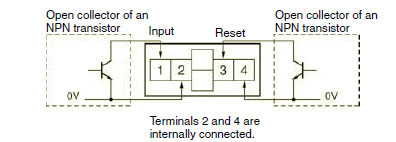
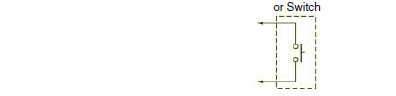
Figure 2. Transistor Input
Note 1: The residual voltage in the output section of Proximity Sensors or Photoelectric Sensors is small (less than 0.5 V) because the current flowing from terminal 1 or 3 is small, thereby allowing easy connection.
Note 2: Select transistors (Tr) according to the following formulas:
Dielectric strength of the collector ≥ 50 V
Leakage current < 1μA
This term refers to the resistance value that is used to detect when the input to the Counter is ON.
(In figure 1, the input is detected as ON when the resistance value between terminals 1 and 2 is 10 kΩ max. when the input is turned ON.)
3. Short-circuit residual voltageThis term refers to the voltage that remains in both transistor terminals when an input turns ON. (See Figure 2.)
When using the H7EC-N, the short-circuit residual voltage is 0.5 V max (actual power: 1.0 V), so select a model with a residual voltage (voltage drop when output is turned ON) of 0.5 max, for the input device in figure 2.
Note:If the residual voltage is the same as the specified voltage or higher, ON signals can not be detected, preventing normal operation.
This term refers to the resistance value used to detect whether the input is an OFF signal.
If the impedance of the input device is the same as the specified value or lower, the OFF signal will not be detected and the input will remain ON, resulting in abnormal operations.
Can the batteries of the H7E[]-N be replaced?
Yes.
Applicable Battery: Y92S-36.
Which Counter/Timer models do use a memory backup function for power interruptions (EEPROM) that do not use a battery?
Counters: H7CX, H8GN, H7HP, H7GP
Timers: H5CX
These models write the required data to EEPROM when the power supply voltage is turned OFF.
The number of times that EEPROM can be written (i.e., the number of overwrites), however, is limited.
Which Relays are compatible with the H7EC-N and H7ET-N Counters that use no-voltage input?
Recommended model: OMRON Solid-state Relay the G3TA-IA/ID
Which Relays are compatible with the H7EC-N and H7ET-N Counters that use no-voltage input?
Recommended model: OMRON Solid-state Relay the G3TA-IA/ID
What is "Batch counting"?
Example:
The batch counting function in the H7BR-B can be used to turn ON the batch output for the preset number of batches.
The following diagram shows an example when using a repetitive operating mode (e.g., C mode) to output a packing signal as the OUT output and pack five items in one packing case.
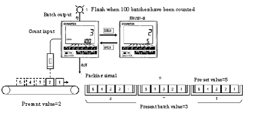
To light the indicator when 100 cases have been packed (preset value (5 units) × 100 cases), set the batch counter set value to 100 and start operation. The batch output will turn ON until the target is reached.
Turn ON the batch count reset input to reset the batch output and batch count display.
Part of the display of the timer or counter is already dark even though we just made the purchase. What's the problem?
It might be the effects of static electricity.
Wait for a minute to see what happens.
If the problem persists for more than a few minutes, consult with your nearest OMRON representative.
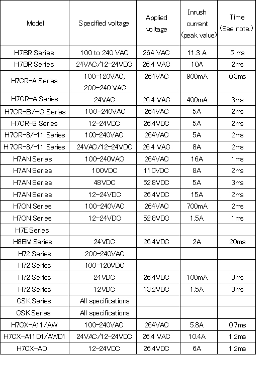
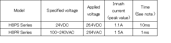
What is the inrush current for Counters?
Using the H7BR, which has a current of approximately 10 VA (for 240 VAC, 50 Hz), as an example, an inrush current of approximately 8 A continues for approximately 2 ms when the power is turned ON.
If the Countera's power supply is turned ON/OFF with a transistor, the inrush current may damage the transistor.
Refer to the following table of inrush currents (reference values).
The blank spaces in the table indicate inrush currents that have been omitted because they are close to the steady-state current.
The values shown in the table are approximate values and should be used for reference only.
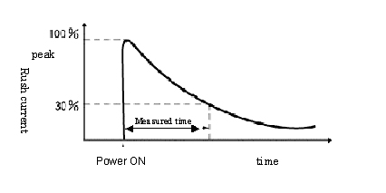
Note: The inrush current time is measured in the wave range shown in the following figure.
What Preset Counter models are available?
Refer to the following selection guide
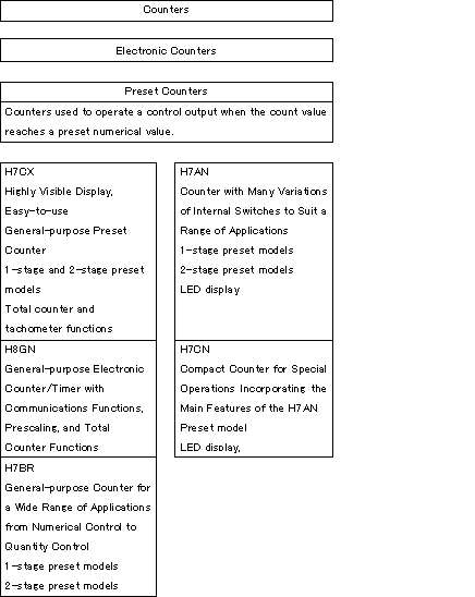
What is a Preset Counter?
A Counter used to operate a control output when the count value reaches a preset numerical value.
What is a Total Counter?
Total Counters display the count value only and are not provided with control outputs.
What is a substitute product for old H7EC Total Counters?
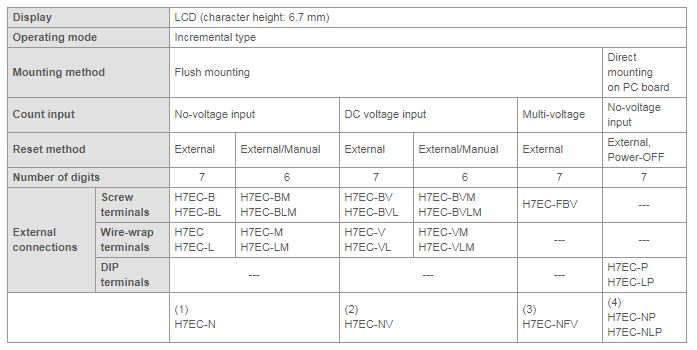
Note:
1.Model numbers with "L" have a maximum counting speed of 30 Hz (cps). Other models are 1 kHz (cps). Only the models with a 20-Hz maximum counting speed have multi-voltage inputs.
2.The bottom row gives recommended substitute products or models with substitute functions. For details, refer to the following information.
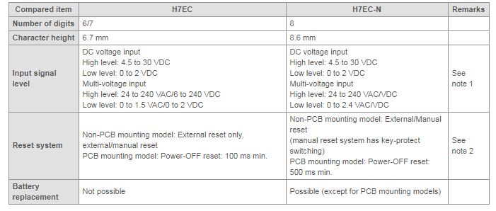
Note:
1.The high level 6 to 24 VDC of H7EC-N is cut, so choose a DC voltage input model.
2.Be careful when using the power-OFF reset.
What is a substitute product for old H7ET Time Counters?
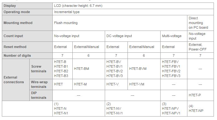
Note:
1.Discontinued models with no number indicate that the time is displayed in hours. Models with the suffix "1" indicate that the time is displayed in hours, minutes, and seconds. The suffix "2" indicates hours and minutes, and the suffix "3" indicates days and hours.
2.The bottom row gives recommended substitute products or models with substitute functions. For details, see the following information.
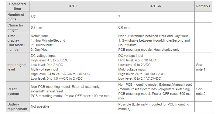
Note:
1.The high level 6 to 24 VDC of H7ET-N is cut, so choose a DC voltage input model.
2.Be careful when using the power-OFF reset.
What are Time Counters?
Time Counters measure time and display the amount of time that has been measured. They are also called total time meters or hour meters. Hours is not the only unit available, however, and time can displayed in minutes, seconds, or in some cases even days.
Time Counters are not Timers. You set a specific time with Timers and an electrical signal is output when that time has elapsed. With Time Counters on the other hand, you do not set a time. They simply total the time and display that total. If you were to define the two in terms of timers, then Timers would be Preset Timers and Timer Counters would be Total Timers. Time Counters, however, have historically been classified as Counters.
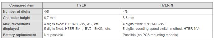
What is a substitute product for old H7ER Tachometers?
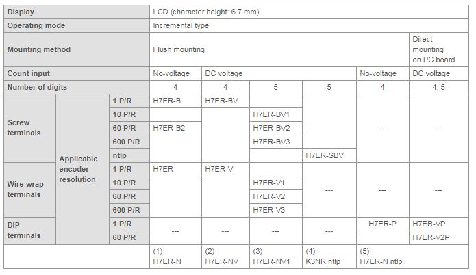
Note:
The bottom row gives recommended substitute products or models with substitute functions. For details, refer to the following information.
What are the differences between using a lithium battery and EEPROM for storing Digital Timer and Counter data when a power interruption occurs?
What are the differences between using a lithium battery and EEPROM for storing Digital Timer and Counter data when a power interruption occurs?
Power-interruption memories are available for motor-type timers and electromagnetic counters using mechanical methods, and their counterparts are available for electronic Timers and counters using a lithium battery and EEPROM.
The main differences between the two methods are as follows: With a lithium battery, the internal control circuit and display circuit are constantly backed up by the power of a lithium battery, whereas with an EEPROM, the necessary data is written to EEPROM when the power is interrupted.
Because the lithium battery has a service life of approximately 10 years, the power-interruption memory function stops when the battery reaches the end of its lifetime. However, the other functions in the Timer or Counter can still be used just as they are. Also, though the lithium battery cannot be replaced in Timers and Counters for which the replacement procedure is not specified, the battery can be replaced at the factory for all models presently in production. When replacing the battery, it is best to also consider replacing other parts, particularly the LCD, because these parts have a limited lifetime as well.
With an EEPROM, the EEPROM has a lifetime of approximately 100,000 writes and a data retention capability of approximately 10 years. The data retention capability poses no problems in actual use, but when considering the write life, particularly for Timers, applications with few power supply breaks are preferred. In other words, signal startup is preferable over power-supply startup.
Another difference is that because a lithium battery is a back-up method, function parameters can be set using front-panel keys, with no power supply necessary. This is not possible with EEPROM. In both methods, the function parameters can be set using DIP switches or a similar method, with no power supply necessary.
What is a substitute product for old H7A Digital Counter?
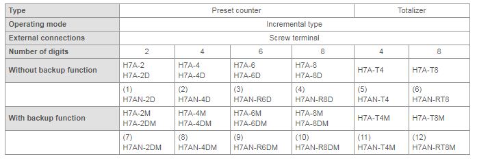
Note:
1.Preset Counters without "D" do not display the present value. Models with "D" have number displaying functions. The recommended substitute products all have number displaying functions.
2.The bottom row gives recommended substitute products or models with substitute functions. For details, refer to the following information.
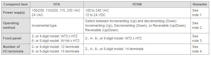
Note:
1.There is no substitute product for the 24 VAC model because there are no 24 VAC H7AN models. Step up the voltage with a transformer and use 100 to 240 VAC model or see whether 24 VAC/12 to 24 VDC H7BR Digital Counters can be used.
2.H7A is an incrementing counter. For H7AN 2-digit or 4 digit counter, set the UP-DOWN switch to UP, and for H7AN 6-digit or 8-digit counter, set the counting function selector to UP. These are the default settings.
3.The panel cutout for the front panel with dimensions W72, H72 are compatible.
4.Be careful because the terminal numbers are not compatible.
When inputs CP1 and CP2 are simultaneously input to H7CX Multifunction Preset Counters when used as a dual counter, are both of them counted?
Yes, they are both counted.
Example: CP1 PV = 10, CP2 PV = 5
Simultaneous input of CP1 and CP2 results in CP1 CV = 11 and CP2 PV = 6.
The dual count value after addition is CP1 PV + CP2 PV, therefore 11 + 6 = 17.
Example: CP1 PV = 10, CP2 PV = 5
Simultaneous input of CP1 and CP2 results in CP1 CV = 11 and CP2 PV = 6.
The dual count value after subtraction is CP1 PV - CP2 PV, therefore 11 - 6 = 5.
The rate of rotation is displayed using the H7CX's tachometer function, but why doesn't it show 0 when rotation has stopped?
Only the following two H7CX-series models can be used as tachometers.
H7CX-R tachometer
H7CX-AW Multifunction Preset Counter/Tachometer
Adjust the auto-zero time.
The default auto-zero times for each model are as follows:
H7CX-R: 999.9S
H7CX-AW: 99.9S (when used as Tachometer)
Example: A machine that outputs 1 pulse per revolution is rotating at 30 revolutions per minute. The revolutions can drop to 10 revolutions per minute.
30 revolutions per minute (30 rpm) indicates that
60 (seconds) ÷ 30 (revolutions) = 2 (seconds per revolution)
Therefore a pulse is normally input every 2 seconds.
When the rate of rotation falls to 10 revolutions per minute (10 rpm),
60 (seconds) ÷ 10 (revolutions) = 6 (seconds per revolution)
Therefore the pulse interval becomes 6 seconds.
If the auto-zero time is set to 6 seconds, it waits for the next pulse for 6 seconds, and then displays the speed at that time (e.g., 10 rpm). If there are no more inputs, the auto-zero function is activated and the display becomes zero.
If the pulse interval is longer than the auto-zero time, the auto-zero function is activated and the display becomes zero.
Applicable models: H7CX-R and H7CX-AW
When the H7ET-N's Time Counters time range switch is set to 0.0 to 3999d23.9h, what is displayed after 23.9 h?
100.0 will be displayed after 23.9.
100.0 signifies 1 (day) and 00.0 (hour).
For example, one day and 1.0 hour would be displayed as 101.0.
Supplementary Information
0.1 h indicates 6 minutes.
Therefore, 0.0 will be displayed between 0 to 5 minutes, and 0.1 will be displayed after 6 minutes.
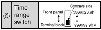
Note:
1.Set the switches before mounting the Unit to a control panel.
2.If the counting speed setting is changed, the present value will not be held. Press the Reset Key on the front panel.
The time unit is given in the datasheet and in the figure above, but on the actual device it will not be displayed. Instead, unit labels (-hours/-d-h/-h-m/-h-m-s) are provided.
 Automation Systems
  Motion & Power Solutions
  Safety, Vision and IDENT
  Sensing Solutions
  Control Components
  Switching & Accessories
  Switchgear and Trolley Systems
  Process Weighing
  LED Lighting
  Omron
Omron
 Mitsubishi
 Delta
Delta
 Autonics
 Inno
Inno
 Honeywell
 Novotechnik
 Orientalmotor
 Microscan
 IPA
IPA
 Technomech
 Intech
 IOT & Traceability
 Project & Panel Engg.
 Application Case Studies
 Solutions by Industry
 Solutions by Process
 Solutions by Product
 Corporate Information
 Company Profile
 Quality Policy
 Mission Statement
 Chairman's Message
 Intech Group Companies
