Frequently asked questions and answers for Displacement and Measurement Sensor - Industrial Automation
Question
Can the ZX-L measure transparent objects?
Answer
Transparent objects, which allow light to pass through, cannot be measured because Reflective Smart Sensors use a PSD and Through-beam Smart Sensors use a PD. If the transparency and required accuracy are low, it might be possible to use the ZX-L for some applications. We recommend that you conduct tests with the actual object first. If the transparency and required accuracy are high, the following Sensors can be used to measure transparent objects.
CCDs enable detecting transparent objects.
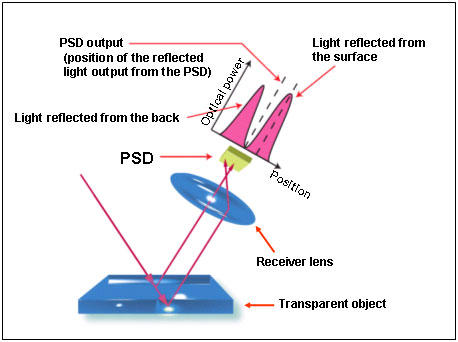
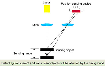
A Regular Reflective Sensor that uses a PSD cannot distinguish the light reflected from the surface because it is affected by the light reflected from the other side of the object and/or the background. For this reason, displacement of the surface cannot be accurately measured. A Diffuse Reflective Sensors cannot make measurements because the diffused light is too small.
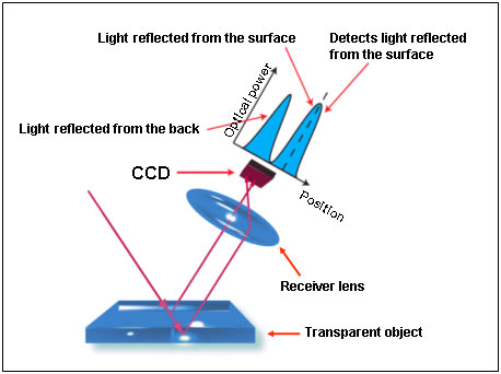
A Regular Reflective Sensor with a CCD can extract the light reflected from the surface because it can distinguish between the light reflected from the surface and the light reflected from the other side. For this reason, displacement of the surface can be accurately measured without being affected by the light reflected from the other side and/or the background.
The above Sensors can detect the edge of transparent objects by using a CCD in transparent object detection mode.
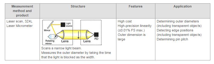
The above Micrometers can be used to detect the outer diameter or edge position of transparent objects using a laser scan method as the measurement principle.
Question
What is the maximum length of a cable connected to the Laser Measurement Sensors, Smart Amplifier "ZX-L"?
Answer
For Reflective Type Sensor Head: 20.6 m (Cable length when shipped from the factory 0.6 m + extension 20 m)
For Through-beam Type Sensor Head: 10.1 m (Cable length when shipped from the factory 2.1 m + extension 8 m)
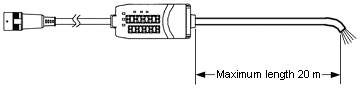
For Amplifier Unit: 20 m (Cable length when shipped from the factory 2 m + extension
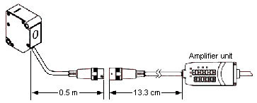
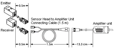
Pull-out length of a cable connected to the Reflective Type Sensor Head when shipped from the factory is 0.5 m.
Thus, in the case of the Reflective Type Sensor, secured length of a cable between the Sensor Head and the Amplifier Unit is 0.5 m + 13.3 cm = 63 cm when shipped from the factory.
Pull-out length of a cable connected to the Through-beam Type Sensor Head when shipped from the factory is 0.5 m, and a 1.5 m-long Y-shaped bifurcated Sensor Head - Amplifier unit Connection Cable is included with shipment. Thus, in the case of the Through-beam Type Sensor Head, secured length of a cable between the Sensor Head and the Amplifier Unit is 0.5 m + 1.5 m + 13.3 cm = 2 m 13 cm when shipped from the factory.
When the above mentioned cable connected to the Sensor Head is further extended than it is shipped from the factory, be sure to use the following Extension Cable "ZX-XC Series".
Optional
ZX-XC1A (Cable Length = 1 m)
ZX-XC4A (Cable Length = 4 m)
ZX-XC8A (Cable Length = 8 m)
ZX-XC8A (Cable Length = 9 m)
ZX-XC8A (Cable Length = 9 m)
When a cable connected to the Reflective Type Sensor Head is extended up to 20.6 m, use the following cables in combination.
Length of a cable connected to the Sensor Head when shipped from the factory (0.5m) + 13.3 cm + ZX-XC9A (Cable Length = 9 m) × 2 + ZX-XC1A (Cable Length = 1 m) × 2 = 0.5 m + 13.3 cm + 18 m + 2 m = 20.6 m
When a cable connected to the Through-beam Type Sensor Head is extended up to 10.1 m
Length of a cable connected the Sensor Head when shipped from the factory (2 m)+ 13.3 cm
+ ZX-XC8A (Cable Length = 8 m) × 1
= 2 m + 13.3 cm + 8 m
= 10.1 m
Length of a cable connected to the Amplifier Unit when shipped from the factory is as follows.
ZX-LDA11 (Cable Length = 2 m, NPN Output)
ZX-LDA11 (Cable Length = 10 m, NPN Output)
ZX-LDA41 (Cable Length = 2 m, PNP Output)
When the above mentioned cable connected to the Amplifier Unit is further extended than it is shipped from the factory, be sure to use the same type of shielded cables (shield specifications for the Amplifier Unit: 0.1 mm in diameter, 51 shielded wires).
The threshold value cannot be set. What is causing this, and what can be done to resolve it?
Cause 1:
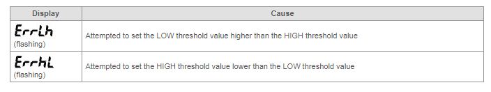
The HIGH threshold value is set lower than the LOW threshold value.
In this case, the following error message will be displayed.
Remedy 1:
Make sure that the HIGH threshold value is set higher than the LOW threshold value.
Cause 2:
The hysteresis (Hys) is too high. If this is the case, the difference between the HIGH threshold value and the LOW threshold value is smaller than the hysteresis value, so that a PASS judgment is not possible. The setting is thus not allowed.
Remedy 2:
Make the hysteresis value smaller to avoid the condition described above.
How many times can the zero reset be used?
The zero reset can be used up to approximately 100,000 times. This is because the default setting specifies that every time the zero reset is used, the zero reset value must be stored in internal memory. Therefore, when even when power is interrupted, the zero reset value will revert to the previous status set by the zero reset function when the power is turned ON again.
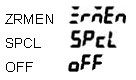
If there is no need to save the zero reset value, you can use the zero reset an unlimited number of times by going to FUN mode and setting (ZRMEN) under (SPCL) to (OFF).
Actual indications on a panel.
Can Sensor Heads with different measurement distances be used for calculations between adjacent Sensors?
No, the Sensor Heads must have the same measurement distances. If they have different measurement distances, the correct distance cannot be found.
What is displayed on the resolution display of channel 1 and channel 2 when performing calculations for adjacent Sensors?
The resolution display on the channel 2 Amplifier shows the resolution result of mutual calculations between channels 1 and 2. The resolution on the channel 1 Amplifier shows the resolution of only channel 1.
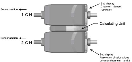
How many Sensors can be connected when performing calculations for adjacent Sensors?
Up to 2 Sensors can be connected.
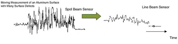
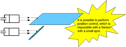
For what applications are the Reflective Line Beam Sensors most useful?
They are useful when making measurements by averaging, e.g., when irregularities in metal surfaces or diffuse reflection affects measurements. They are also effective when aligning the beam position is difficult, as it is for round bars.
Support Software "Smart Monitor" does not start properly. What is causing this, and what can be done to resolve it?
Check the following items.
1.Make sure that the Sensor Head is connected to the Amplifier Unit and that it operating properly.
2.Is the operating mode switch on the Amplifier Unit in RUN mode?
If it is in any other mode, the Smart Monitor will not operate properly.
3.Try resetting the Amplifier Unit or turning the power OFF and ON.
4.Is the connecting cable a D-sub 9-pin (female/male) cross cable?
5.If a USB-232C cable is used, make sure that the cable is not faulty.
6.Make sure that the connecting cable is connected properly.
7.Try reinstalling the "Smart Monitor".
8.Turn ON the power to the Sensor and then start the "Smart Monitor".
9.The "Smart Monitor" operation has been verified only with Windows 98 or Windows 2000. Are you using one of these?
10.Check the communications conditions. (The baud rate is fixed at 38,400 bps. Check that the COM port number is correct.)
11.Are other applications using the same COM port? (An error message saying that the communications port cannot be opened will appear.) If this is the case, set another COM port and restart the software.
*Windows is a registered trademark of Microsoft.
Is the timer function valid for all the HIGH, PASS, and LOW judgment outputs?
No, it is valid only for the PASS output.
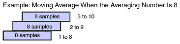
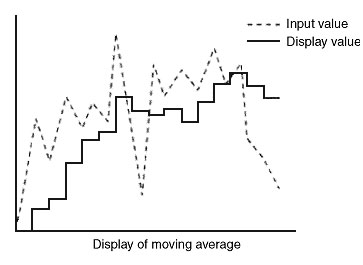
What is average processing (moving average)?
The average processing performed by the Smart Sensor uses a moving average. A moving average is an average where each time a sample is taken the average of the last n samples including the current sample is calculated and displayed. Therefore, the average is associated with the preceding data
The average processing performed by the Smart Sensor uses a moving average. A moving average is an average where each time a sample is taken the average of the last n samples including the current sample is calculated and displayed. Therefore, the average is associated with the preceding data.
Select the averaging number as required by the application
The averaging number of the Smart Sensor can be set to 1, 2, 4, 8, 16, 32, 64, 128, 256, 512, 1024, 2048, or 4096 samples.
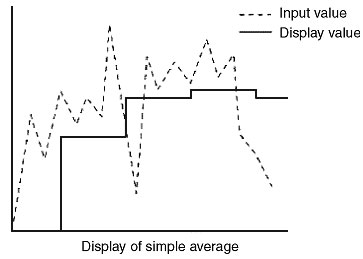
A simple average is shown below. (Remember, the Smart Sensor uses a moving average as described above, not a simple average.) You will be able to see the meaning (effectiveness) of the moving average by comparing it to a simple average.
A simple average takes n samples and calculates the average of those values. The display of the average remains the same until the next nth sampling is taken. It is simply the average of n samples so it has nothing to do with the previous data.
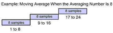
The output response is slower for simple average.
Is there a way to detect the deterioration of the LD laser diode?
When the power is turned ON, Lddwn* will appear on the sub-digital display of the Amplifier.

When this display appears, it means that the laser diode has deteriorated and the Sensor must be replaced. Only the Sensor of the Smart Sensor needs to be replaced. The Amplifier can still be used.
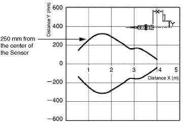
How far away must surrounding objects be for them not to affect E4PA Ultra Sonic Displacement/Measuring Sensor?
For example, if the sensing distance of the E4PA-LS400-M1 is set to 1 m, the following characteristics data shows that the spread of ultrasonic waves from the center of the Sensor is approximately 250 mm. This means that if there are objects within 250 mm, they will be detected. Leave ample space surrounding the Sensor. Place any object at least 375 mm away (1.5 times the minimum distance).
How long does the Laser Diode (LD) last?
The LD lasts for approximately 50,000 hours at 40°C with failure rate of 10%.
It lasts for approximately 100,000 hours at normal temperature (Approx. 25°C).
*Semiconductor laser is operates the pulse of one-fifth duty for keeping the long life.
*The life of Semiconductor laser becomes the approx. 50% by increasing the 10°C.
For your information, the Smart Sensors has the function of laser life degradation detection.
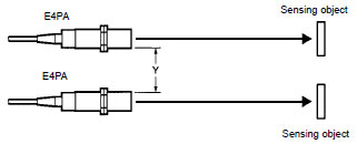
How far should E4PA Ultrasonic Sensor be separated from each other?
Separate the Sensors as specified in the following table when using two or more Sensors in close proximity to one another.
*Semiconductor laser is operates the pulse of one-fifth duty for keeping the long life.
*The life of Semiconductor laser becomes the approx. 50% by increasing the 10°C.
For your information, the Smart Sensors has the function of laser life degradation detection.
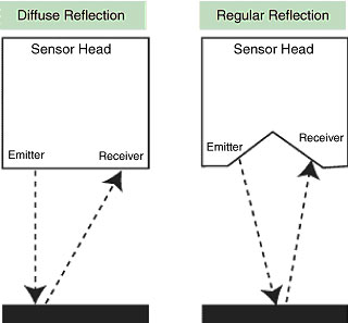
What types of reflection heads are available for each surface character of sensing objects?
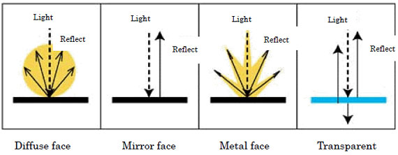
Since the surface is evenly rough, the light uniformly reflects diffusely, Reflecting Lights are uniformly distributed in all directions.
Reflecting lights are reflected at an equal angle to emitting lights. They are not reflected in other directions.
Regular Reflective Type Sensor Heads:
Defuse Reflection (Metal):
Recommended modelsZX-LD100L (Diffuse Reflective/ Line Beam Model)
ZX-LD300L (Diffuse Reflective/ Line Beam Model)
Transparent Body:
The following range of sensor heads is available for sensing the transparent body other than the Smart Sensors.
Sensor Heads for measuring the transparent bodyWhat sensing objects are hardly detected by the Ultrasonic Displacement Sensors and the Ultrasonic Sensors?
1. Since objects with extremely high sound absorbency (sound absorbing materials such as fresh snow and glass wool) do not produce reflected sound, they may not be detected.
2. Moving objects
(1) When detecting the liquid level which is waving or being agitated, the waving liquid level is directly detected.
(2) Objects moving at high speed (vehicle on expressway, motorcycle and etc.)
3. High-temperature objects
Surrounding air is heated so that ultrasonic waves may be reflected.
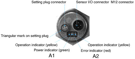
E4PA Ultra Sonic Displacement/Measuring Sensor A1 (power indicator, green LED) and A2 (error indicator, red LED) indicators flash alternately and the E4PA is not operating properly. What is causing this, and what can we do to resolve the problem?
1.The reflected sound wave is unstable.
2.The surface of the sensing object is not flat or the distance setting is near the maximum rated detection distance.
Countermeasure:1.Use the Sensor at a closer distance.
2.If you cannot move the Sensor any closer, use a Sensor that has a longer detection distance. For example, if the Sensor that you are currently using is the E4PA-LS400-M1 with a detection distance of 500 to 4,000 mm, then use a E4PA-LS600-M1 with detection distance of 800 to 6,000 mm instead.
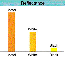
How are the gain switch functions AUTO, METAL, WHITE, and BLACK used in a Reflective Sensor?
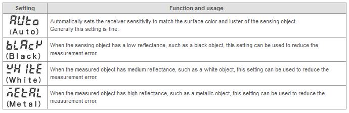
First of all test operation with AUTO. If the error is too large, try the other three settings as described above. The effectiveness depends on the sensing object, so always confirm operation with the actual system.
E4PA Ultrasonic Sensors will be used to detect liquid levels, but it is difficult to move E4PA up or down when installing it. Is there an easy way to set the distance?
Using E4PA with the default settings is recommended. The rated minimum distance and rated maximum distance are already set. Setup can be completed simply by setting scaling for analog values (setting desired values for analog values such as 4 to 20 mA) using Digital Panel Indicators.
The resolution, however, will be (Maximum distance - Minimum distance)/4096.
At the maximum sensing distance of the E4PA Ultrasonic Displacement Sensor, the output should be 20 mA but only 16 mA is output. What is causing this?
Liquid surfaces are not perfectly flat, therefore perfect reflection of the waves cannot be obtained. The linear output cannot reach its maximum value.
To use the Sensor at its maximum sensing distance (e.g., when the sensing range of the E4PA-LS400-M1, is 500 to 4,000 mm, the maximum sensing distance is 4,000 mm), the sensing surface must be perfectly flat and the waves must be vertical. Keep this in mind when positioning the Sensor.
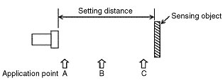
How much does wind affect E4PA Ultrasonic Sensor?
The Ultrasonic Switch uses air as the translation medium, so it is easily affected by wind. Care must be taken when using this Sensor but the E4PA is the least affected by wind out of all the OMRON Ultrasonic Sensors
For example, wind produced by a 50-cm industrial fan at the highest level will hardly change the analog output.
Effect of wind
Testing conditions: Temperature: 23.5°C, Humidity: 54%
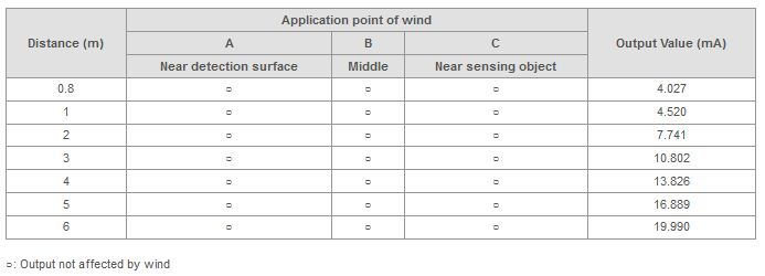
1.Initial setting is 0.8 M - 4 mA, 6 M - 20 mA for a flat board (standard sensing object).
2.Set the sensing object at each setting distance and turn ON the fan. Check if the output changes when wind is applied with the fan.
Power supply: 24 VDC
Sensing object: Flat board (standard sensing object), 100 x 100 mm
Fan: Industrial fan (50-cm diameter) strongest setting
What is the principle of regular reflection measurements?
When the distance of the sensing object changes, the position where the light is received on the receiver element changes. This change is converted into a displacement.

The laser light is emitted from the emitter lens towards the sensing object. The light that is reflected off the object is collected by the receiver and an image is formed on the PSD. If the distance of the sensing object differs, the image formed on the PSD varies. The two PSD outputs will change.
The ratio of these two outputs is found and then converted to a distance.
Compared to a CCD, a PSD is smaller, faster and can be produced at lower cost.
Smart Sensors (Laser Displacement & Measurement Sensors) Using Regular Reflection ZX-LD30V, ZX-LD30VL
The difference between the diffuse reflection method and the regular reflection method is described below.
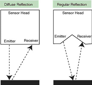
The diffuse reflection method collects the diffuse light reflected from the sensing object.
The diffuse reflection method gives stable measurements. It can be used even when the reflection angle variation is large. If the surface is shiny, the accuracy becomes low and it may not be able to make measurements.
The regular reflection method detects the object using regular reflection.
Accurate measurements can be made for shiny surfaces but it doesn't have a large tolerance for angle variance.
What is the principle of diffuse reflective measurements?
When the distance of the sensing object changes, the position where the light is received on the receiver element changes. This change is converted into a displacement reading.
The laser light is emitted from the emitter lens towards the sensing object. The light that is reflected off the object is collected by the receiver and an image is formed on the PSD. If the distance of the sensing object differs, the image formed on the PSD varies. The two PSD outputs will change.
The ratio of these two outputs is found and then converted to a distance.
Compared to a CCD, a PSD is smaller, faster and can be produced at lower cost
The difference between the diffuse reflection method and the regular reflection method is described below.
The diffuse reflection method collects the diffuse light reflected from the sensing object
The diffuse light method gives stable measurements. It can be used even when the reflection angle variation is large. If the surface is shiny, the accuracy becomes low and it may not be able to make measurements.
The regular reflection method detects the object using regular reflection.
Accurate measurements can be made for shiny surfaces but it doesn't have a large tolerance for angle variance.
Are there any precautions for using E4PA Ultra Sonic Displacement Sensor to detect the liquid level in a tank?
1.Make sure that the E4PA is far enough away from the walls.
2.If the upper part of the tank is narrow (cylindrical), expose the sensing surface or make it into a horn shape.
3.Make sure that there are no objects protruding into the operating range of the Sensor. (Otherwise the protruding object will be detected.)
Does the temperature of the sensing object affect the detection ability of E4PA Ultra Sonic Displacement Sensor?
A temperature compensation circuit is built into the setting plug, but the output value varies with the temperature of the sensing object and the ambient temperature.
(±1% FS of the output value at 23°C in the range of -10°C to 55°C.)
When the temperature of the sensing object exceeds 55°C, an air swirl is generated around the object. In some cases, this may cause a detection error.
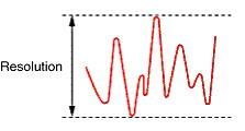
What is resolution?
The resolution is the width of the linear output variation when both the sensing object and Sensor are stationary. Even if both the sensing object and Sensor are stationary, the linear output value is not stable. It varies, and the width of this variation is the resolution.
The resolution is the ability to distinguish differences. It is used as the basis for judgments, but only a 10th of the required resolution is normally used. For example, if a resolution of 20 μm is required for a judgment, a Sensor with resolution capability of 2 μm should be used.
Caution:
The resolution does not represent the accuracy of the distance. It indicates reproducibility when positioning a sensing object. The resolution is defined for OMRON's standard sensing object (white ceramic), and depends on the type of sensing object.
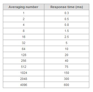
Relationship of Averaging Number and Response Time (with a Fixed Gain)
What does the "W-UP" display mean when the power supply for ZX-E Smart Sensors or ZX-T Smart Sensors or is turned ON?
It means the Amplifier is warming up. "This symbol"* will flash on the sub-display of the Amplifier while it is warming up

The display will return to normal when warming up has been completed. Settings can be made and measurements can be performed while the Amplifier is warming up. In that case, the normal display will appear instead of the warming-up display. Warming up itself, however, will not be completed, so high-accuracy measurements will not be possible. Also, ZX-L-N Laser type does not have this display function.
Can the Actuator's Measurement Head of D5V Contact Displacement Sensor be replaced?
The Actuator's Measurement Head of D5V cannot be replaced. The Flat Actuator, D5V[]-3F1, has an M2.5 screw so the Measurement Head can be replaced.
Models that have a replaceable Measurement Head are the D5SN-TN1, D5SN-TF1, and D5SN-TR1
When a command was sent using Z300 High-precision Laser Profiling System serial communications output, an error was returned. Why is this?
Because an error was returned, it is likely that the serial communications specifications were set up correctly. It could be that the command format was not input correctly.
For example, to obtain the latest measurement outcome of OUT1 with MEASURE (or M), the input must be as follows:
M 1 delimiter
Where there is a space between "M" and "1".
The output will be
111.1111 delimiter.
The command must be entered in ASCII.
Spaces must be entered between the items but not in front of the delimiter.
Spaces must be entered between the items but not in front of the delimiter.
Another command format example is shown.
Input: JUDPARA 0 10.0000-10.0000 delimiter
(This command changes the OUT0 upper limit to 10.0000, and the lower limit to −10.0000.)
"OK delimiter" is returned when the command is normally executed.
"ER delimiter" is returned when the command is not normally executed.
Refer to the operation manual for Z300 High-precision Visual Displacement Sensor for commands and how they work.
When measuring an object through a window (slit) by using the Optical Type Displacement Sensors, how large should the window be?
When making a window frame, note the following basic points.
Models that have a replaceable Measurement Head are the D5SN-TN1, D5SN-TF1, and D5SN-TR1
(1) Not intercept the Light Emitting Beam
(2) Not intercept the Light Receiving View
The above points are the essential conditions.
The above points are the essential conditions.
(3) Light should not reflect diffusely on the window frame
If the light reflecting off the object returns to the window frame and enters in the receiving area of the sensor, errors may occur. Light returns more or less to the window frame depending on how the sensing object inclines or how the light reflects.
Whether or not this reflecting light affects the measurement depends on the amount of diffuse light, reflectance ratio of the window frame, and required measurement accuracy.
It is ideal for the window frame to be made of a material as thin as possible with matte black finish which does not reflect light.
Confirm the dimensions of the window frame, checking the measurement accuracy.
Can Z500 Profile Measuring System and Z550 Multi-Dimensional Sensor be used to measure the thickness of an object by connecting two Sensor Heads?
Unlike Z300 High-precision Laser Profiling System, the thickness cannot be measured by placing the object between two Sensor Heads.
The Z500 and Z550 can be used by connecting two Sensor Heads, but only one of the Sensor Heads is used to make a measurement. For each scene, one Sensor is used, either Sensor 0 or Sensor 1. (Two Sensors cannot be used for the same scene.)
The Z500 and Z550 do not have the ability to conduct calculations using the data from two Sensors.
For these reasons, the Sensors cannot be used to measure the thickness of an object.
The number of the Sensor (i.e., Sensor 0 or Sensor 1) is determined by the connector used to connect the Sensor to Controller.
How can the analog signal output 4-20mA of the Displacement Sensors be covered to 1-5V?
Connection between the Displacement Sensor (analog signal output 4-20mA) and the Digital Panel Meter (DC voltage input type)
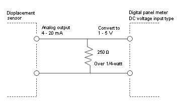
*It is required that the connecting resistance value is within the allowable load resistance of analog output of the Displacement Sensor.
*Be aware that the tolerance of resistance value of 250 Ω indicates an error of output voltage.
What is the service life of Z300 High-precision Laser Profiling System?
The service life of the Z300 depends on the lifetime of the laser.
Therefore it depends on the type of the laser that is being used.
Z300-S5/-S10
Z300-S2
Z300-S60
The following table lists the estimated service life of the above lasers.
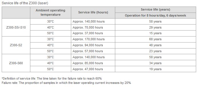
Note:vv10 Sensors were used, and 6 of them fail, the failure rate is said to have reached 60%.
The above data is for reference only. They are not guaranteed values. They will vary depending on the environment in which the Sensor is used.
What problems occur when measuring hot objects with Z300 High-precision Laser Profiling System?
There are three problems. Heat rays generated from the object are confused with the reflected laser beams received by the Sensor, the ambient temperature around the Sensor rises, and the heat creates a layer of air that is at a different temperature, causing light to be refracted and produce errors.
Hot objects emit heat rays. These heat rays can cause measurement errors.
The Z300 Sensors use visible red light lasers. There is a filter on the receiver lens which passes through wavelengths of 600 to 720 nm. The CCD receiver element will not accept wavelengths above 1 μm.
Heat rays emitted from the hot object are similar in wavelength to the laser beam, so the receiver element may detect the heat rays. Conduct tests with the actual system to determine how much it is affected by heat rays.
ZX-L Laser Displacement & Measurement Sensors and Z500 Profile Measuring System face the same problem.
Laser wavelengths of the main Displacement Sensors are as follows: Z300-S2: 650 nm, Z300-S5 and Z300-S10: 670 nm, Z300-S60: 658 nm, Z500-SW2: 650 nm, Z500-SW6 and Z500-17: 658 nm, all models of ZX-L: 650 nm
There may be a heat-related problem. Check the ambient temperature specification in the catalog and install a cooling device (such as a fan) to make sure that the temperature stays within the specified range.
Additional Information: Make sure that cooling is applied regularly to maintain the ambient temperature around the Sensor at a certain level. If the cooling is turned ON and OFF, the Sensor casing and mounting board may expand and contract due to the temperature change, causing measurement errors.
A layer of hot air forms around the hot object, but the air surrounding the Sensor is at room temperature. This forms a temperature gradient between the two locations, which is equivalent to a gradient in air density. Light is refracted where the densities differ. The Z300 uses triangulation, so refraction of light will lead to a measurement error.
If you want to measure a hot object, check first whether these Sensors can be used to make measurements to the required accuracy.
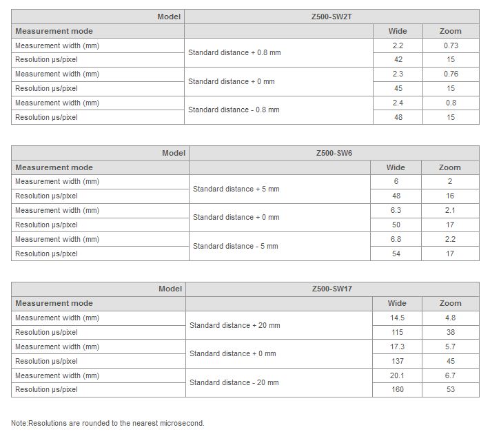
What is the width resolution of the Z500 Ultrasonic Displacement Sensor?
The CCD size of the light receiver element of the Z500 is 126 × 1,024 pixels
The width resolution is 126 pixels. The value of the measurement range of each Sensor Head of the Z500 divided by the width resolution is the resolution per pixel.
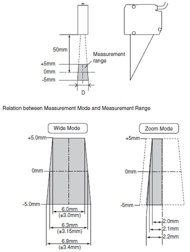
The width resolution is listed below for each Sensor Head when the measurement mode is set to the wide mode.
The measurement range for the standard distance (measurement distance at center) of the Z500-SW2T is 2.3 mm. Therefore, the width resolution is approximately 18 μm/pixel = 2.3 mm/126 pixels.
The measurement range of the Z500-SW6 is 6.3 mm.
Approximately 50 μm⁄pixel = 6.3 mm⁄126 pixels
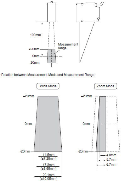
The measurement range of the Z500-SW17 is 17.3 mm.
Approximately 137 μm⁄pixel = 17.3 mm⁄126 pixels
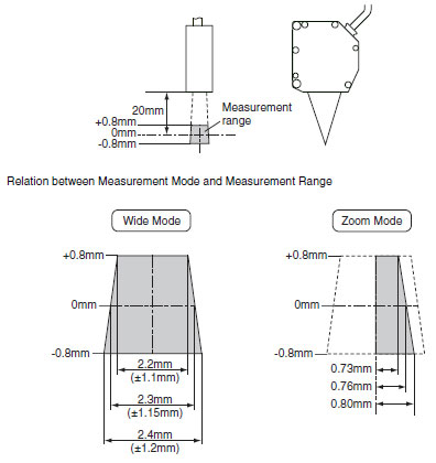
The measurement range varies a little depending on the height of measurement.
The resolution is a calculated value and should be used only as an approximation.
Check the measurement accuracy with the actual system to see if it is adequate for your requirements.
Resolutions are listed for both wide and zoom measurement modes. Please use this information as guide. A diagram showing the measurement range is attached
Does ZX-SF Communications Interface have a baud rate of 9,600 bps?
The model number of ZX-SF11-01 ends with "-01," which indicates that it has a baud rate of 9,600 bps. The standard model (ZX-SF11) has a baud rate of 38,400 bps.
Is the setting for the number of samples to average used for the linear output?
Yes, it is. When the number of samples to average is set, the measurement values are averaged, and the value is displayed on the Amplifier Unit and sent to the linear output.
Averaging is performed using a moving average.
Applicable models: ZX-L-N Smart Sensors, ZX-E Smart Sensors, and ZX-T Series Smart Sensors
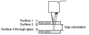
Can Smart Monitor version 1.5 be used to measure the gaps in wafers through glass windows with ZS-LD200 Displacement and Measurement Sensors?
Yes, it can be performed with version 1.5 or higher.
 Automation Systems
  Motion & Power Solutions
  Safety, Vision and IDENT
  Sensing Solutions
  Control Components
  Switching & Accessories
  Switchgear and Trolley Systems
  Process Weighing
  LED Lighting
  Omron
Omron
 Mitsubishi
 Delta
Delta
 Autonics
 Inno
Inno
 Honeywell
 Novotechnik
 Orientalmotor
 Microscan
 IPA
IPA
 Technomech
 Intech
 IOT & Traceability
 Project & Panel Engg.
 Application Case Studies
 Solutions by Industry
 Solutions by Process
 Solutions by Product
 Corporate Information
 Company Profile
 Quality Policy
 Mission Statement
 Chairman's Message
 Intech Group Companies
