Frequently asked questions and answers for General purpose Relays - Industrial Automation
Question
Do you have Relays with overlapping contacts
Answer
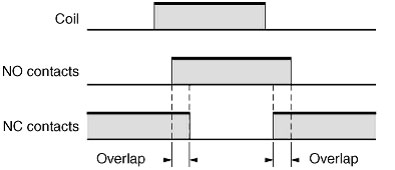
Yes, there is G2A-4L32A General-purpose Relays. OMRON calls "overlapping contacts" "MBB (Make Before Break) contacts". (Specify the coil voltage after the model number.)
MBB Contacts (G2A-4L32A)
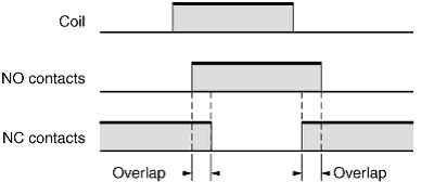
"MBB contacts" is an abbreviation for Make Before Break contacts. Relays with MBB contacts have an overlapping mechanism where the NO contacts close before the NC contacts open. These are also called "continuous contacts."
Question
What is the number of contact poles?
Answer
It is the number of contact circuits, such as two poles or four poles.
Question
The Relay does not operate even when voltage is applied. Why is this?
Answer
The following causes are probable.
1. Disconnected Coil
Ultrasonic cleaning or applying an overvoltage may cause the coil to become disconnected.
2. Insufficient Coil Voltage
Check the voltage being applied to the coil. The Relay will not operate if the voltage is lower than the must-operate voltage.
3. Incorrect Polarity of Applied Voltage
A Relay equipped with a diode that absorbs coil counter-electromotive force will not operate properly if the positive and negative voltages applied to the coil are connected incorrectly.
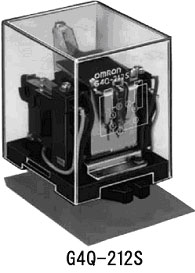
Can MR2P Ratchet Relays be replaced with G4Q-212S Ratchet Relays?
AnswerYes, MR2P is a discontinued product which can be replaced with G4Q-212S. (Specify the coil voltage.) MR2P and G4Q-212S are interchangeable.
Note:These Relays are socket-mounted plug-in type. The Sockets are separately sold.
What is the correct way of ordering Relays?
Example: MK2P AC100/110V General-purpose Relays
You must specify the coil voltage after the OMRON Relays model number. Specify the coil voltage after the model number as shown in the example.
The Relay operates. However, there is no current flowing between the contact points. I want to know why.
The presumed reasons are as follows
(1) Transformation of Relay's internal components due to the shock of falling
The shock with which the Relay unit is dropped by mistake makes the internal components of the Relay transformed and then the connection between contact points unstable. Handle it with due care.
(2) Lifetime limitation due to contact erosion
Switching a load makes the contact points erode. When reaching the end of the working life, even if the Relay operates, the current flow becomes unstable. In this case, change the Relay.
(3) Loose contact points in minimum load switching
If a Relay with silver or silver-alloy contacts is used for minimum load switching, insulating capsules such as sulfureted one are easily produced, and then loose connection may be caused.
For minimum load switching, it is recommended to use a Relay with gold-plated cross-bar twin or twin contacts.
(4) Foreign body stuck between contact points
Especially with exposure types, if dusts, molding powders, wire debris or coating materials are stuck between contact points, it may cause loose connection. In this environment, it is recommended to use a Relay in a case.
(5) Loose contact points in inductive load switching
Carbon is produced by arc discharge generating between contact points in inductive load switching using solenoid or valve. Carbon accumulates on the surface of contact points, and thus the current flow may become unstable depending on an applied load. Surge protection suitable for the applied load is required.
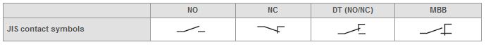
What is the contact form?
The contact configuration is called the contact mechanism.
Types of contacts include NC contacts (break contacts), NO contacts (make contacts), and transfer contacts.
What is the "maximum switching current"?
It's the maximum current that can be switched by the contacts. Relays cannot be used if this value is exceeded.
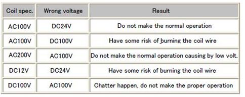
An AC voltage of 200V was applied to a coil with rated voltage of 100VAC. Is there any problem?
Yes. When an AC voltage of 200V is applied to a coil with rated voltage of 100VAC,problems such as coil burnout may occur. As for problems caused by other incorrect voltage applications, refer to the following table.
Be careful not to apply other voltages than the rated voltage.
What is a failure rate?
A failure rate expresses a rough guide to the switchable limits of electronic circuits and other very small loads (i.e., microloads).
The percentage of failures per unit time during continuous relay switching (number of operations) under individually specified test types and loads. The failure rate will change depending on the switching frequency, the environmental conditions, and the expected reliability level. Failure rates must always be checked on equipment under real operating conditions.
The failure rate is listed as the P level (reference value). This expresses the failure level at a reliability level of 60% (λ60) (JIS C5003).
Example:
λ60 = 0.1 × 10⁻⁶/operation means that 1/10,000,000 failures can be expected at a reliability level of 60%.
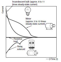
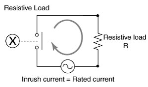
What types of load are there (resistive loads, inductive loads, lamp and capacitor loads)?
The load types and their characteristics are as follows.
Nichrome heaters and other loads to which the same current continues to flow when voltage is applied
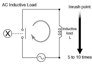
Motors, solenoids, and other loads with inrush current
The load types and their characteristics are as follows.
Loads with inrush current even larger than with inductive loads
AC Loads and Inrush Current:
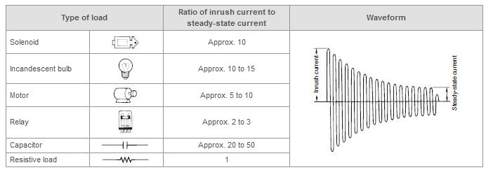
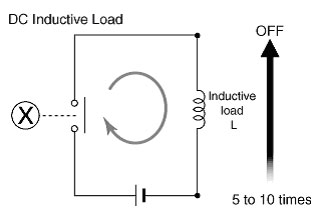
DC Loads and Inrush Current:
A Relay burned out. Why is this?
The following causes are probable.
If overvoltage is applied to the coil, the coil's insulating film will be destroyed, and short-circuiting will cause high temperature. The color of the coil will change, and the resin around the coil will melt. It is also possible that an external surge was applied to the coil circuit, but this is often difficult to determine.
Abnormal heat is generated when there is contact chattering and arcing continues between contacts. If the fluctuation in the voltage applied to the coil is large, the cause may be that the Relay contacts are frequently switched.
If, for example, the connected load exceeds the Relay's contact capacity or switching ability, arc heat will melt the contacts. If this occurs, the DC load conditions will be more stringent than the AC load conditions.
Do you have Relays with MBB (Make Before Break) contacts?
Yes, there is G2A-4L32A General-purpose Relays. (Specify the coil voltage after the model number.)
"MBB contacts" is an abbreviation for Make Before Break contacts. Relays with MBB contacts have an overlapping mechanism where the NO contacts close before the NC contacts open. These are also called "continuous contacs."
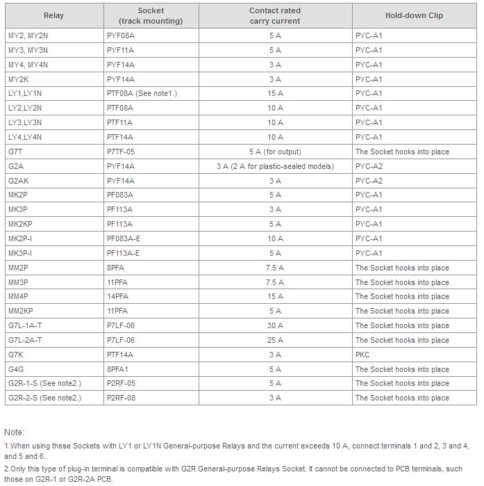
Which Sockets and Hold-down Clips can be used for each Relay?
Common combinations are shown in the following table.
The Relay will not reset. What are the probable causes?
Probable Causes:
There are probable causes on the contact side (output side) and on the coil side (input side).
1. Contact Fusing
Excessive current flows to the contacts, and the resulting heat generated causes the contacts to melt, and then stick together inseparably. This occurs when the contacts circuit short-circuits or when a load to which excessive inrush current flows is switched.
2. Contact Transfer (Shift and Locking)
One contact melts or evaporates and transfers to another contact. Generally, the positive side is concave and the negative side is convex. The concave and convex portions will stick together and become inseparable. This problem depends on usage conditions when switching lamp loads and capacitor loads to which excessive inrush current flows or when using AC loads.
3. Contact Sticking
When Relays with gold-clad contacts, particularly signal Relays, are cleaned with ultrasound, the ultrasonic energy causes the contacts to become attached and immobile as if welded. Relays are available that are resistant to ultrasonic cleaning.
4. Penetration of Adhesive Material
Flux, coating, or other substance penetrates the Relay and forms an adhesive material that sticks to the Relay drive section and makes it mechanically immobile.
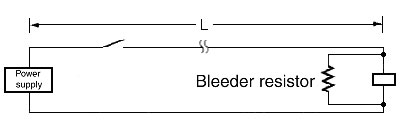
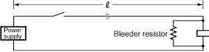
1. Long Wiring Distance with Coil and Power Supply
If the wiring distance (L) from the power supply is long, be sure to measure the voltage on both sides of the Relay coil terminal, and set the power supply voltage so that the rated voltage is applied.
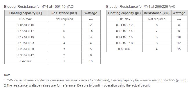
If wiring is performed over a long distance in parallel with power lines, voltage may be generated on both sides of the Relay from the floating capacity of the wires and cause reset failures when the coil input power supply is OFF. If this happens, connect a bleeder resistor to both sides of the coil.
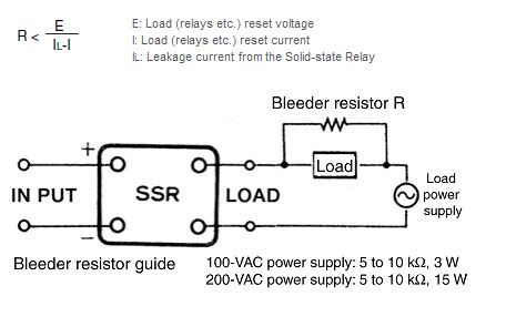
2. Using an Solid-state Relay to Operate a Relay
A few milliamps of leakage current IL flows on the output (load) side even when there is no input signal. Therefore, this leakage current may cause reset failures if it is larger than load reset current. As a leakage current countermeasure, connect a bleeder resistor R in parallel with the load to increase the Solid-state Relay switching current.
What is the "operating time"?
The operating time is the time from when the rated voltage is applied to the coil, until the time when the contacts operate.
With Relays that have multiple pairs of contacts, if there are no other conditions, then the operating time is the time required for the slowest pair of contacts to operate.
The operating time is given for a coil temperature of 23°C or higher. The bounce time is not included.
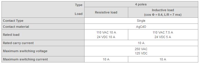
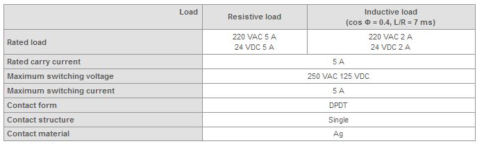
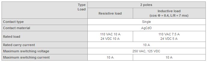
Can 4-pole LY4 General-purpose Relays switch 10 A?
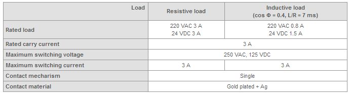
The contact ratings per pole are described below.
For example, for a 110-VAC or 24-VDC Relays are used with a resistive load, the contacts can switch 10 A, but if the load is inductive, a 110-VAC Relays can switch only 7.5 A, and a 24-VDC Relays, only 5 A (not 10 A).
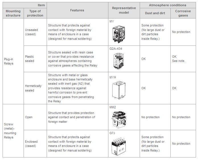
What is the difference between MY4H and MY4 General-purpose Relays?
MYH-series General-purpose Relays are encased in a sealed metal structure containing nitrogen gas. A metal case is used to provide resistance against harmful corrosion to prevent corrosive gases from penetrating the Relays.
Note:
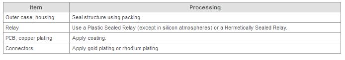
Using Relays in an Atmosphere Containing Corrosive Gas
(Silicon, Sulfuric, or Organic Gas)
Do not use Relays in a location where silicon gas, sulfuric gas (SO2 or H2S), or organic gas is present.
If Relays are stored or used for an extended period of time in an atmosphere of sulfuric gas or organic gas, contact surfaces may become corroded and cause contact instability and obstruction, and terminal soldering characteristics may be degraded.
Also, if Relays are stored or used for an extended period of time in an atmosphere of silicon gas, a silicon film will form on contact surfaces, causing contact failure.
The effects of corrosive gas can be reduced by the processing shown in the following table.
Is there a socket with a terminal cover for G2R General-purpose Relays?
Sockets with finger-protection are available. These Sockets are constructed to make it difficult for a human finger to touch the current-carrying parts. These Sockets have an "-E" at the end of the model number.
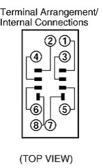
The terminal arrangement printed on the case of MY General-purpose Relays appears to be reverse compared to the terminal numbers indicated on the Sockets. Is this a mistake?
No, the terminal numbers on the Relays and the Sockets are the same.
The terminal arrangement printed on the case of the Relays shows a bottom view of the Relays (the side with the terminals). For this reason the arrangement appears to be in reverse. By placing the Relays in the Sockets, the terminal numbers will match.
Applicable model: MY Series
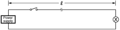
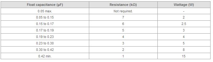
What should I be aware of when operating MY4 General-purpose Relays AC100V Relay from a distance?
The distance depends on the type and installation conditions of the cable. Wiring power supplies over a long distance in parallel with power lines may cause reset failure due to voltage generated at both sides of the Relays from float capacitance in the wires when the coil input power supplies are OFF. If reset failure occurs, connect bleeder resistors to both sides of the coil.
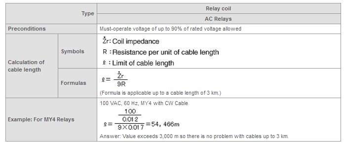
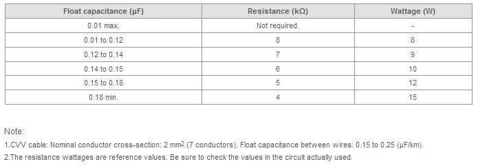
Guideline for Cable Length Limits
Is the rated current of the contacts for MY2 General-purpose Relays 10 A as written on the Relays or 5 A as written in the datasheet?
The rated current is 5 A.
The "10 A 250 VAC" written on the Relays is the UL/CSA rating and not the product specification. International ratings of this kind are based on under conditions specified for each standard. They are not the same as the ratings that satisfy conditions, such as the operating ambient temperature, outlined in the datasheet.
Do not use the Relays with currents exceeding 5 A.
Example: The UL standards specify 6,000 operations as the minimum test condition, whereas MY2 specifies 500,000 operations minimum.
How do you find the maximum switching capacity?
This following graph can be used to find how much current can be applied to the contacts. A description of how to interpret the graph to find out how much current can be applied at what load circuit voltage (contact voltage) is provided below.
The following figure shows how to find the maximum switching capacity for a 200-VAC inductive load.
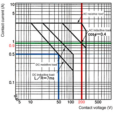
1. Draw a vertical line where the contact voltage is 200 V (red line).
2. Draw a horizontal line from the point of intersection with the AC inductive load curve (green line).
3. Where the green line intersects the contact current axis is the maximum switching capacity. In this case, the switching capacity is 0.9 A.
Example:
To what voltage must the contact voltage be limited in order to switch a 0.5-A DC inductive load?
Answer:
Keep the voltage below 50 VDC (blue line).
What happens when the rated carry current is exceeded at the switching section (contact section)?
The symptoms depend on whether the contacts have power supplied to them only or they are switched as well.
1. Power Supply Only
Generated heat may cause deterioration of the contacts and/or conductor insulation, and reduce the springiness (reset force) of the contact springs.
2. Switching
Contact transfer, welded contacts, OFF faults, abnormal consumption, and increase of contact resistance may occur.
Does a switching capacity double when two contact points in the Relay are connected in parallel?
No, it does not double.
Actually two contact points don't always switch at the same time (a slight switching-timing delay occurs between them), thus all loads are instantaneously applied to only a single contact point.
How long can LY2 AC200V General-purpose Relays withstand a momentary power interruption?
There is no specific time. The time may depend on the power supply phase at which power is interrupted, but generally the contacts may open after about 1 ms.
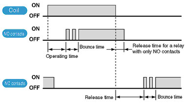
Is the bounce time included in the operating time and the release time?
No, bounce time is not included in operating time and release time.
The operating time is the time from when current is applied to the coil, until the NO contacts (make contacts) turn ON.
The release time is the time from when the coil is turned OFF, until the NO contacts turn OFF. For double-pole contacts, it is the time until the NC contacts close.
Do you have any Relays that can be used with a 12-VDC input and 200-VAC load?
Yes, MY2N DC12 General-purpose Relays has 2 contact poles (contact form: DPDT) and an indicator.
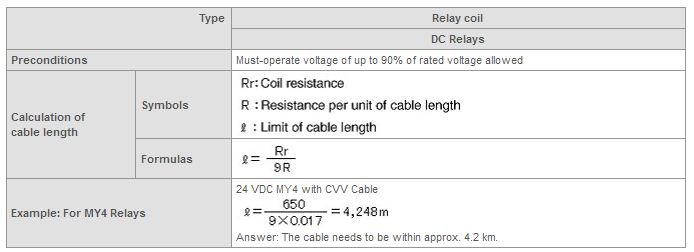
What is the maximum distance for operating MY4 DC24V General-purpose Relays?
The distance depends on the type and installation conditions of the cable. Both ends of the Relays coil must measure at least 90% of the rated coil voltage to operate without problems. It is essential to check this beforehand.
Reference Information: Guide to Limits of Cable Lengths

Why do Relays switching capacity vary with the type of load?
Generally, the switching capacity for an inductive load will be lower than the switching capacity for a resistive load due to the influence of the electromagnetic energy stored in the inductive load.
Example: MY2 General-purpose Relays

When AC inductive loads are used, an inrush current of 5 to 10 times (varies with load) the steady-state current will be generated.
For DC inductive loads, 5 to 10 times (varies with load) the counter electromotive force is generated. Allow for a margin when selecting Relays.
Will the power supply be damaged if the polarity of the coil voltage is connected in reverse for MY2N-D2 General-purpose Relays?
If the polarity is reversed, the built-in diode will short-circuit, damaging not only Relays, but possibly also power supplies.
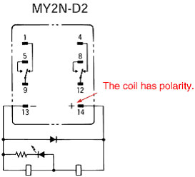
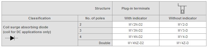
What does the "D2" in MY[]N-D2 General-purpose Relays indicate?
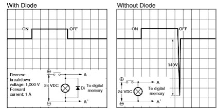
It indicates that the relays have a built-in diode to suppress surges generated from the DC coil of relays.
When transistors are used to operate relays, any effects on the transistor caused by the surge, such as deterioration and breakdown, will be eliminated.
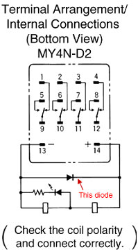
Note:
1.Make sure that the polarity is correct.
2.The reset time will be longer, but it will still be within 20 ms.
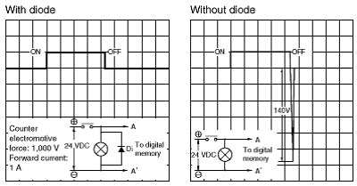
3.Diode characteristics:
Reverse breakdown voltage: 1,000 V
Forward current: 1 A
How long can the MY2 AC100V General-purpose Relays withstand a momentary power interruption?
There is no specific time. The time may depend on the power supply phase at which power is interrupted, but generally the contacts may open after about 1 ms.
Are the Sockets and Relays terminal numbers the same?
Yes, they are the same.
The terminal arrangement/internal connections printed on the case of the Relays shows a bottom view of the Relays. For this reason the arrangement appears to be in reverse.
Applicable model: MY Series General-purpose Relays
Why do some Relays have different maximum contact currents and rated carry currents?
Sometimes even if there is sufficient current-carrying capacity between the contacts and conductors connected to the contacts, the contact switching capacity may be small.
The current that can be supplied continuously to contacts without exceeding the maximum temperature when the contacts are not switching.
The maximum contact current that can be switched. This value must not be exceeded.
What other models can use the same Sockets as the G2R General-purpose Relays?
Refer to the following table.
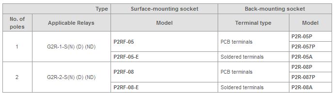
Note:
1.These Sockets have lock mechanisms to hold the Relays in place.
2.Sockets with "-E" at the end of the model number have finger protection. Round crimp terminals cannot be used. Use forked crimp terminals.
We were using G2R General Purpose Relay to turn a solenoid valve ON and OFF, and sparks at the contact damaged the relay after only about 3 months of use. What caused this, and what kind of countermeasure is there for it?
There is no specific time. The time may depend on the power supply phase at which power is interrupted, but generally the contacts may open after about 1 ms. It's possible that a surge resulted from reverse voltage. This speeds up the deterioration of the contacts. Try inserting a surge suppressor in parallel with the load.
Do you have Relays that can hold the contacts?
Yes, there are Latching Relays, such as those in MY2K Series General-purpose Relays.
Latching Relays have a set coil to turn the Relays ON, and a reset coil to turn them OFF.
There are Latching Relays other than those in MY2K Series such as G2AK, MKK, and MMK General-purpose Relays.
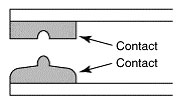
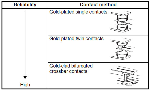
When twin contact points and cross-bar twin contact points are compared to a single contact point, what are the characteristics of the former?
In minimum load applications, contact reliability of twin contact points is higher than that of a single contact point.
Since twin contact points have simply two contact parts, their failure rate related to contact failure is lower than that of a single contact point.
Additionally, cross-bar twin contact points provide further enhanced contact reliability in minimum load applications thanks to their contact form.
However, this theory is not applied for high power load applications, so that a single contact point without AU plating is adopted.
Has MY4N-CR General-purpose Relays become smaller?
The previous MY4N-CR was taller, but a new version was created in October 1999 and the dimensions are the same as a standard MY4.
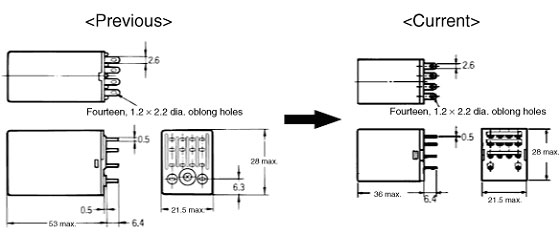
Applicable models: MY2(N)-CR, MY4(N)-CR, and MY4Z(N)-CR (excluding models with special coil voltage specifications).
How do you use the durability curve?
The durability curve is used to check the maximum switching capacity (expected service life). The following example will be used to describe how to find the maximum switching capacity of a contact at a particular contact current.
Look at the graph to determine what is the expected service life of Relays with 1-A contact current and 20-VDC resistive load.
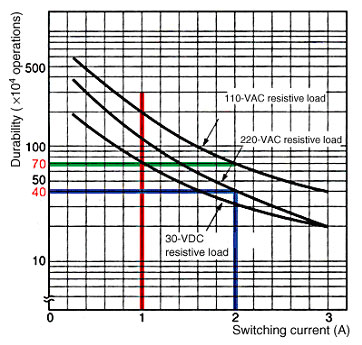
1. Draw a vertical line where the switching current is 1 A (red line). 2. Draw a horizontal line from the point of intersection with the 30-VDC resistive load curve (green line). 3. Where the green line intersects with the durability axis is the expected service life. In this case, the expected number of operations is 700,000 operations.
Example
:
What is the expected service life for a 220-VAC 2-A resistive load?
Answer:
Approximately 400,000 operations (blue line).
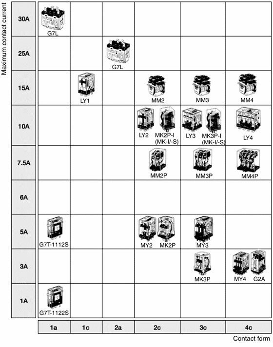
How do you choose General-purpose Relays and Power Relays?
The table below contains General-purpose and Power Relays for control panels. It does not include Relays for PCBs or Terminal Relays.
Check the necessary number of contacts, the contact form, and the maximum contact current (given for a resistive load) in this table.
Can the PTF08A-E Socket be used with LY1 or LY2 General-purpose Relays?
Yes, it can be used. When there is an "-E" at the end of the model number, it indicates that Relays have finger protection (i.e., a terminal cover). (Round crimp terminals cannot be used. Use forked crimp terminals.)
Note:When using PTF08A-E, PTF08A, or PT08 with a LY1, connect between sockets terminals 1 and 2, 3 and 4, and 5 and 6 when using over 10 A.
What happens when the maximum allowable coil voltage is exceeded?
When voltage is applied to the coil, the coil resistance produces heat. When current is applied continuously, the temperature rises and the maximum allowable voltage is determined. If this voltage is exceeded, the coil may burn.
The maximum allowable voltage is the maximum voltage that can be applied to Relays coil; it is not the continuous allowable value.
What is the value in parentheses for models with the coil voltage listed as "100/(110) VAC"?
"100/(110) VAC" indicates that the coil has 3 ratings.
3 ratings
100 VAC at 50 Hz
100 VAC at 60 Hz
110 VAC at 60 Hz
If the specification has "100/110 VAC," the coil has 4 ratings, i.e., it also has "110 VAC at 50 Hz" in addition to the above. The MY and LY General-purpose Relays are examples of Relays with 4 ratings.
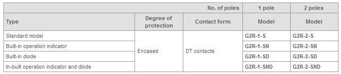
Can G2R-[]-SN General-purpose Relays be replaced with a G2R-[]-SND?
Yes, it can.
G2R-[]-SND has an in-built diode that absorbs the counter electromotive force (surge) generated by the coil. The same Sockets can be used.
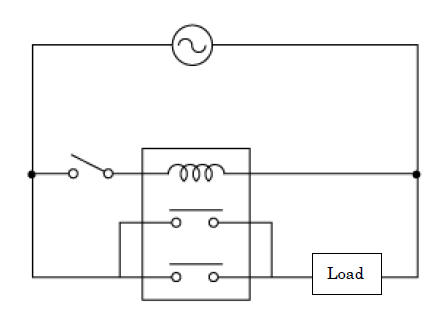
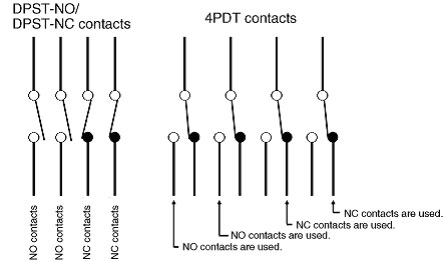
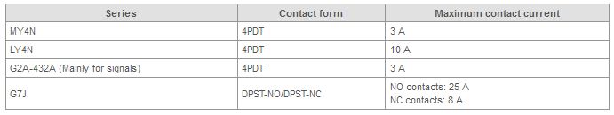
Can 4PDT Relays be used as DPST-NO/DPST-NC Relays?
Yes, 4PDT Relays can be used as DPST-NO/DPST-NC Relays.
Refer to the following figure and table.
Are there restrictions on the direction that the MY General-purpose Relays can be mounted?
There are no restrictions. However, it is best to mount MY so that vibration and shock will not be applied in the direction of movement of the contacts.
Applicable models: MY Series
What is the difference between LY2N and LY2 General-purpose Relays?
LY2N have LED indicators that turn ON when voltage is applied to the coil.
Can MY4 AC100/110V General-purpose Relays and MY4 AC110/120V both be used with a 110-VAC coil voltage?
Yes, they can both be used because 100/110-VAC MY Series have the following four ratings.
100 VAC at 50 Hz
100 VAC at 60 Hz
110 VAC at 50 Hz
110 VAC at 60 Hz
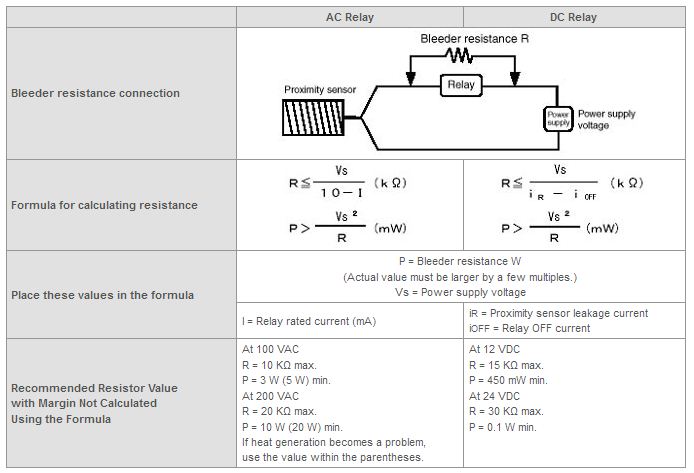
What bleeder resistance is required when operating the AC coil of MY General-purpose Relays from a distance?
Refer to the following table.
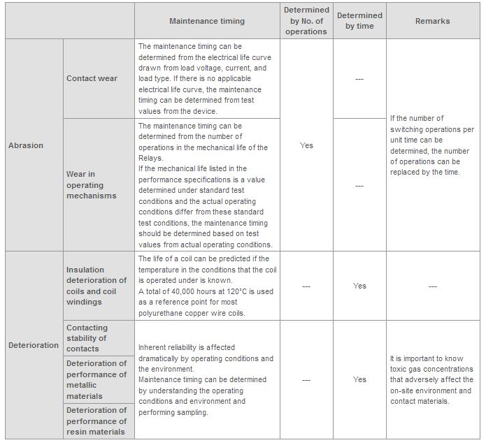
What are the measures used to judge the General Purpose Relays' lifetime?
Welding, contact failure, insulation degradation and so on are cited as the measures used to judge the General Relay's lifetime.
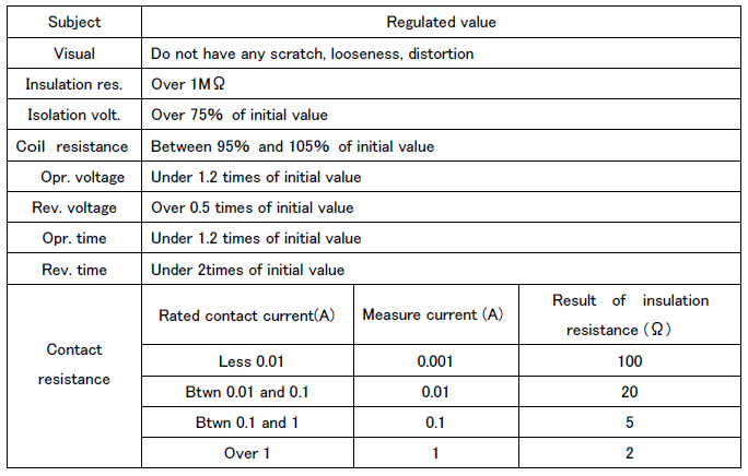
What is the approach to perform maintenance for Relays?
There are two main types of maintenance: corrective maintenance (i.e., inspections and replacements that are performed after a failure has occurred) and preventative maintenance (i.e., inspections and maintenance that are performed before a failure occurs).
Some of the important issues with preventative maintenance is when to perform inspections and replacements, how to know when that is required, and how to determine the timing.
The factors that must be considered when determining maintenance schedules for Relays is the level of importance of the target device, and the required reliability level, when looking at maintenance from the device or system perspective. There are also different types of failure for the different characteristics and items based on the type of Relays.
Relays failure types can be broadly classified into failures from wear, typified by worn out contacts, and deterioration failures, such as layer shorts in coil windings.
In general, once the conditions of use for the Relays have been determined, it is possible to predict maintenance requirements because types of wear, such as contact wear, and the timing of wear related failures are related to the number of operations. On the other hand, deterioration failures, such as layer shorts in coil windings, are greatly affected by the inherent reliability of the Relays being used. The maintenance requirements are affected by use reliability, e.g., operating conditions and on-site environment.
This means that the failures are often different for each case, which makes it difficult to determine a maintenance schedule in advance.
In actual operation, wear and deterioration progress at the same time and it is important to know which type of failure is going to occur first when determining maintenance schedules.
The following items are useful for reference when determining maintenance timing.
Can the same Sockets be used when MY2 General-purpose Relays is replaced with MY2N-D2?
Yes, the same Sockets can be used.
MY2N-D2 has coil polarity, so take care when wiring.
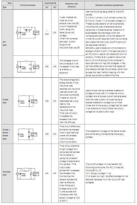
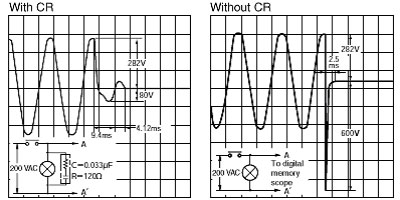
Choosing from among CR elements, diodes, varistors, and other kinds of surge suppressor elements, which is the most effective for protecting contacts?
For a DC load, a diode is generally the most effective, and the next most effective is CR elements. For an AC load, a varistor or CR elements are the most effective.
What is the life span of the coils when voltage is continuously applied to coils for MY2 AC100V General-purpose Relays?
The general heat-resisting life span for the wire is 40,000 hours. Therefore, if polyurethane copper wire is used in the coil, the life of the coil is approximately 5 years. (A life of 5 years is applicable when applying the rated voltage in a normal environment.)
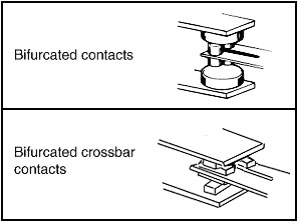
What is the difference between MY4Z General-purpose Relays and MY4Z-CBG?
Both relays are for switching microloads, but they have different contact mechanisms.
MY4Z have bifurcated contacts, whereas MY4Z-CBG have bifurcated crossbar contacts. CBG models are more reliable for high-frequency microload switching.
Be careful because they have different contact ratings.
What happens if the maximum contact voltage is exceeded?
If the maximum contact voltage is exceeded, the duration of continual arcing during load switching will be exceeded and the load will not be able to be disconnected.
How can we consider the contact resistance in the minimum load area?
When switching a minimum load, contact resistance of the contact points may be considered a problem.
However, even if a high contact resistance happens to be generated, it may recover in the subsequent operation. Also, formation of contact films may increase the contact resistance.
Whether or not a contact resistance value is considered a problem should be judged by the type of problem occurred in the used circuit.
For this reason, a criterion for failure of Relay contact resistance is defined with an initial value. The minimum applicable load is one of the measures of failure and the failure rate is usually expressed as P-level (reference value).
In addition, some of Relay contacts are suitable for minimum load switching and some are not.
The clear relay case has turned black. Is there a problem?
Carbon and contact dust generated by the organic gas that results from arc discharge during load switching accumulates on the inside of the case. The discoloration is not a problem.
If using an inductive load, a surge suppressor can be introduced as a countermeasure against discoloration caused by arc discharge.
Can any of MY2 General-purpose Relays switch 10 A at 100 VAC?
The maximum contact current for MY2 Series is 5 A. Consider using an LY2 Series General-purpose Relays for operation at 10 A.
LY2 Series have the following contact ratings. Switching at 10 A is possible with 110-VAC or 24-VDC resistive loads. If using an inductive load, 7.5 A at 110 VAC or 5 A at 24 VDC can be used.
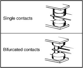
What Bifurcated-contact Relays are suitable for switching microloads?
The highly reliable Bifurcated Crossbar Contact Relays or Bifurcated Contact Relays are recommended for switching microloads.
Bifurcated crossbar contacts: G2A Series Power Relays, MY4Z-CBG Series General-purpose Relays
Bifurcated contacts: MY4Z Series, MK[]ZP Series General-purpose Relays
What is the operating voltage of MY2 AC200/220V General-purpose Relays?
The rated coil voltage is less than 80% of the operating voltage.
Therefore MY2 AC200/220V operates at 200 VAC x 80% = 160 VAC max. (when coil temperature is 23°C).
Can a direct current be applied to one set of contacts and an alternating current to another set of contacts on the same Relay?
Yes, but problems may occur depending on the load conditions. If different currents are applied to the Relay, do not have it simultaneously switch a large load and a microload, and do not use the Relay in a circuit with a difference in electric potential across the circuit.
The purity of the contacts used for microload switching will be lost due to the contact spattering that occurs when switching a large load, and this may cause contact failure when switching a microload.
Could the Relays become detached from the Sockets if I don't have Hold-down Clips to prevent them from becoming loose?
Yes, the Relays may become detached if the equipments are exposed to vibration or shock.
What is the difference between LY[]N General-purpose Relays and LY[]N-D2?
This is the standard model with an indicator.
This is the model with in-built diode that suppresses the counter electromotive force generated from the DC coil of Relays. When operating Relays with transistors, the diode eliminates problems such as deterioration and breakdown of the transistor caused by counter electromotive force.
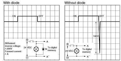
What should I be aware of when operating MY2 General-purpose Relays with a transistor?
When Relays turn OFF, counter electromotive force (surge) is generated. Counter electromotive force causes transistors to deteriorate or breakdown. Use Relays with a built-in diode for surge suppression.
Note:
1.Make sure that the polarity is correct.
2.The reset time will be longer but it will still be within 20 ms.
3.Diode characteristics:
Withstand inverse voltage: 1,000 V
Forward current: 1 A
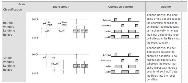
What's a latching relay?
It is a relay that is set (ON) or reset (OFF) by the input of a pulse voltage. Even after the input voltage is interrupted, this relay maintains its set or reset condition until it receives the next inverting input. It is also called a keep relay.
a magnetic holding type and a mechanical holding type.
a single-winding type and a double-winding type.
What is the difference between MY4Z General-purpose Relays and MY4?
They have different contact mechanisms.
MY4 has single contacts, whereas MY4Z has bifurcated contacts, as indicated by the "Z" at the end of the model number. Bifurcated contacts are suitable for operating microloads. MY4Z has a shorter electrical life.
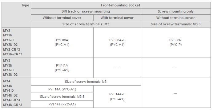
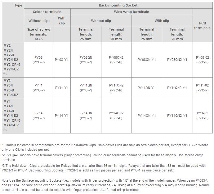
Which Sockets and Hold-down Clips are for MY General-purpose Relays?
Refer to the following table.
Do you have any Relays with gold-plated contacts?
Yes, Relays from MY4ZN-CBG General-purpose Relays, G2A, MY4Z, MY[]Q, and MY4N Series have gold-plated contacts.
Even if Relays are not used and just stored, the contacts may deteriorate. Contacts are less susceptible to the environment if gold plated.
Consider different contact mechanisms when using microloads.
When LY2N General-purpose Relays are OFF, the indicator is lit slightly. What is the problem and countermeasure for this?
This problem may be the result of residual voltage caused by float capacitance in the wires or leakage current when Relays is OFF. This may also cause reset failure.
Check with the cable manufacturer for how much float capacitance the cables retain. Also check the amount of leakage current with connected sensor.
If needed, connect a bleeder resistor in parallel with Relays coil.
Example: Countermeasure against Leakage Current when Using Proximity Sensors and Relays
Connect the bleeder resistor and so that the leakage current that normally flows through the load (Relays coil) is by-passed.
What is the maximum allowable coil voltage of the MY2 AC100/110V General-purpose Relays?
The maximum allowable voltage is 110% of the coil rating. In this case, it is 121 VAC (110 VAC x 110% = 121 V).
Applicable model: MY Series
Do you have any Relays that can switch more than 3 A?
Yes, MY General-purpose Relays, LY, and MK Series.
Can the gap on the case be taped to prevent dust from entering Relays?
It is not recommended to put tape on the case because it may lower the ability to dissipate heat. Use MYQ Plastic Sealed Relays or Solid-state Relays.
What are the recommended replacement products for G2J General-purpose Relays or G4J?
1. Replacement products for G2J and G4J depend on the model number. Check in the following table.
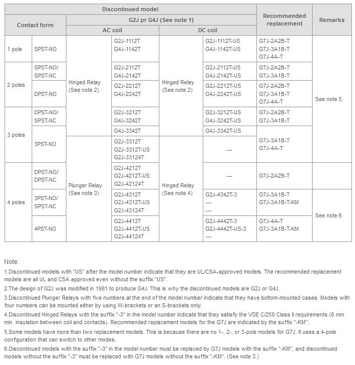
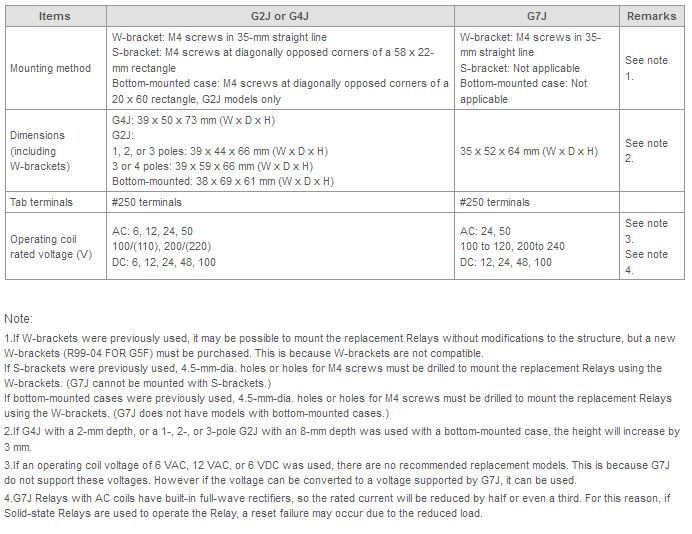
2. Comparison of the G2J or G4J, and G7J
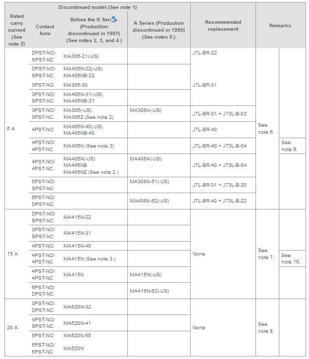
What are the recommended replacement products for MA Contactors?
1. Replacement products for MA depend on the model number. Check in the following table.
Note:
1.Discontinued models with "US" after the model number indicate that they are UL/CSA-approved models. The recommended replacement J7L-BR Auxiliary Relays are all UL and CSA approved even without the suffix "US".
2.Discontinued models with the suffix "Z" to the model number are bifurcated contact models with a 4-A rated carry current.
3.Only these discontinued models had DC coils. Other models only have AC coils. The DC coils came in 6, 12, 24, 48, 100, or 200 VDC, and the SPST-NC contacts are internally connected.
4.Discontinued model MA406N with the suffix "B" in the model number are models with diagonal mounting holes at various pitches.
5.The discontinued A-series Relays were able to be snapped onto DIN Track.
6.When the rated carry current is 6 A, the recommended replacement model is J7L-BR, or with J73L-B Surface-mounting Auxiliary Contact Units.
7.When the rated carry current is 15 A, there are no recommended replacement products. This is because none of the replacement models have contacts that can switch 15 A.
If the only reason that Relays require 15 A is to switch 3PST-NO contacts, the 3PST-NO contacts can be constructed using J7L-09-11 Contactors, and the remaining contacts can be built into the J7L-09-11. These can be mounted on a J73L-B, and be used as the replacement product.
8.When the rated carry current is 20 A, there are no recommended replacement products. This is because none of the replacement models have contacts that can switch 20 A.
If the only reason that Relays require 20 A is to switch 3PST-NO contacts, the 3PST-NO contacts can be constructed using J7L-18-11 Contactors, and the remaining contacts can be built into J7L-18-11. These can be mounted on J73L-B, and be used as the replacement product.
9.The recommended replacement model J7L-BR-40 has only 24-VDC DC-coil models. For other voltages, there are no recommended replacements.
10.The recommended replacement model J7L-09-11 has only 24-VDC DC-coil models. For other voltages, there are no recommended replacements.
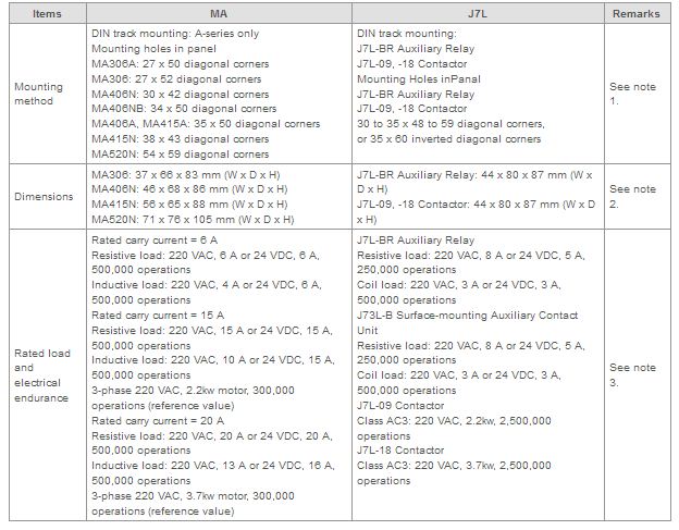
2. Comparison of the MA and J7L
Note:
1.New mounting holes must be made if screw-mounting Relays on a panel.
2.The replacement model is larger in depth. If using J73L-B, the height will increase by 30 mm, making it a total height of 117 mm.
3.If a model with a rated carry current of 6 A is replaced with J7L-BR or J73L-B, the electrical durability will decrease.
Do you have any General-purpose Relays with a rated coil voltage of 380 or 400 VAC?
Relays can be used for a rated coil voltage of up to 200 VAC, and Contactors can be used for up to 400 VAC. There are no Relays with a rated coil voltage of over 240 VAC.
To operate at 400 VAC, use a transformer to reduce the voltage or use Contactors.
Is there any data on the Mean Time Between Failures (MTBF) of relays?
There is no data for the Mean Time Between Failures (MTBF) for Relays. This is because the mean failure rate greatly depends on the current flowing through the contacts, the load type, switching frequency, ambient temperature, and whether Relays are connected to an AC or DC load.
The failure rate P reference value and endurance curves can be used as indicators for the frequency of relay failures and service life.
What is coil surge?
It is a characteristic of the coil in which a large reverse voltage is momentarily generated when Relays are turned OFF. To deal with this problem, some Relays are equipped with surge-absorbing circuits.
When contacts are used for input, surge-absorbing circuits can be used to extend the service life of Relays, prevent the effects of noise, and minimize the production of carbides and nitric acid caused by arcing.
When semi-conductors, such as transistors, are used for input, reverse voltage is generated and may cause Relays to breakdown.
In most cases it is good to install a surge-absorbing circuit.
 Automation Systems
  Motion & Power Solutions
  Safety, Vision and IDENT
  Sensing Solutions
  Control Components
  Switching & Accessories
  Switchgear and Trolley Systems
  Process Weighing
  LED Lighting
  Omron
Omron
 Mitsubishi
 Delta
Delta
 Autonics
 Inno
Inno
 Honeywell
 Novotechnik
 Orientalmotor
 Microscan
 IPA
IPA
 Technomech
 Intech
 IOT & Traceability
 Project & Panel Engg.
 Application Case Studies
 Solutions by Industry
 Solutions by Process
 Solutions by Product
 Corporate Information
 Company Profile
 Quality Policy
 Mission Statement
 Chairman's Message
 Intech Group Companies
