Frequently asked questions and answers for Temperature Controllers - Industrial Automation
When can the manual reset be used for E5[]N/E5[]K Temperature Controllers?
The manual reset can be used for P or PD control. There is an offset for the set point when using P or PD control because there is no integral control action.
There is no offset if auto-tuning (AT) or self-tuning (ST) is used. The manual reset can be used to set the close to zero. If the control output is high when the PV equals the SV, lower the control output for the manual rese
Set the parameter in Level 1 Mode for the E5[]K, and in Adjustment Level for the E5[]N.
Applicable models: E5AK, E5EK, E5CK, E5AN, E5EN, E5CN, and E5GN
How can ON/OFF control be used to maintain the temperature at 30 degree C?
Change the forward/reverse operation setting to forward operation. When the set point is set (i.e., 30°C), the output will be turned ON when the temperature rises above the set point, and OFF when it falls below the set point.
The output will turn ON when the temperature rises above the set point again. (The point at which the output turns ON depends on the hysteresis.)
Applicable models: All models
What is "Hysteresis"?
ON/OFF control action turns the output ON or OFF based on the set point. The output frequently changes according to minute temperature changes as a result, and this shortens the life of the output relay or unfavorably affects some devices connected to the Temperature Controller. To prevent this from happening, a temperature band called hysteresis is created between the ON and OFF operations.
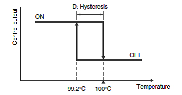
Example:
If a Temperature Controller with a temperature range of 0 to 400°C has a 0.2% hysteresis, D will be 0.8°C. If the set point is 100°C, the output will turn OFF at a process value of 100°C and will turn ON at a process value of 99.2°C.
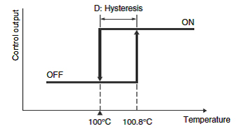
Example:
If a Temperature Controller with a temperature range of 0 to 400°C has a 0.2% hysteresis, D will be 0.8°C. If the set point is 100°C, the output will turn OFF at a process value of 100°C and will turn ON at a process value of 100.8°C.
Setting a large hysteresis will cause the temperature at which the output changes from OFF to ON to be lower than the set point by the amount set for the hysteresis, causing users to sometimes think the output is not working according to the settings. (For Reverse Operation)
On the other hand, if the hysteresis is set to a small value, the output can chatter. The hysteresis thus need to be set to a suitable value.
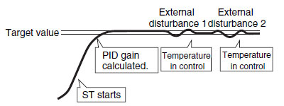
What is "Self-tuning (ST)"?
PID constants must be set according to the characteristics of the controlled system in order to perform suitable temperature control. With previous Controllers, the auto-tuning (AT) function was supported to calculate the PID constants
This meant that starting auto-tuning had to be specified for the Controller and disturbances in the temperature had to be created, such as occur in the limit cycle method.
With self-tuning, the Controller itself determines the start of tuning and tuning is possible without disturbances in the temperature being controlled.
In other words, PID constants are adjusted to the characteristics of the controlled system to continuously enable optimum control.
There are three modes that are used for self-tuning.
(1) Performing tuning and calculating PID constants when set values are changed.
(2) Correcting PID constants when there is external disturbances in the temperature so that the temperature falls within a specified range.
(3) Correcting PID constants when hunting occurs to eliminate hunting.
*The N Series supports only mode 1.
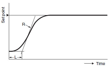
The step response method, a typical calculation method for self-tuning, is described below.
The set value is set to the most commonly used value.
A manipulated variable of 100% is output in stepwise fashion and the maximum temperature ramp (R) and the lost time (L) are calculated and used to calculate the PID constants.
Reference Information: Differences between Auto-tuning and Self-tuning
Auto-tuning (AT)
(1) Auto-tuning is executed only when specified.
(2) A limit cycle signal is output to disturb the temperature in order to perform tuning.
Features:
(1) The Controller determines when self-tuning is to be performed.
(2) A signal is not output to disturb the temperature.
We need to perform heating control. With ON/OFF control, we need to increase the temperature of a 30°C oven to 100 °C. What settings are necessary?
Set direct/reverse operation to reverse operation.
(The factory default is for reverse operation.)
When you set the temperature (e.g., to 100 °C), the control output will turn ON when the temperature is below the set temperature and will turn OFF when it's above the set temperature.
If the temperature falls below the set temperature again, the output will turn ON again.
The point which the output turns ON is also affected by the hysteresis setting.
Please tell me of any precautions for extending the lead wires of a Temperature Sensor.
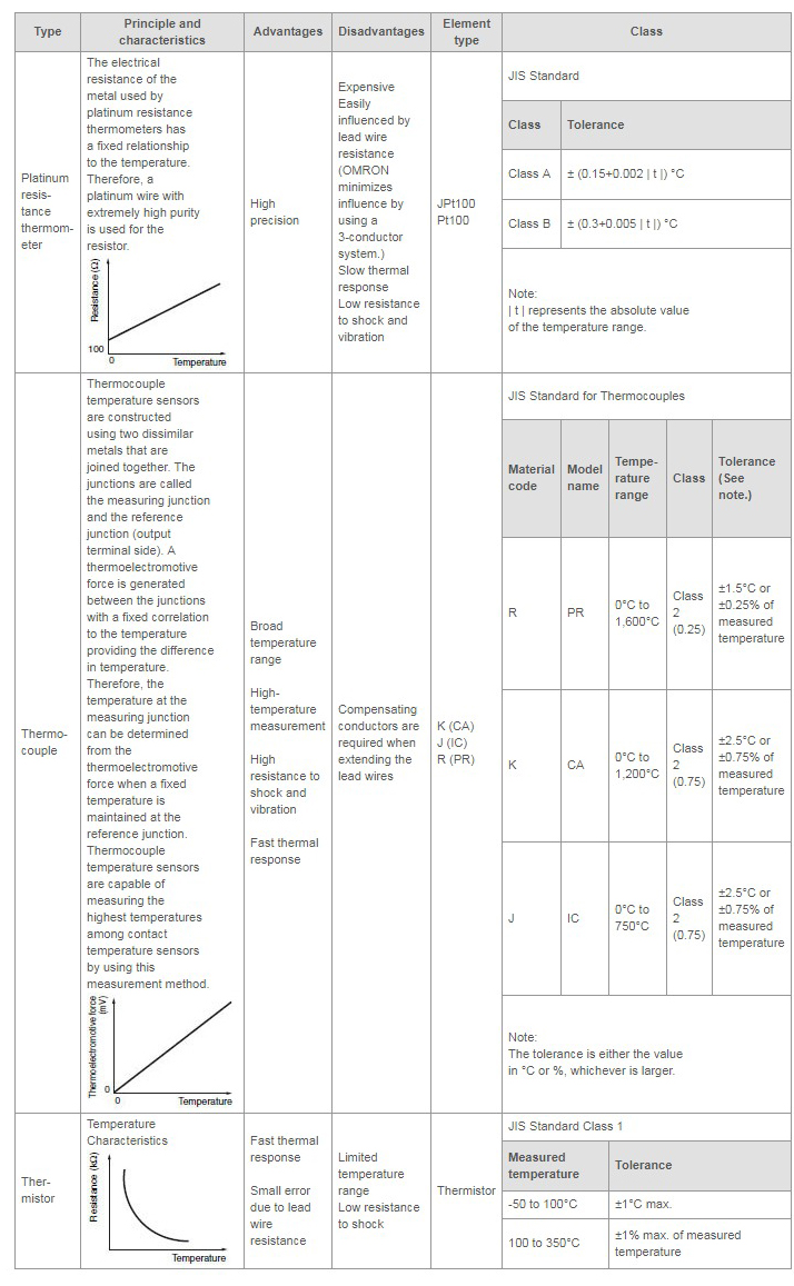
Platinum-resistance Thermometers
All three lead wires used for extension must have the same resistance and the same length. The extension will cause the resistance of the lead wires to affect the display temperature, so use lead wires with thick conductors. (OMRON does not carry lead wires for extension. Use commercially available lead wires.)
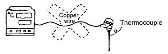
Thermocouples
Be sure to use compensating conductors for the extension. Also, select compensating conductors that suit the characteristics of the Thermocouple. Do not extend the lead wires with compensating conductors that do not suit the characteristics of the Thermocouple, or with ordinary lead wires, as this would prevent proper temperature measurement. Be sure also to connect the wires using the correct polarity (+/-).
Thermistors
Use lead wires with thick conductors for extension. There is no polarity.
General Precautions
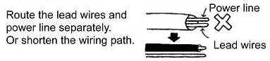
Be careful of the cable routing because extending the lead wires makes the Sensor more susceptible to the effects of electrical noise.
Applicable Models: All models
How do I change the displayed temperature if the displayed temperature is different from the actual temperature on the E5CS?
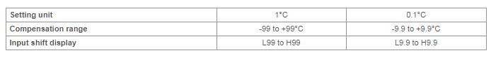
Use the input shift. The setting method is given below.
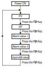
Use the control mode switches to change the control mode. (All switches are OFF for the default settings.)
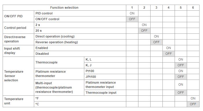
Note:The previous name Pt100 has been changed to JPt100 in accordance with revisions to JIS. The previous name J-DIN has been changed to L in accordance with revisions to DIN standards.
Turn ON switch 4, and after turning ON the power, press the Mode Key until H0 (indicates input shift of 0) is displayed. Press the Up and Down Keys to set the shift value.
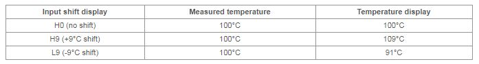
Note:When control mode switch 4 is turned OFF (no input shift display), the input shift is not displayed but the shift value is enabled. To disable input shift, set the input shift value to h0. The shift range depends on the setting unit.
There seems to be a large error in the temperature of the Temperature Controller. Why is this?
The following causes are possible. Please check them.
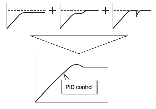
What is "PID Control"?
PID control is a combination of proportional, integral, and derivative control actions. The temperature is controlled smoothly here by proportional control action without hunting, automatic offset adjustment is made by integral control action, and quick response to an external disturbance is made possible by derivative control action.
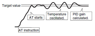
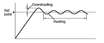
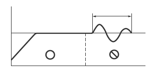
What is "Hunting" and "Overshooting"?
ON/OFF control action often involves the waveform shown in the following diagram. A temperature rise that exceeds the set point after temperature control starts is called overshooting. Temperature oscillation near the set point is called hunting. Improved temperature control is to be expected if the degree of overshooting and hunting are low.
Can Temperature Controllers with a heater burnout alarm detect heater burnouts when using thyristor control?
No, it cannot.
When thyristor control (phase control) is used, the control output is a current output. Therefore the heater burnout alarm of the Temperature Controllers cannot be used.
See whether any of the following methods can be used.
Applicable models:
Applicable models: K8AC-H1[]P[]-FLK Digital Heater Element Burnout Detectors
What's the difference between a Pt100 and JPt100 resistance thermometer?
In January 1, 1989, the JIS standard for platinum resistance thermometers (Pt100) was revised to incorporate the IEC (International Electrotechnical Commission) standard. The new JIS standard was established on April 1, 1989. Platinum resistance thermometers prior to the JIS standard revision are distinguished as JPt100. Therefore, make sure that the correct platinum resistance thermometer is being used.
The following table shows the differences in appearance of the Pt100 and JPt100.
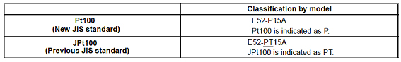
Note: OMRON discontinued production of JPt100 Sensors in March of 2003.
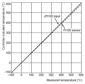
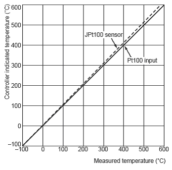
Indicated Temperature when Connecting Pt100 Sensor to JPt100 Input
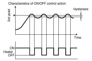
What is ON/OFF Operation?
ON/OFF operation is shown in the following illustration.
The output turns ON to provide current to the heater when the present temperature is lower than the set point.
The output turns OFF to shut OFF the heater when the present value is above the set point. Thus, ON and OFF are repeated near the set point to maintain a constant temperature. This contort method is called ON/OFF operation.
Because the manipulated variable is either 0% or 100% with the set point serving as the boundary, it is also called 2-position operation.
What is the Controller's "direct/reverse operation" and how is it set on the E5[]N?
(1) Direct operation performs control so that the manipulated variable is increased when the process value increases. Reverse operation performs control so that the manipulated variable is increased when the process value decreases.
(2) Set direct operation for cooling control (e.g., control so that the output is turned ON when the temperature is higher than the set point, such as for a refrigerator). Set reverse control for heating control (e.g., control so that the output is turned ON when the temperature is lower than the set point, such as for an oven).
(3) The factory default setting is for reverse control.
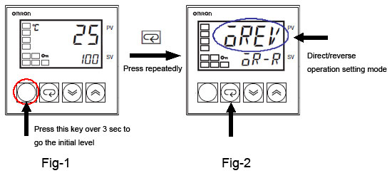
(1) Press the Level Key for at least three seconds from the Operation Level display that appears after the power supply is turned ON. The Initial Setting Level will be entered. (Fig-1)
The Initial Setting Level cannot be entered if the Initial/Communications Protection in the Protect Level (icpt) is set to 2. If necessary, clear protection before starting this procedure
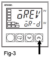
"oreV" will be displayed on the top display (i.e., the PV display) and or-r or or-d will be displayed on the bottom display (i.e., the SV display).
Reverse operation will be used if or-r is displayed on the bottom display and direct operation will be used if or-d is displayed on the bottom display. (Fig-2)
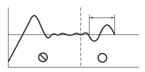
(2) Switching between Direct and Reverse Operation
Switching between direct and reverse operation is performed with the Up and Down Keys. (Fig-3)
Note: If the power to the Controller is turned OFF immediately after changing a setting, the new setting will not be saved. After changing a setting with the Up or Down Key, wait for at least two seconds or press the Mode Key to confirm the setting.
(3) Press the Level Key for at least one second to return to Operation Level.
What is "Two PID Control"?
Conventional PID control uses a single control block to control the responses of the Temperature Controller to a target value and to external disturbances. Therefore, the response to the target value will oscillate due to overshooting if importance is placed on responding to external disturbances with the P and I parameters set to small values and the D parameter set to a large value in the control block. On the other hand, the Temperature Controller will not be able to respond to external disturbances quickly if importance is placed on responding to the target value (i.e., the P and I parameters are set to large values). This makes it impossible to satisfy both the types of response in this case. Two PID control eliminates this drawback while maintaining the strengths of PID control. This makes it possible to improve both types of responses.
Response to the target value will be slow if response to the external disturbance is improved.
Response to the external disturbance will be slow if response to the target value is improved.
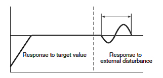
Controls both the target value and the external disturbance response.
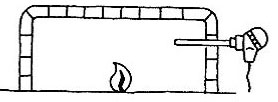
What is "Thermocouple"?
Thermocouple temperature sensors are constructed using two dissimilar metals that are joined together. The junctions are called the measuring junction and the reference junction (output terminal side). A thermoelectromotive force is generated between the junctions with a fixed correlation to the temperature providing the difference in temperature.
Therefore, the temperature at the measuring junction can be determined from the thermoelectromotive force when a fixed temperature is maintained at the reference junction.
Thermocouple temperature sensors are capable of measuring the highest temperatures among contact temperature sensors by using this measurement method.
What is P Action?
With the P action, the control action produces an output of a size that is proportional to the input.
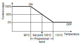
A proportional band is set for the set point. Controlling the manipulated variable (control output size) proportional to the deviation within the proportional band is call the proportional action.
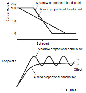
Generally speaking, if the present temperature is lower than the proportional band, the manipulated variable is 100% and then it decreases in proportion to the deviation when the present temperature enters the proportional band. When the set point and present temperature are the same (i.e., then there is no deviation), the manipulated variable is 50%.
This enables smoother control with less hunting than ON/OFF operation.
Example:
If a Controller with a temperature range of 0 to 400 °C is used with a 5% proportional band, the width of the proportional band will be 20 °C.
If the set point is 100 °C in this case, the output will remain ON until 90 °C is reached. When 90 °C is exceeded, the amount of time the output is OFF will increase until it is OFF for the same time it is ON (50%) at 100 °C.
What is P Action?
With the P action, the control action produces an output of a size that is proportional to the input.
A proportional band is set for the set point. Controlling the manipulated variable (control output size) proportional to the deviation within the proportional band is call the proportional action.
Generally speaking, if the present temperature is lower than the proportional band, the manipulated variable is 100% and then it decreases in proportion to the deviation when the present temperature enters the proportional band. When the set point and present temperature are the same (i.e., then there is no deviation), the manipulated variable is 50%.
This enables smoother control with less hunting than ON/OFF operation.
Example:
If a Controller with a temperature range of 0 to 400 °C is used with a 5% proportional band, the width of the proportional band will be 20 °C.
If the set point is 100 °C in this case, the output will remain ON until 90 °C is reached. When 90 °C is exceeded, the amount of time the output is OFF will increase until it is OFF for the same time it is ON (50%) at 100 °C.
Can current outputs (4 to 20 mA DC) be used for the heating and cooling outputs of E5[]K Digital Controllers?
Current outputs can be used by adding E53-C3 Current output Units to control outputs 1 and 2 of E5AK or E5EK. None of E5CK models have current outputs for control outputs 1 or 2.
Applicable models: E5AK, E5EK, and E5CK
We need to start a fan when the temperature rises and stop it when the temperature drops.
Set cooling control (direct operation).
Change the direct/reverse operation setting to direct operation.
For example, if you set the temperature (e.g., to 30 °C), the control output will turn ON when the temperature is above the set temperature and will turn OFF when it's below the set temperature.
If the temperature rises above the set temperature again, the output will turn ON again.
The point at which the output turns ON is also affected by the hysteresis setting.
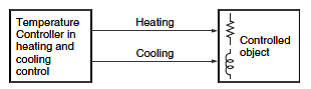
What is "Heating and Cooling Control"?
Temperature control over a controlled object would be difficult if heating was the only type of control available, so cooling control was also added. Two control outputs (one for heating and one for cooling) can be provided by one Temperature Controller.
Set cooling control (direct operation).
Change the direct/reverse operation setting to direct operation.
For example, if you set the temperature (e.g., to 30 °C), the control output will turn ON when the temperature is above the set temperature and will turn OFF when it's below the set temperature.
If the temperature rises above the set temperature again, the output will turn ON again.
The point at which the output turns ON is also affected by the hysteresis setting.
Does E53-S Solid-state Relays Output Unit have a zero cross function?
No, it does not have a zero cross function.
Applicable model: E53-S
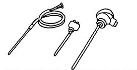
What are the types and characteristics of temperature sensors for Controllers?
Refer to the following table.
What is "Auto-tuning"?
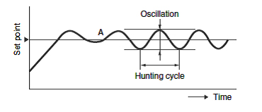
The PID constant values and combinations that are used for temperature control depend on the characteristics of the controlled object. A variety of conventional methods that are used to obtain these PID constants have been suggested and implemented based on actual control temperature waveforms. Auto-tuning methods make it possible to obtain PID constants suitable to a variety of controlling objects. One typical method is the limit cycle method.
Limit Cycle MethodON/OFF control begins from start point A in this method. Then obtain the PID constants from the hunting cycle T and oscillation D.
PID constants calculated in auto-tuning operation normally do not cause problems except for some particular applications. In those cases, refer to the following diagrams to readjust the constants.
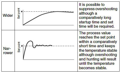
(1) Response to Change in the Proportional Band
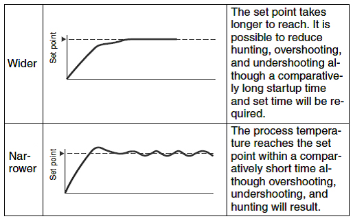
(2) Response to Change in Integral Time
(3) Response to Change in Derivative Time
Can manual operation be used when the temperature controllers are in ON/OFF control mode?
No, it cannot.
Manual operation can be used only when PID control is selected.
See whether you can change to PID contro
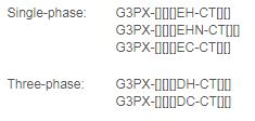
What wiring should be used between a Temperature Controller and the G3PX Power Controllers?
Controlling with a 4 to 20-mA-output Temperature Controller
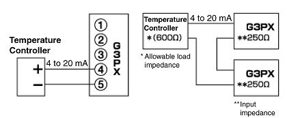
Note: Up to 2 drivable G3PX and a current output Temperature Controller can be used. This is restricted, however, to Temperature Controllers with an allowable load impedance of 600 O.
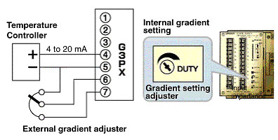
Note: The gradient can be changed using either the internal or external gradient setting using the external adjuster.
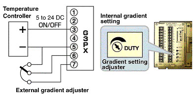
Note: The gradient can be changed using either the internal or external gradient setting.
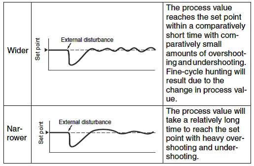
Why does E5[]N Basic-type Digital Temperature Controllers overshoot or undershoot?
The proportional band is too narrow and the P constant is too small.
The integral time is too short and the I constant is too small.
The derivative time is too long and the D constant is too large.
It is in ON/OFF control mode.
The control cycle is too long for a control system with fast thermal response.
The overlap band setting is mistakenly set for a dead band setting in heating and cooling control.
Applicable models: E5CN, E5GN, E5EN, and E5AN
Why doesn't the temperature of E5[]N Basic-type Digital Temperature Controllers rise or fall?
The load is not connected to the correct control output terminals.
Wires are not connected to the correct terminals or load polarity.
There is insufficient contact with the terminals because the terminal screws are loose.
The load power supply is OFF.
The heater has burnt out or deteriorated.
The heat capacity of the heater is insufficient for the load.
The overheating prevention device is not operating.
The reverse/forward operation setting in the Initial Setting Level is incorrect.
The PID constants are not suitable.
The RUN/STOP mode in the Operating Level is set to STOP.
Applicable models: E5CN, E5GN, E5EN, and E5AN
What happens if the Temperature Sensor terminals are connected with the wrong polarity?
The measured temperature will not be displayed properly.
If the polarity is connected in reverse, the Temperature Controllers will display a falling temperature when the temperature is actually rising.
If the polarity between A and B are reversed, "S.Err" will be displayed. There is no polarity between B and B.
Make sure that the polarity and terminals are correctly connected.
What happens when the Controllers are in STOP mode before control is started?
There will be no control outputs.
Set the RUN/STOP settings to RUN.
Outputs other than the control outputs (i.e., alarms) will be output.
What happens if the thermocouple lead wires or compensating lead wires are too long?
The lead wire resistance increases and the temperature displayed will be higher than the actual temperature. Make sure that the thermocouple lead wires or compensating lead wires are not affected by lead wire resistance.
Use thick wires as compensating lead wires.
Change the wiring location to shorten the lead wires.
What happens to the control output when the Sensor of E5C2 Temperature Controllers fails?
The status of the control output depends on the type of Temperature Sensors and the type of error.
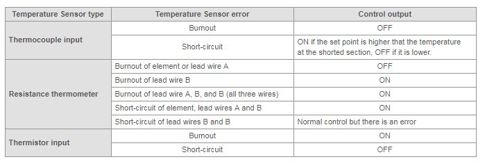
There is no way of sending notification of an input error to E5C2. Check the inputs if abnormal operation is detected.
Applicable models: E5C2
What is a substitute product for E5C4 Digital Temperature Controllers with digital settings and a digital display?
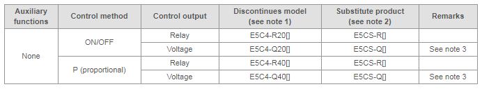
Note:
1.The [] in E5C4 model number indicates the type of input temperature sensor. It is "K" for the CA Thermocouple, "J" for the IC Thermocouple, and "P" for the Pt100 Resistance Thermometer.
2.The [] in E5CS Temperature Controllers model number indicates the type of input temperature sensor. It is "KJ" for a thermocouple, and "P" for a resistance thermometer. Select a model that is suitable for the temperature sensor being used or that is going to be used. Specify whether it is a type K or J thermocouple, or a JPt100 (old JIS) or Pt100 (new JIS) resistance thermometer using the Temperature Controller internal settings.
3.The control output voltage of E5C4 was 5 VDC, whereas it is 12 VDC for the substitute product. However, the voltage output is often connected to an Solid-state Relays, and the Solid-state Relays rated input voltage is often 5 to 24 VDC, therefore it could be used without modification. Nonetheless it is better to check the input conditions of the connected device.
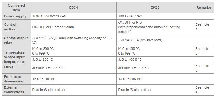
Note:
1.Generally PID control has better control characteristics than P control, but if the desired control characteristics cannot be obtained, see whether E5CN-U Basic-type Digital Temperature Controllers can be used to obtain the desired control characteristics. E5CN-U can force the I and D constants to zero, whereas E5CS cannot.
An 11-pin connecting socket is required for E5CN-U, and the wiring will need to be changed.
2.For E5C4, the model depends on the temperature range and type of input temperature sensor, whereas for E5CS there are only two types, the thermocouple (KJ) and the resistance thermometer (P). The temperature range and type of input temperature sensor can be specified using the Temperature Controller internal settings.
3.The Pt100 Resistance Thermometers are different for models before and after the 1989 JIS modifications. Models before the JIS modifications are the JPt100, and models after are the Pt100. E5C4 supports only JPt100, but E5CS supports both the JPt100 and JPt100. Specify which one you are using in the Temperature Controller settings.
4.External connections are compatible. There is no need to change the wiring.
What should I use to extend the lead wires of the platinum resistance thermometer?
Use commercially available lead wires. Make sure that the three lead wires for extension have the same resistance and are the same length.
Note:Extension lead wires are not available from OMRON.
What power supply should be used for ES2-THB Temperature/Humidity Sensors and ES2-HB Humidity Sensors?
A 24-VDC power supply with a maximum ripple voltage of 2% p-p.
See whether the 24 VDC Output Power Supply Unit can be used for your application.
ES2-THB and ES2-HB consume less than 10 mA of current.
Select a Power Supply Unit with sufficient capacity for the number of Sensors connected.
Example:
S8VS-01524 Switch Mode Power Supplies (Input: 100 to 240 VAC, Output: 24 VDC, 0.65 A)
S82K-00324 Switch Mode Power Supplies (Input: 100 to 240 VAC, Output: 24 VDC, 0.13 A)
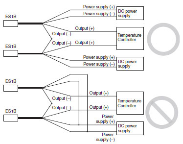
Can ES1B Infrared Thermosensors measure the temperature difference between two locations?
Yes. Refer to the following connections diagram.
 Automation Systems
  Motion & Power Solutions
  Safety, Vision and IDENT
  Sensing Solutions
  Control Components
  Switching & Accessories
  Switchgear and Trolley Systems
  Process Weighing
  LED Lighting
  Omron
Omron
 Mitsubishi
 Delta
Delta
 Autonics
 Inno
Inno
 Honeywell
 Novotechnik
 Orientalmotor
 Microscan
 IPA
IPA
 Technomech
 Intech
 IOT & Traceability
 Project & Panel Engg.
 Application Case Studies
 Solutions by Industry
 Solutions by Process
 Solutions by Product
 Corporate Information
 Company Profile
 Quality Policy
 Mission Statement
 Chairman's Message
 Intech Group Companies
