Automation Systems
  Motion & Power Solutions
  Safety, Vision and IDENT
  Sensing Solutions
  Control Components
  Switching & Accessories
  Switchgear and Trolley Systems
  Process Weighing
  LED Lighting
  Omron
Omron
 Mitsubishi
 Delta
Delta
 Autonics
 Inno
Inno
 Panasonic
 Novotechnik
 Orientalmotor
 Microscan
 IPA
IPA
 Technomech
 Intech
 Honeywell
 IOT & Traceability
 Project & Panel Engg.
 Application Case Studies
 Solutions by Industry
 Solutions by Process
 Solutions by Product
 Youtube Videos
 Corporate Information
 Company Profile
 Quality Policy
 Mission Statement
 Chairman's Message
 Intech Group Companies

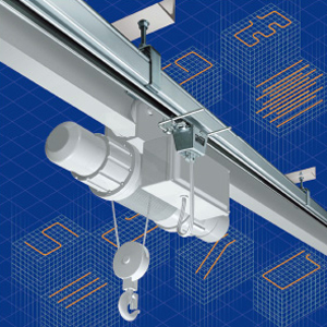
Compact Industrial SCARA
Compact Industrial Robot with light weight space saving arm. Its high speed operation is best suited for pick and place, labelling, tracking
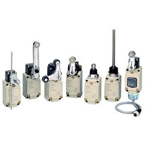

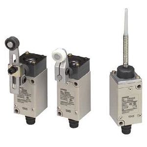
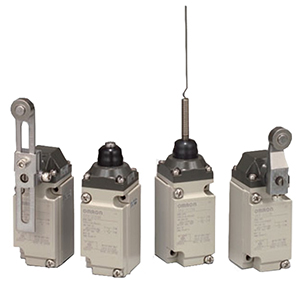
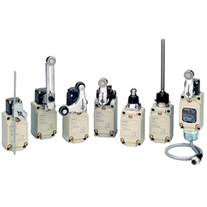
You can select the optimum product for the workpiece shape and movement from a variety of actuators, including Roller Lever, Plunger, Flexible Rod, and Fork Lock Lever Switches.
Airtight Switches, Hermetic Switches, Heat-resistant Switches, Low-temperature Switches, Corrosion-proof Switches, and Weather-proof Switches are available.
You can select the model based on the onsite environment.
Uses stainless steel and plastic materials that prevent the adhesion of spatter.
They can be used to reduce problems caused by zinc power generated during welding.
A mechanical durability of over 30 million cycles is achieved by improving slidability and the wear resistance of the head.
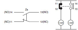
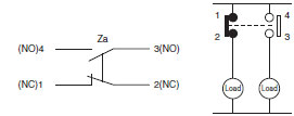
The two-circuit double-break structure ensures circuit braking.
• Basic/Retention type Switches (WL-N)
• High-sensitivity/High-precision Switches (WL)
A neon lamp or LED indicates the operating status. This makes startup checks and maintenance easy.
Direct-wire types and pre-wired types are available for easy replacement of limit switches.
| Item |
Rated voltage (V) |
Non-inductive load (A) | Inductive load (A) | |||||||
|---|---|---|---|---|---|---|---|---|---|---|
| Resistive load | Lamp load | Inductive load | Motor load | |||||||
| NC | NO | NC | NO | NC | NO | NC | NO | |||
| Basic | AC |
125 250 500 |
10 10 10 |
3 2 1.5 |
1.5 1 0.8 |
10 10 3 |
5 3 1.5 |
2.5 1.5 0.8 |
||
| DC |
8 14 30 125 250 |
10 10 6 0.8 0.4 |
6 6 4 0.2 0.1 |
3 3 3 0.2 0.1 |
10 10 6 0.8 0.4 |
6 6 4 0.2 0.1 |
||||
|
High-sensitivity High-precision *1 |
AC |
125 250 |
5 5 |
---- | ---- | ---- | ||||
| DC |
125 250 |
0.4 0.2 |
---- | ---- | ---- | |||||
Note: 1. The above figures are for steady-state currents.
2. Inductive loads have a power factor of 0.4 min. (AC) and a time constant of 7 ms max. (DC).
3. A lamp load has an inrush current of 10 times the steady-state current.
4. A motor load has an inrush current of 6 times the steady-state current.
| Inrush current | NC | 30 A max. (15 A max. *1) |
|---|---|---|
| NO | 20 A max. (10 A max. *1) |
*1. For High-sensitivity and High-precision Switches.
| Operating characteristics | Minimum applicable load |
|---|---|
| Basic | 5 VDC 1 mA, resistive load, P level |
|
High-sensitivity, High-precision |
5 VDC 160 mA, resistive load, N level reference value |
| Rated voltage (V) | Rated current (A) - Resistive load |
|---|---|
| AC125 | 0.1 |
| DC 30 |
Note: The load is a resistive load.
Operation in the following ranges will produce optimum performance.
| Recommended load range |
5 to 30 VDC 0.16 to 100 mA |
|---|
| Operating characteristics | Minimum applicable load |
|---|---|
|
High-sensitivity, High-precision |
5 VDC 1 mA N level reference value |
| Item |
Rated voltage (V) |
Non-inductive load (A) | Inductive load (A) | ||||||
|---|---|---|---|---|---|---|---|---|---|
| Resistive load | Lamp load | Inductive load | Motor load | ||||||
| NC | NO | NC | NO | NC | NO | NC | NO | ||
| Basic | AC 115 | 3 | 3 | 1.5 | 3 | 3 | 2.5 | ||
|
DC 12 DC 24 DC 115 |
3 3 0.8 |
3 3 0.2 |
3 3 0.8 |
3 3 0.2 |
|||||
|
High-sensitivity High-precision *1 |
AC 115 | 3 | ---- | ---- | ---- | ||||
| DC 115 | 0.4 | ---- | ---- | ---- | |||||
Note: 1. The above figures are for steady-state currents.
2. Inductive loads have a power factor of 0.4 min. (AC) and a time constant of 7 ms max. (DC).
3. A lamp load has an inrush current of 10 times the steady-state current.
4. A motor load has an inrush current of 6 times the steady-state current.
| Inrush current | NC | 3 A max. |
|---|---|---|
| NO | 3 A max. |
| Operating characteristics | Minimum applicable load |
|---|---|
| Basic | 5 VDC 1 mA, resistive load, P level |
|
High-sensitivity, High-precision |
5 VDC 160 mA, RESISTIVE Load, N level reference value |
| Model | Max. rated voltage (V) | Leakage current (mA) | |
|---|---|---|---|
|
WL-LE-N WL-LE |
Neon lamp | 125 VAC | Approx. 0.6 |
| 250 AC | Approx. 1.9 | ||
|
WL-LD-N WL-LW-N WL-LD |
LED | 10 to 24 VAC/DC | Approx. 0.4 |
| 115 VAC/DC | Approx. 0.5 | ||
| Degree of protection | IP67 | |
|---|---|---|
| Durability *1 | Mechanical | 15,000,000 operations min. *2 |
| Electrical | 750,000 operations min. (3 A at 250 VAC, resistive load) *3 | |
| Operating speed | 1 mm to 1 m/s (for WLCA2-N) | |
|
Operating frequency |
Mechanical | 120 operations/minute min. |
| Electrical | 30 operations/minute min. | |
| Rated frequency | 50/60 Hz | |
| Insulation resistance | 100 MΩ min. (at 500 VDC) | |
| Contact resistance | 25 mΩ max. (initial value for the built-in switch when tested alone) | |
|
Dielectric strength |
Between terminals of the same polarity | 1,000 VAC (600 VAC) 50/60 Hz 1 min |
| Between currentcarrying metal part and ground | 2,200 VAC (1,500 VAC) 50/60 Hz 1 min *5 | |
| Between each terminal and non-currentcarrying metal part | 2,200 VAC (1,500 VAC) 50/60 Hz 1 min *5 | |
|
Vibration resistance |
Malfunction | 10 to 55 hz, 1.5-mm double amplitude *6 |
|
Shock resistance |
Destruction | 1,000 m/s2 max. |
| Malfunction | 300 m/s2 *6 | |
| Ambient operating temperature | -10 to +80°C (with no icing) *7 | |
| Ambient operating humidity | 35% to 95% RH | |
| Weight | Approx. 255 g (for WLCA2-N) | |
Note: 1. The above figures are initial values.
2. The figures in parentheses for dielectric strength are those for the high-sensitivity and high-precision switches models.
*1. The values are calculated at an operating temperature of +5°C to +35°C, and an operating humidity of 40% to 70% RH. Contact your OMRON sales representative for more detailed information on other operating environments.
*2. High-sensitivity models and Flexible Rod models: 10 million operations min.500,000 operations min. for Weather-resistant models.
*3. High-sensitivity models, High-precision models, and Weatherproof models are 500,000 operations min.Micro-load models are 1 million operations min.Contact your OMRON representative for information on Airtight models and Hermetic models.
*4. Micro-load models and Weather-proof models are 50 mΩ or less (default value, built-in switch only).
*5. Sensor I/O connector type is 1,500 V.
*6. Except Flexible Rod models. Micro-load models are 200 m/s2 max.
*7. For low-temperature models this is –40°C to +40°C (with no icing).For heat-resistant models the range is +5°C to +120°C.
| Item | Rated voltage (V) | Non-inductive load (A) | Inductive load (A) | |||||||
|---|---|---|---|---|---|---|---|---|---|---|
| Resistive load | Lamp load | Inductive load | Motor load | |||||||
| NC | NO | NC | NO | NC | NO | NC | NO | |||
| WL[]-LES-N | AC |
125 250 |
10 (5) 10 (5) |
3 2 |
1.5 1 |
10 10 |
5 3 |
2.5 1.5 |
||
| WL[]-LDS-N | AC | 115 | 10 (5) | 3 | 1.5 | 10 | 5 | 2.5 | ||
| DC |
12 24 115 |
10 6 0.8 (0.4) |
6 4 0.2 |
3 3 0.2 |
10 6 0.8 |
6 4 0.2 |
||||
Note: 1. The above figures are for steady-state currents.
2. Inductive loads have a power factor of 0.4 min. (AC) and a time constant of 7 ms max. (DC).
3. A lamp load has an inrush current of 10 times the steady-state current.
4. A motor load has an inrush current of 6 times the steady-state current.
5. The figures in parentheses for resistive load are those for the high-sensitivity and high-precision switches models.
| Inrush current | NC | 30 A max. (15 A max. *) |
|---|---|---|
| NO | 20 A max. (10 A max. *) |
* For High-sensitivity and High-precision Switches.
| Operating characteristics | Minimum applicable load |
|---|---|
| Basic | 5 VDC 1 mA, resistive load, P level |
|
High-sensitivity, High-precision |
5 VDC 160 mA, Resistive load, N level reference value |
| Item |
Rated voltage (V) |
Non-inductive load (A) | Inductive load (A) | |||||||
|---|---|---|---|---|---|---|---|---|---|---|
| Resistive load | Lamp load | Inductive load | Motor load | |||||||
| NC | NO | NC | NO | NC | NO | NC | NO | |||
| Basic | AC | 115 | 3 | 3 | 1.5 | 3 | 3 | 2.5 | ||
| DC |
12 24 115 |
3 3 0.8 |
3 3 0.2 |
3 3 0.8 |
3 3 0.2 |
|||||
|
High-sensitivity High-precision *1 |
AC | 115 | 3 | ---- | ---- | ---- | ||||
| DC | 115 | 0.4 | ---- | ---- | ---- | |||||
Note: 1. The above figures are for steady-state currents.
2. Inductive loads have a power factor of 0.4 min. (AC) and a time constant of 7 ms max. (DC).
3. A lamp load has an inrush current of 10 times the steady-state current.
4. A motor load has an inrush current of 6 times the steady-state current.
| Inrush current | NC | 3 A max. |
|---|---|---|
| NO | 3 A max. |
| Operating characteristics | Minimum applicable load |
|---|---|
| Basic | 5 VDC 1 mA, resistive load, P level |
|
High-sensitivity, High-precision |
5 VDC 160 mA, Resistive load, N level reference value |
| Model | Max. rated voltage (V) | Leakage current (mA) | |
|---|---|---|---|
|
WL-LES-N WL-LE |
Neon lamp | 125 VAC | Approx. 0.6 |
| 250 VAC | Approx. 1.9 | ||
|
WL-LDS-N WL-LD |
LED | 10 to 24 VAC/DC | Approx. 0.4 |
| 115 VAC/DC | Approx. 0.5 | ||
| Degree of protection | IP67 | |
|---|---|---|
| Durability *1 | Mechanical | 15,000,000 operations min. *2 |
| Electrical | 750,000 operations min. (3 A at 250 VAC, resistive load) *3 | |
| Operating speed | 1 mm to 1 m/s (in case of WLCA2-LDS-N) | |
|
Operating frequency |
Mechanical | 120 operations/minute min. |
| Electrical | 30 operations/minute min. | |
| Rated frequency | 50/60 Hz | |
| Insulation resistance | 100 MΩ min. (at 500 VDC) | |
| Contact resistance | 25 mΩ max. (initial value for the built-in switch) | |
|
Dielectric strength |
Between terminals of the same polarity |
1,000 VAC (600 VAC) 50/60 Hz 1 min |
|
Between currentcarrying metal part and ground |
2,200 VAC (1,500 VAC) 50/60 Hz 1 min *4 | |
|
Between each terminal and non- currentcarrying metal part |
2,200 VAC (1,500 VAC) 50/60 Hz 1 min *4 | |
|
Vibration resistance |
Malfunction | 10 to 55 hz, 1.5-mm double amplitude |
|
Shock resistance |
Destruction | 1,000 m/s2 max. |
| Malfunction | 300 m/s2 max. | |
| Ambient operating temperature | -10 to +80°C (with no icing) | |
| Ambient operating humidity | 35% to 95% RH | |
| Weight | Approx. 255 g (in case of WLCA2-LDS-N) | |
Note: 1. The above figures are initial values.
2. The figures in parentheses for dielectric strength are those for the high-sensitivity and high-precision switches
models.
*1. The values are calculated at an operating temperature of +5°C to +35°C, and an operating humidity of 40% to 70% RH.
Contact your OMRON sales representative for more detailed information on other operating environments.
*2. High-sensitivity models are 10 million operations min.
*3. High-sensitivity models and High-precision models are 500,000 operations min.
Micro-load models are 10 million operations min.
Contact your OMRON representative for information on Airtight switches.
*4. Sensor I/O connector type is 1,500 V.
| Item |
Rated voltage (V) |
Non-inductive load (A) | Inductive load (A) | |||||||
|---|---|---|---|---|---|---|---|---|---|---|
| Resistive load | Lamp load | Inductive load | Motor load | |||||||
| NC | NO | NC | NO | NC | NO | NC | NO | |||
| Basic | AC | 115 | 10 | 3 | 1.5 | 10 | 5 | 2.5 | ||
| DC |
12 24 115 |
10 6 0.8 |
6 4 0.2 |
3 3 0.2 |
10 6 0.8 |
6 4 0.2 |
||||
|
High-sensitivity High-precision * |
AC | 115 | 5 | — | — | — | ||||
| DC | 115 | 0.4 | — | — | — | |||||
Note: 1. The above figures are for steady-state currents.
2. Inductive loads have a power factor of 0.4 min. (AC) and a time constant of 7 ms max. (DC).
3. A lamp load has an inrush current of 10 times the steady-state current.A motor load has an inrush current of 6 times the steady-state current.
| Inrush current | NC | 30 A max. (15 A max. *) |
|---|---|---|
| NO | 20 A max. (10 A max. *) |
* For High-sensitivity and High-precision Switches.
| Operating characteristics | Minimum applicable load |
|---|---|
| Basic | 5 VDC 1 mA, resistive load, P level |
|
High-sensitivity, High-precision |
5 VDC 160 mA, Resistive load, N level reference value |
| Item |
Rated voltage (V) |
Non-inductive load (A) | Inductive load (A) | |||||||
|---|---|---|---|---|---|---|---|---|---|---|
| Resistive load | Lamp load | Inductive load | Motor load | |||||||
| NC | NO | NC | NO | NC | NO | NC | NO | |||
| Basic | AC | 115 | 3 | 3 | 1.5 | 3 | 3 | 2.5 | ||
| DC |
12 24 115 |
3 3 0.8 |
3 3 0.2 |
3 3 0.8 |
3 3 0.2 |
|||||
|
High-sensitivity High-precision *1 |
AC | 115 | 3 | ---- | ---- | ---- | ||||
| DC | 115 | 0.4 | ---- | ---- | ---- | |||||
Note: 1. The above figures are for steady-state currents.
2. Inductive loads have a power factor of 0.4 min. (AC) and a time constant of 7 ms max. (DC).
3. A lamp load has an inrush current of 10 times the steady-state current.
4. A motor load has an inrush current of 6 times the steady-state current.
| Inrush current | NC | 3 A max. |
|---|---|---|
| NO | 3 A max. |
| Operating characteristics | Minimum applicable load |
|---|---|
| Basic | 5 VDC 1 mA, resistive load, P level |
|
High-sensitivity, High-precision |
5 VDC 160 mA, Resistive load, N level reference value |
| Model | Max. rated voltage (V) | Leakage current (mA) | |
|---|---|---|---|
|
WL-LD-N WL-LW-N WL-LD |
LED | 10 to 24 VAC/DC | Approx. 0.4 |
| 115 VAC/DC | Approx. 0.5 | ||
| Degree of protection | IP67 | |
|---|---|---|
|
Durability *1 |
Mechanical | 30,000,000 operations min. |
| Electrical |
30,000,000 operations min. (10 mA at 24 VDC, resistive load) 750,000 operations min. (3 A at 115 VAC, resistive load), but for high- precision models: High-sensitivity and High-precision Switches: 500,000 operations min. |
|
| Operating speed | 1 mm to 1 m/s (in case of WLMCA2-LD-N) | |
|
Operating frequency |
Mechanical | 120 operations/min. |
| Electrical | 30 operations/min. | |
| Rated frequency | 50/60 Hz | |
| Insulation resistance | 100 MΩ min. (at 500 VDC) | |
| Contact resistance | 25 mΩ max. (initial value for the built-in switch when tested alone) *2 | |
|
Dielectric strength (50/60 Hz for 1 min) |
Between terminals of the same polarity |
1,000 VAC (600 VAC), 50/60 Hz 1 min |
|
Between currentcarrying metal part and ground |
2,200 VAC (1,500 VAC) 50/60 Hz 1 min *3 | |
|
Between each terminal and non-currentcarrying metal part |
2,200 VAC (1,500 VAC) 50/60 Hz 1 min *3 | |
|
Vibration resistance |
Malfunction | 10 to 55 Hz, 1.5-mm double amplitude |
|
Shock resistance |
Destruction | 1,000 m/s2 max. |
| Malfunction | 300 m/s2 max. *4 | |
| Ambient operating temperature | -10 to +80°C (with no icing) | |
| Ambient operating humidity | 35% to 95% RH | |
| Weight | Approx. 255 g (in case of WLMCA2-LD-N) | |
Note: 1. The above figures are initial values.
2. The figures in parentheses for dielectric strength are those for the high-sensitivity and high-precision switches
models.
*1. The values are calculated at an operating temperature of +5°C to +35°C, and an operating humidity of 40% to 70% RH.
Contact your OMRON sales representative for more detailed information on other operating environments.
*2. For microload models, the contact resistance is 50 mΩ max. (initial value for built-in switch).
*3. Sensor I/O connector models are 1,500 V.
*4. Micro-load models are 200 m/s2 max.
| Agency | Standard | File No. | Approved models |
|---|---|---|---|
| UL | UL508 |
Contact your OMRON representative for information |
Contact your OMRON representative for information |
| CSA cUL | CSA C22.2 No.14 | ||
| TÜV Rheinland | EN60947-5-1 | ||
| CCC (CQC) | GB14048.5 |
| Specifications | Approved Standards | ||
|---|---|---|---|
| Indicator | Sensor I/O connectors | Item | |
| No indicator | No Connector | Basic Switches |
A600 1 A, 125 VDC |
| High-sensitivity or high-precision | A600 | ||
| Pre-wired Connector (AC) | Basic, high-sensitivity or high-precision |
C300 3 A, 250 VAC |
|
|
Pre-wired Connector (DC) Direct-wired Connector (DC) |
Basic Switches | 1 A, 125 VDC | |
| High-sensitivity or high-precision | 0.8 A, 125 VDC | ||
| Neon lamp | No Connector | Basic Switches |
A300 10 A, 250 VAC |
| High-sensitivity or high-precision | |||
| Pre-wired Connector (AC) | Basic, high-sensitivity or high-precision |
C300 3 A, 250 VAC |
|
| LED | No Connector | Basic Switches |
A150 10 A, 115 VAC 1 A, 115 VDC |
| High-sensitivity or high-precision |
A150 10 A, 115 VAC 0.8 A, 115 VDC |
||
| Pre-wired Connector (AC) | Basic, high-sensitivity or high-precision |
C150 3 A, 115 VAC |
|
|
Pre-wired Connector (DC) Direct-wired Connector (DC) |
Basic Switches | 1 A, 115 VDC | |
| High-sensitivity or high-precision | 0.8 A, 115 VDC | ||
| Rated voltage | Energizing current | Current (A) | Volt-ampere (VA) | ||
|---|---|---|---|---|---|
| Make | Break | Make | Break | ||
|
120 VAC 240 VAC 480 VAC 600 VAC |
10 A |
60 30 15 12 |
6 3 1.5 1.2 |
7,200 | 720 |
| Rated voltage | Energizing current | Current (A) | Volt-ampere (VA) | ||
|---|---|---|---|---|---|
| Make | Break | Make | Break | ||
|
120 VAC 240 VAC |
2.5 A |
15 7.5 |
1.5 0.75 |
1,800 | 180 |
| Rated voltage | Energizing current | Current (A) | Volt-ampere (VA) | ||
|---|---|---|---|---|---|
| Make | Break | Make | Break | ||
|
120 VAC 240 VAC |
10 A |
60 30 |
6 3 |
7,200 | 720 |
| Rated voltage | Energizing current | Current (A) | Volt-ampere (VA) | ||
|---|---|---|---|---|---|
| Make | Break | Make | Break | ||
| 120 VAC | 10 A | 60 | 6 | 7,200 | 720 |
| Rated voltage | Energizing current | Current (A) | Volt-ampere (VA) | ||
|---|---|---|---|---|---|
| Make | Break | Make | Break | ||
| 120 VAC | 2.5 A | 15 | 1.5 | 1,800 | 180 |
(Certification Only for Switches with Ground Terminals and DC Switches with Connectors)
| Authentication conditions | Specification | |||||
|---|---|---|---|---|---|---|
| With ground terminals | With DC Connector | |||||
| No indicator | Neon lamp | LED | ||||
| Working load category | AC-15 | DC-12 | AC-15 | AC-15 | DC-12 | DC-12 |
| Rated working voltage (Ue) | 250 V | 48 V | 250 V | 115 V | 48 V | 48 V |
| Rated working current (Ie) | 2 A | |||||
| Conditional short-circuit current | 100 A | |||||
| Short-circuit protective device (SCPD) | 10 A, fuse type gG | |||||
| Rated insulation voltage (Ui) | 250 V | 48 V | ||||
| Rated impulse dielectric strength (Uimp) | 4 kV | 800 V | ||||
| Pollution degree | 3 | |||||
| Electric shock protection class | Class I | Class III | ||||
| Authentication conditions | Specification | ||||||
|---|---|---|---|---|---|---|---|
| No indicator |
Neon lamp |
LED |
With DC Connector |
With AC Connector |
|||
| Working load category | AC-15 | DC-13 | AC-15 | AC-15 | DC-13 | DC-13 | AC-15 |
| Rated working voltage (Ue) | 250 V | 48 V | 250 V | 250 V | 48 V | 48 V | 250 V |
| Rated working current (Ie) | 2 A | ||||||
| Conditional short-circuit current | 1000 A | ||||||
| Short-circuit protective device (SCPD) | 10 A, fuse type gG | ||||||
| Rated insulation voltage (Ui) | 250 V | ||||||
(Unit: mm)
Note: Unless otherwise indicated, a tolerance of ±0.4 mm applies to all dimensions.
Roller lever R38
WLCA2-N
WLCA2-2-N
WLCA2-2N-N
Roller lever R50
WLCA2-7-N
Roller lever R63
WLCA2-8-N
Adjustable roller lever
WLCA12-N
WLCA12-2-N
WLCA12-2N-N
Adjustable rod lever 25 to 140 mm
WLCL-N
WLCL-2-N
WLCL-2N-N
Adjustable rod lever
WLCAL4-N
Rod spring lever
WLCAL5-N
Roller lever R38
WLG2
WL01G2
Adjustable rod lever 25 to 140 mm
WLGL
WL01GL
Adjustable Roller Lever
WLG12
WL01G12
Roller lever R38
WLGCA2
WL01GCA2
Sealed top plunger
WLD18-N
Horizontal plunger
WLSD-N
Sealed top-roller plunger
WLD28-N
Horizontal-roller plunger
WLSD2-N
Sealed top-ball plunger
WLD38-N
Horizontal-ball plunger
WLSD3-N
Top-roller plunger
WLD2-N
Coil spring
WLNJ-N
Coil Spring (Multi-wire)
WLNJ-30-N
Resin rod
WLNJ-2-N
Steel wire
WLNJ-S2-N
General-purpose
WLCA32-41-N
WLCA32-42-N
WLCA32-43-N
WLCA32-44-N
The WLCA32-41-N is shown in the following diagram.
Roller lever R38
General-purpose Models
WLCA2-LD-N
WLCA2-LE-N
(For details about applicable cables, refer to Connecting Sensor I/O Connectors Cable and Socket on Data Sheet.)
Roller lever R38
Direct-wire Connector type
WLCA2-LDK13-N
Roller lever R38
Pre-wired Connector type
WLCA2-LD-M1J-N
Note: The models with operation indicators are shown in the above diagrams.
Roller lever R38
Direct-wire Connector type
High-sensitivity: WLG2
High-precision: WLGCA2
Roller lever R38
Pre-wired Connector type
High-sensitivity: WLG2
High-precision: WLGCA2
Roller lever R38
Screw terminal type
WLCA2-[]S-N
Roller lever R38
Pre-wired Connector type
WLCA2-[]S-M1J-1-N
Note: The models with operation indicators are shown in the above diagrams.
Roller lever R38
Screw terminal type
WLG2-[]S
WLGCA2-[]S
Roller lever R38
Pre-wired Connector type
WLG2-[]S-M1J *
WLGCA2-[]S-M1J *
* External dimensions are the same even for different core wires.
Sealed top-roller plunger
Screw terminal type
WLD28-[]S-N
Sealed top-roller plunger
Pre-wired Connector type
WLD28-[]S-M1J-1-N
Note: The models with operation indicators are shown in the above diagrams.
Roller lever R38
Screw terminal type
WLMCA2-LD-N
Roller lever R38
Direct-wire Connector type
WLMCA2-LDK13-N
Roller lever R38
Pre-wired Connector type
WLMCA2-LD-M1J-N
Note: The models with operation indicators are shown in the above diagrams.
Roller lever R38
Screw terminal type
WLMG[]-LD
Roller lever R38
Direct-wire Connector type
WLMG[]-LD[]
Roller lever R38
Pre-wired Connector type
WLMG[]-LD[]
WL-1A100
Standard Lever
WL-1A115
Resin Roller
WL-1A400
Bearing Roller
WL-1A118
Nylon Roller:
Roller Width: 30 mm
WL-1A105
Double Nuts
WL-1A103S
Spatter Prevention
WL-1A200
Lever Length: 50
Roller Width: 15
WL-1A300
Lever Length: 63
WL-2A100
WL-2A111
Resin Roller
WL-2A107
Double Nuts
WL-2A108
Resin Roller
WL-2A122
WL-2A106
WL-2A130
WL-2A104
WL-2A110
WL-2A105
WL-1A106
WL-1A110
WL-4A100
WL-4A201
WL-3A100
WL-3A106
Double Nut
WL-3A108
WL-3A200
WL-3A203
WL-4A112
WL-2A129
WL-5A101
WL-5A103
WL-5A105
Note: When using the adjustable roller (rod) lever, make sure that the lever is facing downwards.Use caution, as telegraphing (the Switch turns ON and OFF repeatedly due to inertia) may occur.
As for models without an O-ring, please use sealing tape with SC Connectors.
Metal Models without O-ring
G½
SC-21 to 25
Metal Models with O-ring
G½
SC-1M to 5M
Metal Models without O-ring
½-14NPT
(U.S.-standard screws)
SC-1PT to 5PT
Resin Models
G½
SC-P2
Resin Models
Pg13.5
SC-P3
Resin Models
G½
SC-6
* Diameter of Part Marked with Asterisk