Automation Systems
  Motion & Power Solutions
  Safety, Vision and IDENT
  Sensing Solutions
  Control Components
  Switching & Accessories
  Switchgear and Trolley Systems
  Process Weighing
  LED Lighting
  Omron
Omron
 Mitsubishi
 Delta
Delta
 Autonics
 Inno
Inno
 Panasonic
 Novotechnik
 Orientalmotor
 Microscan
 IPA
IPA
 Technomech
 Intech
 Honeywell
 IOT & Traceability
 Project & Panel Engg.
 Application Case Studies
 Solutions by Industry
 Solutions by Process
 Solutions by Product
 Youtube Videos
 Corporate Information
 Company Profile
 Quality Policy
 Mission Statement
 Chairman's Message
 Intech Group Companies

Compact Industrial SCARA
Compact Industrial Robot with light weight space saving arm. Its high speed operation is best suited for pick and place, labelling, tracking
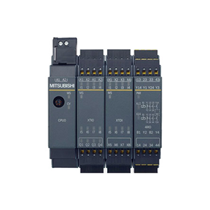

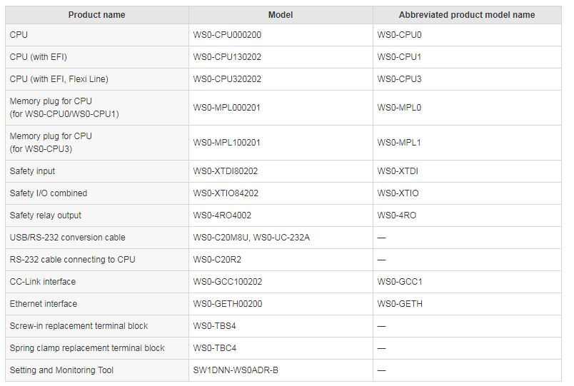
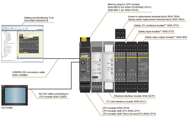
Safety controller MELSEC-WS Series
This compact safety controller complies with EN ISO 13849-1 Category 4/Ple and IEC 61508 SIL 3 safety standards. It is ideal for small to medium-scale safety control system. Safety I/O points can be extended to 144 points per CPU module according to the system configuration. Utilizing the dedicated setting and monitoring tool*1, setup and logic creation can be easily done.
MELSEC-WS Series system configuration
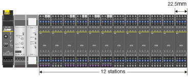
Flexible extensibility
Fast shut off function realizing a response time of 8 ms
Fast shut off function that enables the safety I/O module to shut off safety output without going through the CPU module realizes a response time of 8 ms. This system can shorten safety distances in the safety system.
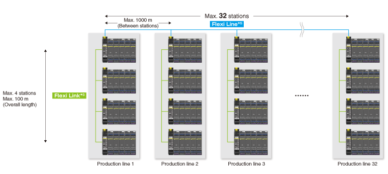
Flexi Line/Flexi Link
Safety communication network between safety controllers
Safety communications between safety controllers can be easily established at a low cost just by connecting the CPU modules with dedicated cables. Safety communication is realized without a dedicated network module, allowing utilization in various production site. In addition, coordination between multiple devices is possible, improving production system safety.
Safety control can be easily added to existing MELSEC PLCs (CC-Link/Ethernet)
Applicable functions with network interface
Connecting the safety controller to CC-Link, safety control can be performed with the existing MELSEC iQ-R/Q/L module. Furthermore, operation status and error status of the safety controller can be monitored with the existing MELSEC iQ-R/Q/L module. This helps quickly identifying the factor of emergency stop and faulty equipment.
Dedicated "Setting and Monitoring Tool*6" provides intuitive system configuration environment
■ Configuration
Hardware configuration can be easily and quickly done using a wide range of elements.
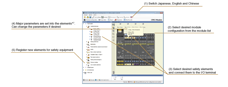
Make settings simply by drag-and-drop decision. Elements for safety devices of mitsubishi's partners are also available. Please contact your local Mitsubishi representative.
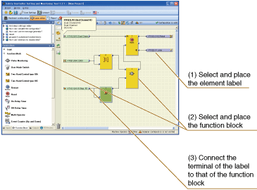
Logic Editor
Elements connected to the I/O terminal are automatically labeled, enabling logic creation easier using labels and function blocks.
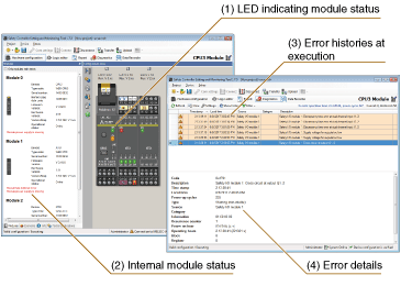
Diagnosis/monitor
Monitoring of the internal status of modules and error histories is possible.
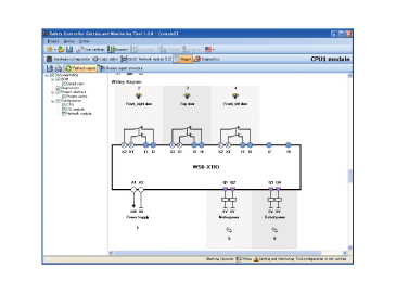
Report
The wiring diagram for I/O modules can be automatically created. Report such as error diagnosis can be created, printed, and saved as PDF.
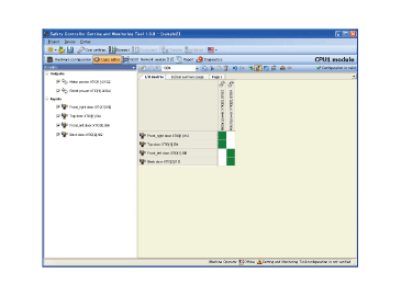
I/O matrix
The relation of inputs and outputs can be displayed as a matrix.
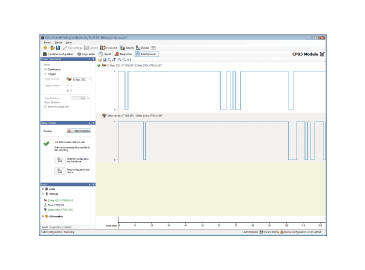
ON/OFF status of safety input signal and safety output signal processed by the safety controller can be stored.*8 Results recorded on the Setting and Monitoring Tool can also be viewed on the computer to utilize for troubleshooting.
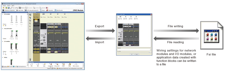
Import and export of logic
The connection settings to the I/O modules or application logic created with function blocks can be stored in a single setting file, and data can be read out of stored setting files.