Automation Systems
  Motion & Power Solutions
  Safety, Vision and IDENT
  Sensing Solutions
  Control Components
  Switching & Accessories
  Switchgear and Trolley Systems
  Process Weighing
  LED Lighting
  Omron
Omron
 Mitsubishi
 Delta
Delta
 Autonics
 Inno
Inno
 Panasonic
 Novotechnik
 Orientalmotor
 Microscan
 IPA
IPA
 Technomech
 Intech
 Honeywell
 IOT & Traceability
 Project & Panel Engg.
 Application Case Studies
 Solutions by Industry
 Solutions by Process
 Solutions by Product
 Youtube Videos
 Corporate Information
 Company Profile
 Quality Policy
 Mission Statement
 Chairman's Message
 Intech Group Companies

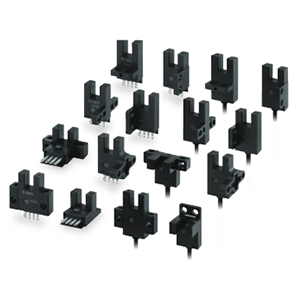
Compact Industrial SCARA
Compact Industrial Robot with light weight space saving arm. Its high speed operation is best suited for pick and place, labelling, tracking

last update: December 19, 2013
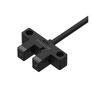
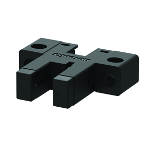
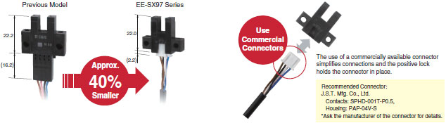
A built-in connector minimizes the shape and dimensional requirements. And wiring costs can be reduced by using commercially available connectors.
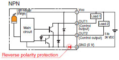
The built-in power supply reverse polarity protection protects against reverse connection of the power supply or outputs for safer operation at the assembly site.
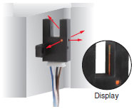
The indicator can be seen from up to four directions to enable installation in more locations.
Control output 2 on models with NPN outputs is protected from output overcurrents by a built-in thermal shutdown circuit.
All models provide both a light-ON and dark-ON output so that the output can be switched according to the application simply by changing the wiring.
last update: December 19, 2013
last update: August 06, 2013
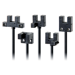
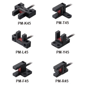
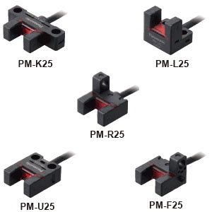
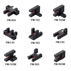
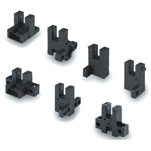
| Type | Standard | L-shaped | T-shaped,
slot center 7 mm |
Close-
mounting |
T-shaped,
slot center 10 mm |
F-shaped | R-shaped | |
|---|---|---|---|---|---|---|---|---|
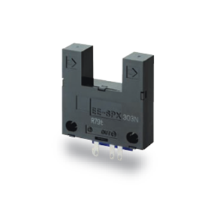
| NPN | EE-
SX970-C1 |
EE-
SX971-C1 |
EE-
SX972-C1 |
EE-
SX974-C1 |
EE-
SX975-C1 |
EE-
SX976-C1 |
EE-
SX977-C1 |
|
| PNP | EE-
SX970P- C1 |
EE-
SX971P- C1 |
EE-
SX972P- C1 |
EE-
SX974P- C1 |
EE-
SX975P- C1 |
EE-
SX976P- C1 |
EE-
SX977P- C1 |
|
| Sensing distance | 5 mm (slot width) | |||||||
| Sensing object | Opaque: 2 × 0.8 mm min. | |||||||
| Differential distance | 0.025 mm max. *1 | |||||||
| Light source (Peak
wavelength) |
Infrared LED with a peak wavelength of 940 nm | |||||||
| Indicator | Light indicator (orange LED) | |||||||
| Supply voltage | 5 to 24 VDC ±10%, ripple (p-p): 10% max. | |||||||
| Current consumption | 21 mA max. | |||||||
| Control output | Load power supply voltage: 5 to 24 VDC, Load current: 50 mA max., Off-state current: 0.5mA
max, 50 mA load current with a residual voltage of 1.0 V max., 5 mA load current with a residual voltage of 0.4 V max. |
|||||||
| Protection circuit | Power supply reverse polarity protection; output reverse polarity protection;
overcurrent protection (only OUT2 on models with NPN output) |
|||||||
| Response frequency | 1 kHz min. (3 kHz average) *2 | |||||||
| Ambient illumination | 1,000 lx max. with fluorescent light on the surface of the receiver | |||||||
| Ambient temperature
range |
Operating: -25 to 55°C Storage: -30 to 80°C (with no icing or condensation) | |||||||
| Ambient humidity
range |
Operating: 5% to 85% Storage: 5% to 95% (with no icing or condensation) | |||||||
| Vibration resistance
(Destruction) |
10 to 2,000 Hz 0.75-mm single amplitude (15-min periods, 10 cycles) each in X, Y, and Z
directions |
|||||||
| Shock resistance
(Destruction) |
Destruction: 500 m/s2 for 3 times each in X, Y, and Z directions | |||||||
| Degree of protection | IEC 60529 IP50 | |||||||
| Connecting method | Connector | |||||||
| Weight (Packed state) | Approx. 3 g | |||||||
| Materia | Case/Cover | Polybutylene terephthalate (PBT) | ||||||
| Emitter/
receiver |
Polycarbonate (PC) | |||||||
*1. The differential distance is the value when a sensing object is moved in a lateral direction to the slot.
*2. The response frequency was measured by detecting the following rotating disk.
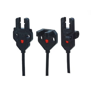
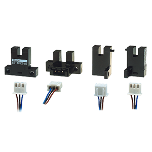
| Product | Connector with Cable | Connector with Robot Cable | |
|---|---|---|---|
| Model | EE-1017 | EE-1017-R | |
| Appearance |
|
||
| Contact resistance | 25 mΩ max. (at 10 mA DC and 20 mV max.) | ||
| Insertion strength | 20 N max. | ||
| Surplus strength | 1.5 N min. | ||
| Cable length | 1 m, 3 m | ||
| Ambient temperature range | -10 to +60°C | ||
| Materials | Housing | Nylon | |
| Contact | Phosphor bronze | ||
last update: August 06, 2013
last update: December 19, 2013
Tolerance class IT16 applies to dimensions in this datasheet unless otherwise specified.
last update: December 19, 2013