Automation Systems
  Motion & Power Solutions
  Safety, Vision and IDENT
  Sensing Solutions
  Control Components
  Switching & Accessories
  Switchgear and Trolley Systems
  Process Weighing
  LED Lighting
  Omron
Omron
 Mitsubishi
 Delta
Delta
 Autonics
 Inno
Inno
 Panasonic
 Novotechnik
 Orientalmotor
 Microscan
 IPA
IPA
 Technomech
 Intech
 Honeywell
 IOT & Traceability
 Project & Panel Engg.
 Application Case Studies
 Solutions by Industry
 Solutions by Process
 Solutions by Product
 Youtube Videos
 Corporate Information
 Company Profile
 Quality Policy
 Mission Statement
 Chairman's Message
 Intech Group Companies

Compact Industrial SCARA
Compact Industrial Robot with light weight space saving arm. Its high speed operation is best suited for pick and place, labelling, tracking
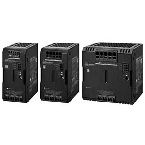

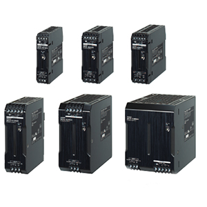
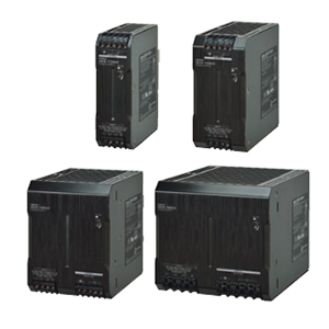
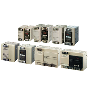
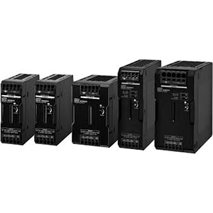
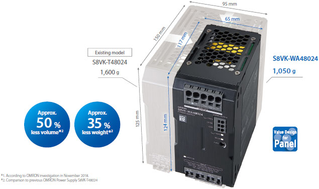
This high-capacity yet compact Power Supply requires only less than half the space of the existing models.
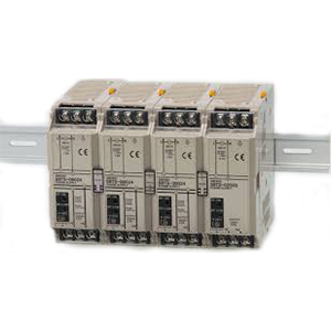
Side-by-side mounting possible.

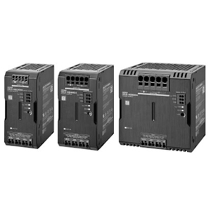
Our shared Value Design for Panel concept for the specifi cations of products used in control panels will create new value to our customer's control panels.
Combining multiple products that share the Value Design concept will further increase the value provided to control panels.
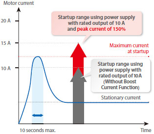
Motor-driven devices such as electric cylinders carry maximal instantaneous current when they start.
When the maximum current exceeds the rated current of a power supply without Boost Current Function, overload protection is activated to limit the output current. To avoid this, you must select a power supply with a rated output larger than the maximum current.
For example, if the maximum current exceeds 10 A, as in the figure on the below, you need a power supply with a rated output of 20 A.
S8VK-WA is equipped with a Boost Current Function that allows a peak current (150% of rated output) to flow for 10 seconds, which ensures a stable startup by a power supply with a rated output current of 10 A as described in the figure on the below.
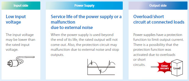
The equipment stopped and no output from the power supply.
Disconnecting cables and inspection with a tester is required to identify the cause, taking time and work.
�The cause is not clear.
�The failure cannot be reproduced.
�The problem recurs even after the power supply is replaced.
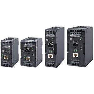
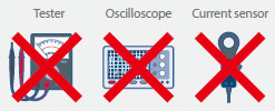
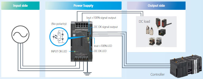
S8VK-WA shows you the source of the problem (e.g. input/output side of the Power Supply, or the main body),
without disconnecting cables or using a tester.
When the door of the control panel is closed, you can still check the status of the Power Supply via your controller, etc.,
using the signal that is output in synchronization with the LED
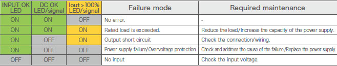
This feature clarifies the error status and necessary maintenance, minimizing the downtime.
| Power rating | 240 W | 480 W | 960 W | ||
|---|---|---|---|---|---|
| Item Output voltage | 24 V | 24 V | 24 V | ||
| Efficiency *1 |
Three-phase 200 VAC input |
93% typ. | 94% typ. | 95% typ. | |
|
Single-phase 200 VAC input |
92% typ. | 93% typ. | 94% typ. | ||
|
Three-phase 230 VAC input |
93% typ. | 94% typ. | 95% typ. | ||
|
Single-phase 230 VAC input |
93% typ. | 94% typ. | 95% typ. | ||
|
Input con- ditions |
Input voltage range *2 |
Three-phase/single-phase 170 to 264 VAC, 265 to 300 VAC (1 second) 240 to 350 VDC |
|||
| Frequency *2 | 50/60 Hz (47 to 63 Hz) | ||||
|
Input current *1 |
Three-phase 200 VAC input |
0.80 A typ. | 1.6 A typ. | 3.1 A typ. | |
|
Single-phase 200 VAC input |
1.4 A typ. | 2.6 A typ. | 5.2 A typ. | ||
|
Three-phase 230 VAC input |
0.70 A typ. | 1.4 A typ. | 2.7 A typ. | ||
|
Single-phase 230 VAC input |
1.2 A typ. | 2.3 A typ. | 4.5 A typ. | ||
| Power factor | 0.9 min. | ||||
|
Leakage current *3 |
Three-phase 200 VAC input |
1 mA max. | |||
|
Three-phase 230 VAC input |
1 mA max. | ||||
|
Inrush current *4 (for a cold start at 25�C) |
Three-phase 200 VAC input |
13 A typ. | 13 A typ. | 14 A typ. | |
|
Three-phase 230 VAC input |
15 A typ. | 15 A typ. | 16 A typ. | ||
|
Output character- istics |
Rated output current | 10 A | 20 A | 40 A | |
| Power Boost Function | 15 A | 30 A | 60 A | ||
| Voltage adjustment range *5 | 24 to 29.5 V (with V.ADJ) | 24 to 28 V (with V.ADJ) | |||
|
Ripple noise voltage *6 |
Three-phase 200 to 240 VAC input |
50 mVp-p max. at 20 MHz of bandwidth |
120 mVp-p max. at 20 MHz of bandwidth |
60 mVp-p max. at 20 MHz of bandwidth |
|
| Input variation influence *7 | 0.5% max. | ||||
| Load variation influence *8 | 1.5% max. | ||||
|
Temperature variation influence |
200 to 240 VAC input |
0.05%/�C max. | |||
|
Startup time *9 |
Three-phase 200 VAC input |
1,000 ms max. | |||
|
Three-phase 230 VAC input |
1,000 ms max. | ||||
|
Output hold time *9 |
Three-phase 200 VAC input |
35 ms typ. | 30 ms typ. | 25 ms typ. | |
|
Three-phase 230 VAC input |
35 ms typ. | 30 ms typ. | 25 ms typ. | ||
|
Additional functions |
Overload protection |
Yes, automatic reset, intermittent operation type Refer to Overload Protection below. |
|||
| Overvoltage protection |
Yes, 130% or higher of rated output voltage, power shut off (shut off the input voltage and turn on the input again), Refer to Overvoltage Protection below. |
||||
| Series operation | Yes (For up to two Power Supplies; external diodes required.) | ||||
| Parallel operation |
Yes (For up to two Power Supplies), Refer to Parallel Operation on Data sheet. |
||||
| INPUT OK Indicator | Yes (LED: Green) | ||||
| DC OK Indicator | Yes (LED: Green) | ||||
| Iout > 100% Indicator | Yes (LED: Yellow) | ||||
| DC OK Signal Output | Yes (MOS FET relay output 30 VDC max., 50 mA max.) | ||||
| Iout > 100% signal output | Yes (MOS FET relay output 30 VDC max., 50 mA max.) | ||||
| Insulation | Withstand voltage |
3.0 kVAC for 1 min. (between all input terminals and all output terminals, signal output terminals), cutoff current 20 mA |
|||
|
2.0 kVAC for 1 min. (between all input terminals and PE terminals), cutoff current 20 mA |
|||||
|
1.0 kVAC for 1 min. (between all output terminals, signal output terminals and PE terminals), cutoff current 25 mA |
|||||
|
0.5 kVAC for 1 min. (between all output terminals and all signal output terminals), cutoff current 10 mA |
|||||
| Insulation resistance |
100 MO min. (between all output terminals, signal output terminals and all input terminals / PE terminals) at 500 VDC |
||||
|
Environ- ment |
Ambient operating temperature *10 |
-40 to 70�C (Derating is required according to the temperature. Refer to Engineering Data on Data sheet.) (with no condensation or icing) |
|||
| Storage temperature | -40 to 85�C (with no condensation or icing) | ||||
| Ambient operating humidity | 95% max. (Storage humidity: 95% max.) | ||||
| Vibration resistance |
10 to 55 Hz, maximum 5 G, 0.42 mm single amplitude for 2 h each in X, Y, and Z directions |
||||
| Shock resistance | 294 m/s2, 3 times each in �X, �Y, �Z directions | ||||
| Reliability | MTBF *11 | 290,000 hrs typ. | 230,000 hrs typ. | 170,000 hrs typ | |
| Expected life *12 | 10 years min. | ||||
|
Construc- tion |
Weight | 800 g max. | 1,050 g max. | 1,750 g max. | |
| Cooling fan | No | ||||
| Degree of protection | IP20 by EN/IEC 60529 | ||||
| Standards | Harmonic current emissions |
Conforms to EN 61000-3-2 (single-phase *13) Complies with JIS C 61000-3-2 (three-phase, single-phase) |
|||
| EMI |
Conducted emissions |
Conforms to EN 61204-3 Class B, EN 55011 Class B (three-phase) Conforms to EN 61204-3 Class A, EN 55011 Class A (single-phase) |
Conforms to EN 61204-3 Class B, EN 55011 Class B (three-phase) Conforms to EN 61204-3 Class B, EN 55011 Class B (single-phase *14) Conforms to EN 61204-3 Class A, EN 55011 Class A (single-phase) |
||
|
Radiated emissions |
|||||
| EMS | Conforms to EN 61204-3 high severity levels | ||||
| Safety standards |
UL 508, UL121201 (Listing) CSA C22.2 No.107.1, CSA C22.2 No.213 (cUL) UL 62368-1 (Recognition) OVC II (= 3000 m) Pol2 CSA C22.2 No.62368-1 (cUR) OVC II (= 3000 m) Pol2 EN 62477-1 OVC III (= 2000 m) OVC II (2000 m < and = 3000 m) Pol2 EN 50178 OVC III (= 2000 m) OVC II (2000 m < and = 3000 m) Pol2 EN 62368-1 OVC II (= 3000 m) Pol2 EAC (TR CU 004 / 2011, TR CU 020 / 2011) RCM (EN61000-6-4) Complies with PELV (EN/IEC 60204-1) Complies with EN/IEC 61558-2-16 |
||||
| SEMI | Complies with SEMI F47-0706 (three-phase / single-phase 200 to 240 VAC input) | ||||
� To comply with PELV output requirements for EN/IEC 60204-1, ground the negative side of the output (-V) to a protective earth (PE).
� EN/IEC 61558-2-16
The S8VK-WA was designed based on EN/IEC 61558-2-16.
Currently, IEC 61558-2-17 has been replaced by IEC 61558-2-16.
When certification was received for EN/IEC 60204-1 (Machinery Safety), it was necessary to go through a control transformer to the control circuits. However, a control transformer is not always necessary for product that have been certified for the safety standard for OVCIII or for product that use a transformer that complies with EN/IEC 61558-2-16.
� Safety Standards for a DC Input
The following safety standards apply to a DC input: UL 62368-1, cUR (CSA C22.2 No. 62368-1), EN/IEC 62368-1, EN 50178, EN/IEC62477-1, EN/IEC 61558-2-16. Safety standard compliance is achievable by connecting a UL-certified fuse as specified below to the (L1/+) side.
For a DC power input, connect (L1/+) side to (+), and (L3/-) side to (-).
To select a UL certified fuse, refer to Recommended circuit breakers and fuses on Data Sheet.
The product is automatically protected from short-circuit current and overcurrent damages when the load current is in the range of 151 to 175% of the rated current.
When the output current falls within the rated range, the overload protection function is automatically cleared.
Overvoltage will be detected to prevent the load from being subjected to excessive voltage when the feedback circuit in the Power Supply fails, etc.
When an excessive voltage that is approximately 130% of the rated output voltage or more is output, the output voltage is cut OFF, preventing damage to the load due to overvoltage.
Reset the input power by turning it OFF for at least three minutes and then turning it back ON again.
Note: Do not turn ON the power again until the cause of the overvoltage has been removed.
Error locations at the input, product, and load side can be identified by the INPUT OK, DC OK, Iout > 100% Indicator / Signal Output.
(Unit: mm)
Note: The front mounting bracket can be used for front, side-by-side mounting as well.
PFP-100N
PFP-50N
PFP-M