Automation Systems
  Motion & Power Solutions
  Safety, Vision and IDENT
  Sensing Solutions
  Control Components
  Switching & Accessories
  Switchgear and Trolley Systems
  Process Weighing
  LED Lighting
  Omron
Omron
 Mitsubishi
 Delta
Delta
 Autonics
 Inno
Inno
 Panasonic
 Novotechnik
 Orientalmotor
 Microscan
 IPA
IPA
 Technomech
 Intech
 Honeywell
 IOT & Traceability
 Project & Panel Engg.
 Application Case Studies
 Solutions by Industry
 Solutions by Process
 Solutions by Product
 Youtube Videos
 Corporate Information
 Company Profile
 Quality Policy
 Mission Statement
 Chairman's Message
 Intech Group Companies

Compact Industrial SCARA
Compact Industrial Robot with light weight space saving arm. Its high speed operation is best suited for pick and place, labelling, tracking

Downtime can be reduced.
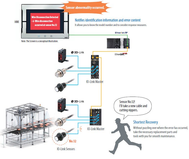
Notifies you of faulty parts and such phenomena in the sensor in real time.
The frequency of sudden failure can be decreased.
Condition monitoring of sensors and equipment to prevent troubles.
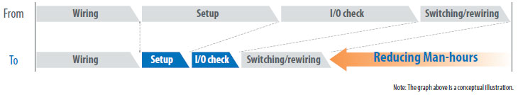
The efficiency of changeover can be improved.
The batch check for individual sensor IDs significantly decreases commissioning time.
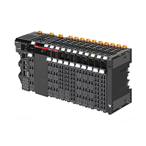
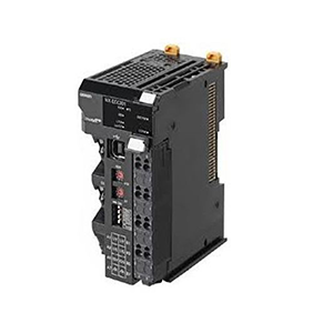
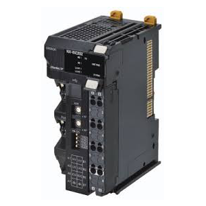
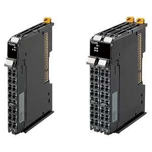
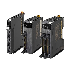
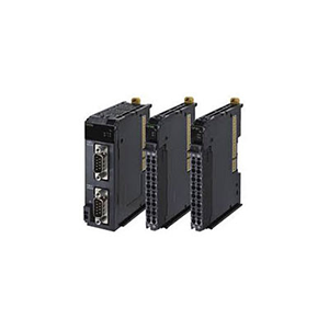
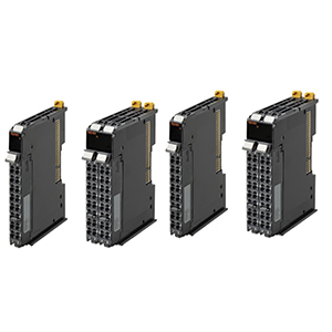
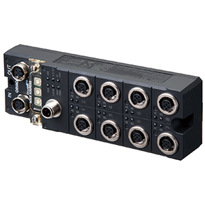
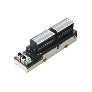
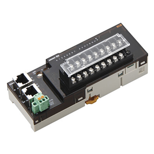
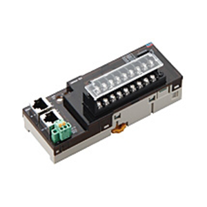
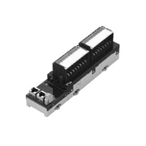
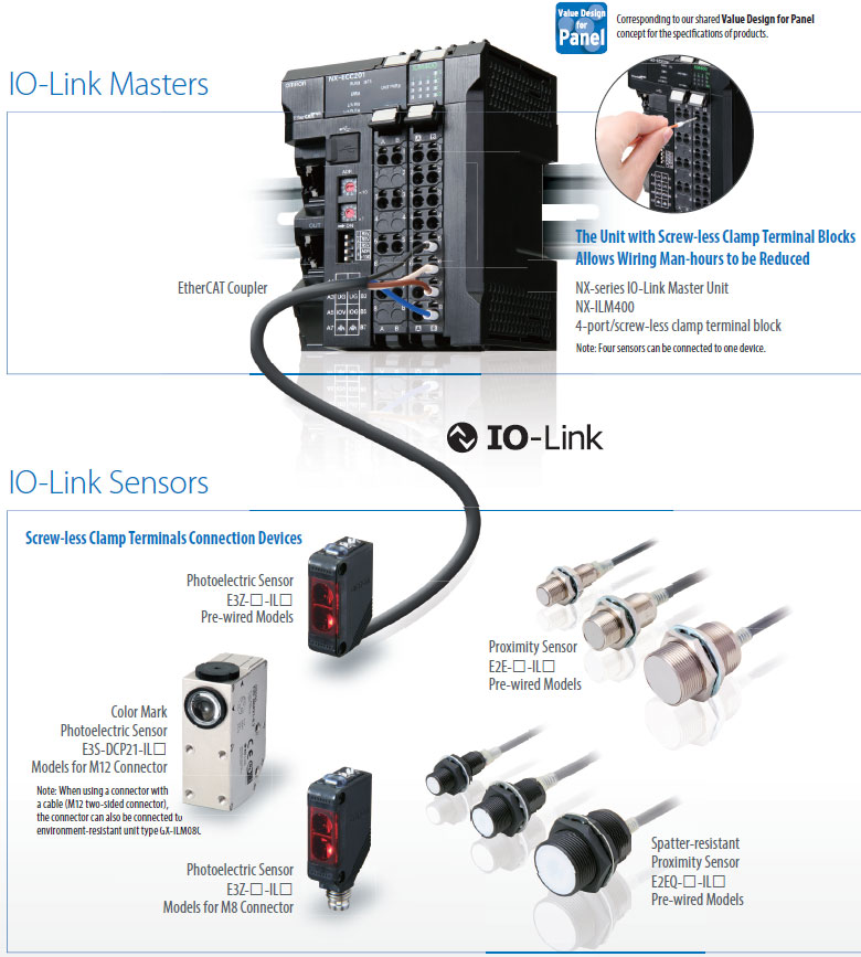
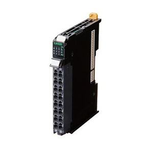
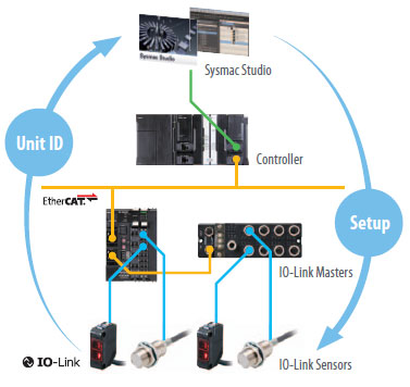
Omron provides two types of masters, a master unit with screw-less clamp terminal blocks and a master unit for M12 Smart click connectors, as IO-Link compliant devices and Sensors for connecting to the screw-less clamp terminals or to the M12 connector terminals that support each Master.

• An abnormality was displayed on the abnormality display screen, but upon going to look at the equipment, no external error was detected and the cause of the stop was not understood...
• Those responsible for maintenance investigated the cause of the abnormality from the activity of the stopped equipment, but because the maintenance person relied on the skill he or she has to identify the abnormality and replace the failed sensor, stoppages from 2 hours to several days occur...

When an abnormality occurs in a sensor, because you can see where the abnormality occurred and the factors estimated for it, you can go to where the abnormality occurred and recover the equipment in the shortest amount of time. Also with wire disconnection detection, not only output wires, but also power lines can be detected unconditionally.
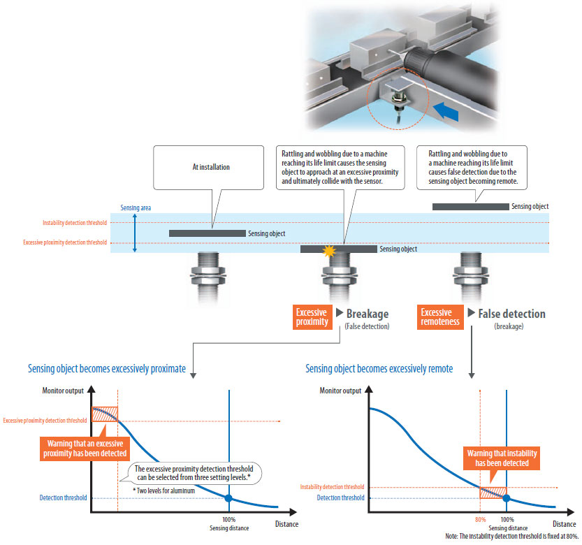
The detection position changes due to wear and vibration in the device’s mechanical parts and as a result, false detection and collision with the sensor have a negative impact on the device...
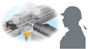
Constantly monitoring the position of the sensing object and notifying of excessive remoteness or proximity can be used for predictive maintenance of the device.

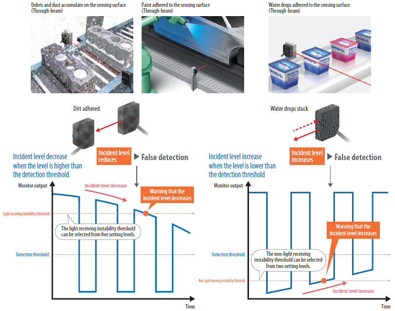
• In a conveyance process operating for 24 hours, dust or dirt accumulated on the detection surface of the photoelectric sensor, leading to a decline in the light incident level that causes the sensor to make false detection and the device to stop...
• Water drops stick to the sensing surface of the reflective sensor causing reflected light to enter...
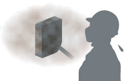
With a response time of 1 ms, photoelectric sensor’s light incident level is output for monitoring. It is output when the light incident level exceeds the instability detection threshold, so you can check the site before false detection occurs and perform predictive maintenance.

• During system start-up or changeover, operators had to perform the I/O check for each of the thousands of sensors installed on the line, and it took an enormous amount of time...
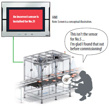
• When a sensor is installed wrong or an error occurs, wasteful work occurred that would normally be unnecessary...
By checking the sensor identification (manufacturer/sensor type/model number), you can easily check mistakes such as misconnected or unconnected sensors and installation mistakes. Also, because it is possible to program multiple sensors at once using the command language used only for the controller, it is also possible to reduce commissioning time sharply.
Program all at once to reduce commissioning time and inconsistent settings
Makes it possible to check for sensor installation mistakes before commissioning
Sysmac is a trademark or registered trademark of OMRON Corporation in Japan and other countries for OMRON factory automation products.
EtherCAT® is a registered trademark of Beckhoff Automation GmbH for their patented technology.
EtherNet/IPTM is the trademarks of ODVA.
Other company names and product names in this document are the trademarks or registered trademarks of their respective companies.
| Item | Specification | |
|---|---|---|
| Enclosure | Must be built into a panel. | |
| Grounding methods | Ground to 100 Ω or less. | |
|
Operating environment |
Ambient operating temperature |
0 to 55°C |
|
Ambient operating humidity |
10% to 95% (with no condensation or icing) | |
| Atmosphere | Must be free from corrosive gases. | |
|
Ambient storage temperature |
-25 to 70°C (with no condensation or icing) | |
| Altitude | 2,000 m max. | |
| Pollution degree | Pollution degree 2 or less: Conforms to JIS B3502 and IEC 61131-2. | |
| Noise immunity | Conforms to IEC 61000-4-4, 2 kV (power line). | |
|
Overvoltage category |
Category: Conforms to JIS B3502 and IEC 61131-2. | |
| EMC immunity level | Zone B | |
| Vibration resistance |
Conforms to IEC 60068-2-6. 5 to 8.4 Hz with amplitude of 3.5 mm, 8.4 to 150 Hz, acceleration of 9.8 m/s2 100 min each in X, Y, and Z directions (10 sweeps of 10 min each = 100 min total) |
|
| Shock resistance | Conforms to IEC 60068-2-27. 147 m/s2, 3 times each in X, Y, and Z directions | |
| Applicable standards * |
UL 61010-2-201, ANSI/ISA 12.12.01, EU: EN 61131-2, RCM, KC, and IO-Link conformance |
|
* Ask your OMRON representative for the most recent applicable standards for each model.
| Item | Specification | |
|---|---|---|
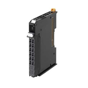
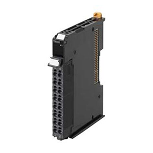
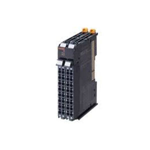
| Unit name | IO-Link Master Unit | |
| Model | NX-ILM400 | |
| Number of ports | 4 | |
|
Communications specifications |
Communications protocol | IO-Link protocol |
| Baud rate |
COM1: 4.8kbps COM2: 38.4kbps COM3: 230.4kbps |
|
| Topology | 1:1 | |
| Compliant standards |
• IO-Link interface and system specification version1.1.2 • IO-Link test specification version1.1.2 |
|
|
Power supply to devices* in IO-Link Mode or SIO (DI) Mode |
Rated voltage | 24 VDC (20.4 to 28.8 VDC) |
| Maximum load current | 0.2 A/port | |
| Short-circuit protection | Provided. | |
|
Digital inputs (in SIO (DI) Mode) |
Internal I/O common | PNP |
| Rated voltage | 24 VDC (20.4 to 28.8 VDC) | |
| Input current | 5 mA typical (24 VDC) | |
| ON voltage/ON current | 15 VDC min., 2 mA min. | |
| OFF voltage | 5 VDC max. | |
| Input filter time |
No filter, 0.25 ms, 0.5 ms, 1 ms (default), 2 ms, 4 ms, 8 ms, 16 ms, 32 ms, 64 ms,128 ms, 256 ms |
|
|
Digital outputs (in SIO (DO) Mode) |
Internal I/O common | PNP |
| Output type | Push-pull | |
| Rated voltage | 24 VDC (20.4 to 28.8 VDC) | |
| Maximum load current | 0.1 A/port | |
| Short-circuit protection | Provided. | |
| Leakage current | 0.1 mA max. | |
| Residual voltage | 1.5 V max. | |
|
Digital inputs for pin 2 (in IO-Link Mode) |
Internal I/O common | PNP |
| Rated voltage | 24 VDC (20.4 to 28.8 VDC) | |
| Input current | 2 mA typical (24 VDC) | |
| ON voltage/ON current | 15 VDC min., 2 mA min. | |
| OFF voltage | 5 VDC max. | |
| Input filter time |
No filter, 0.25 ms, 0.5 ms, 1 ms (default), 2 ms, 4 ms, 8 ms, 16 ms, 32 ms, 64 ms, 128ms, 256 ms |
|
|
Cable specifications |
Cable type | Unshielded |
| Length | 20 m max. | |
|
Electrostatic capacity between lines |
3 nF max. | |
| Loop resistance | 6 Ω max. | |
| External connection terminals | Screwless clamping terminal block (16 terminals) | |
| I/O refreshing method | Free-Run refreshing | |
| Dimensions | 12 × 100 × 71 mm (W × H × D) | |
| Isolation method | Photocoupler isolation | |
| Insulation resistance | 20 MΩ min. at 100 VDC (between isolated circuits) | |
| Dielectric strength |
510 VAC for 1 min, leakage current: 5 mA max. (between isolated circuits) |
|
| I/O power supply method | Supply from the NX bus | |
| NX Unit power consumption |
• Connected to a CPU unit 1.05 W max. • Connected to a Communications Coupler Unit 0.80 W max. |
|
| Current consumption from I/O power supply | 50 mA | |
| Weight | 67 g | |
| Circuit configuration |

|
|
| Terminal connection diagram |

|
|
| Installation orientation and restrictions |

|
|
| Protective functions |
L+ terminal short-circuit protection C/Q terminal short-circuit protection |
|
| Function | Description | |
|---|---|---|
| Communications |
Cyclic communications |
I/O data (process data) in the IO-Link devices is cyclically exchanged with the IO-Link Master Unit as the IO-Link communications master. At the same time, this data and the status of the IO-Link Master Unit is cyclically exchanged with the controller, with the IO-Link Master Unit operating as a slave of the controller. Cyclic communications can be used to check the amount of detection performance deterioration in devices, and to check changes in usage conditions, such as the amount of incident light for photoelectric sensors, stability detection margins, and excessive proximity for proximity sensors. |
|
Message communications |
The controller can send messages (commands) to the IO-Link Master Unit and receive the response from the IO-Link Master Unit. The IO-Link Master Unit can also function as a gateway to send messages (commands and responses) between the controller and the IO-Link devices. During operation, you can change and adjust device parameters, such as threshold settings, tuning execution, and ON-delay time changes, from a program. Or, during operation, you can check the internal status, such as the operating times of devices. |
|
| Communications mode settings |
You can select any of the following modes for each port: IO-Link Mode, SIO (DI) Mode, SIO (DO) Mode, and Disable Port This allows you to combine IO-Link communications and digital I/O in a single unit. |
|
| Digital inputs for pin 2 | In IO-Link Mode, you can perform digital input with pin 2 while performing IO-Link communications. | |
|
Automatic baud rate setting for IO-Link communications |
The IO-Link Master Unit automatically matches the specific baud rates (COM1, COM2, or COM3) of the IO-Link devices to communicate with the IO-Link devices. Therefore, it is not necessary to set the baud rate of the connected device for each port. |
|
| Connected device verification |
This function is used to verify the configuration of IO-Link devices that are connected to the IO-Link Master Unit against the registered IO-Link device configuration settings when the power supply is turned ON. The user can enable or disable connected device verification. |
|
|
IO-Link communications error detection |
This function detects I/O cable breaks, disconnections from IO-Link device ports, error-level device events, device configuration verification errors, and IO-Link device malfunctions. | |
|
Detection of short-circuits in I/O cables |
This function detects short-circuits in I/O cables | |
| Notification of input data validity | The controller can use the Input Data Enabled Flags to determine whether the process input data for IO-Link communications is valid. | |
|
Load rejection for controller communications error |
This function turns OFF outputs from the IO-Link Master Unit when a communications error occurs in communications with the controller in IO-Link Mode or in an SIO mode. This prevents incorrect output operations when communications error occurs. |
|
|
IO-Link total communications lost frames |
The IO-Link total communications lost frames can be read from the CX-ConfiguratorFDT. You can use this function to determine communications status as affected by I/O cable noise or other factors. |
|
| Digital input filter | This function is used to eliminate chattering and noise of the input signal for digital inputs in SIO(DI) Mode or for digital inputs for pin 2 in IO-Link Mode. It prevents data change and stabilizes the input signal even in situations where the input data changes due to chattering or noise and the bit status is unstable. | |
| Digital input collection* |
In IO-Link Mode, this function reflects the specified bit data in the input data from the IO-Link device on the digital input data of the IO-Link Master Unit. As a result, the bit data in the input data from the IO-Link device can be aggregated into the digital input data of the IO-Link Master Unit. One bit for each IO-Link port can be aggregated. This function cannot be used in SIO (DI) Mode and SIO (DO) Mode. If you use this function, digital inputs with pin 2 cannot be used. |
|
|
Backup and restoration of parameter settings in IO-Link devices |
This function is used to back up parameter settings in IO-Link devices in the IO-Link Master Unit or restore them to IO-Link devices. This eliminates the need to set parameters again after replacing an IO-Link device. |
|
| Event log |
This function records events, such as errors and status changes, that occur in the IO-Link Master Unit and the IO-Link devices. This enables partial troubleshooting for NJ/NX-series Controllers and NY-series Industrial PCs. |
|
* This function is supported with the unit version 1.1 or later.
Refer to the user's manual for the CPU Unit for the CPU Unit to which NX Units can be connected
| NX Unit | Corresponding versions * | |||
|---|---|---|---|---|
| Model | Unit version | CPU Unit | Sysmac Studio | CX-ConfiguratorFDT |
| NX-ILM400 | Ver.1.1 | Ver1.13 or later | Ver1.20 or higher | Ver2.3 or higher |
| Ver.1.0 | Ver.1.13 or later | Ver.1.17 or higher | Ver.2.3 or higher | |
* Some units do not have all of the versions given in the above table. If a unit does not have the specified version, support is provided by the oldest available version after the specified version. Refer to the user’s manuals for the specific units for the relation between models and versions.
| NX Unit | Corresponding versions * | |||||||
|---|---|---|---|---|---|---|---|---|
| Model |
Unit version |
EtherCAT | EtherNet/IP | |||||
|
Communi- cations Coupler Unit |
NJ/NX- series CPU Units or NY-series Industrial PCs |
Sysmac Studio |
CX- Configurator FDT |
Communi- cations Coupler Unit |
Sysmac Studio |
CX- Configurator FDT |
||
| NX-ILM400 | Ver.1.1 |
Ver.1.0 or later |
Ver.1.12 or later |
Ver.1.20 or higher |
Ver.2.2 or higher |
Ver.1.0 or later |
Ver.1.20 or higher |
Ver.2.2 or higher |
| Ver.1.0 |
Ver.1.0 or later |
Ver.1.12 or later |
Ver.1.16 or higher |
Ver.2.2 or higher |
Ver.1.0 or later |
Ver.1.16 or higher |
Ver.2.2 or higher |
|
* Some units do not have all of the versions given in the above table. If a unit does not have the specified version, support is provided by the oldest available version after the specified version. Refer to the user’s manuals for the specific units for the relation between models and versions.
(Unit: mm)
NX-ILM400
12 mm Width