Automation Systems
  Motion & Power Solutions
  Safety, Vision and IDENT
  Sensing Solutions
  Control Components
  Switching & Accessories
  Switchgear and Trolley Systems
  Process Weighing
  LED Lighting
  Omron
Omron
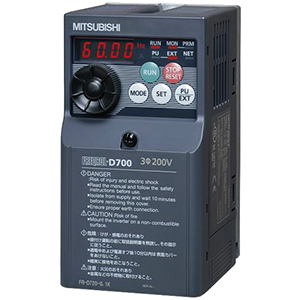
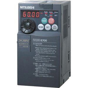
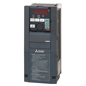
 Mitsubishi
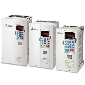
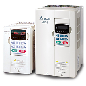
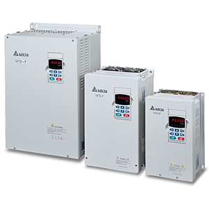
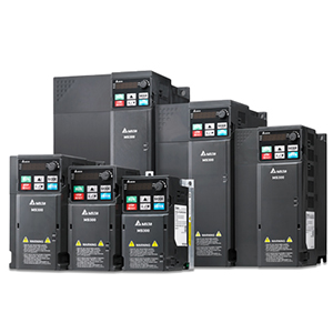
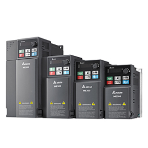
 Delta
Delta
 Autonics
 Inno
Inno
 Panasonic
 Novotechnik
 Orientalmotor
 Microscan
 IPA
IPA
 Technomech
 Intech
 Honeywell
 IOT & Traceability
 Project & Panel Engg.
 Application Case Studies
 Solutions by Industry
 Solutions by Process
 Solutions by Product
 Youtube Videos
 Corporate Information
 Company Profile
 Quality Policy
 Mission Statement
 Chairman's Message
 Intech Group Companies

Compact Industrial SCARA
Compact Industrial Robot with light weight space saving arm. Its high speed operation is best suited for pick and place, labelling, tracking

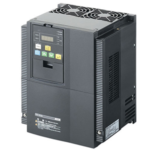
High starting torque and torque control capability in open loop mode give you full control of your machine dynamics and performance. Options for all of the major open network systems.
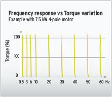
The MX2-V1 delivers 200% starting torque near stand-still (0.5 Hz) and can operate in torque control in open loop mode. This allows the MX2-V1 to be used in applications where closed loop AC vector drives were previously used.
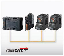
Standard industrial networks, such as EtherCAT, CompoNet or DeviceNet as options. High-speed EtherCAT provides solutions for the entire system from input to output with Sysmac Series.
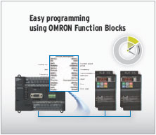
Built-in RS-485 Modbus communications. OMRON Function Blocks are available for the CP H/L and CJ-series PLCs. Those control the MX2-V1 via Modbus communications easily.
Safety is embedded in the MX2-V1, according to ISO 13849-1, Cat. 3, with two safety inputs and an External Device Monitoring (EDM) output.
No external contactors on the motor side are required, meaning simpler wiring for the user.
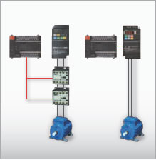
Dual contactors at the output of the inverter are no longer required.
Direct connection to a safety controller ensures compliance to ISO 13849-1, Cat. 3.
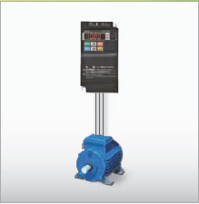
The PM motor conforming to high-efficiency regulations can be controlled. The PM motor promotes further energy saving and achieves earth-friendly machine control.
The MX2-V1 is a drive and position controller in one, ideal for modular machines where moderate positional accuracy is required. Speed synchronisation is also possible, with no additional programming required.
With no external hardware required, and via standard parameter settings, speed synchronisation can be achieved. The MX2-V1 will act as a speed follower to an external pulse generator/encoder signal up to 32 KHz.
Specially developed application functionality enables the MX2-V1 to solve simple positioning tasks without the need for an external controller. Up to 8 positions, plus home, can be selected by the user, and furthermore, the MX2-V1 can be switched between speed and position mode.
The MX2-V1 gives you the power to create smart solutions using PLC functionality, as standard. Via an intuitive flow chart programming tool, you can create programs with up to 1000 lines of code and with 5 tasks running in parallel.

(Unit: mm)
3G3MX2-AB001-V1
3G3MX2-AB002-V1
3G3MX2-AB004-V1
3G3MX2-A2001-V1
3G3MX2-A2002-V1
3G3MX2-A2004-V1
3G3MX2-A2007-V1
3G3MX2-AB007-V1
3G3MX2-AB015-V1
3G3MX2-AB022-V1
3G3MX2-A2015-V1
3G3MX2-A2022-V1
3G3MX2-A4004-V1
3G3MX2-A4007-V1
3G3MX2-A4015-V1
3G3MX2-A4022-V1
3G3MX2-A4030-V1
3G3MX2-A2037-V1
3G3MX2-A4040-V1
3G3MX2-A2055-V1
3G3MX2-A2075-V1
3G3MX2-A4055-V1
3G3MX2-A4075-V1
3G3MX2-A2110-V1
3G3MX2-A4110-V1
3G3MX2-A4150-V1
3G3MX2-A2150-V1
3G3AX-NFI21
3G3AX-NFI22
3G3AX-NFI25/3G3AX-NFI26
3G3AX-NFI45/3G3AX-NFI46
3G3AX-NFI23/3G3AX-NFI24
3G3AX-NFI41/3G3AX-NFI42
3G3AX-NFI43/3G3AX-NFI44
3G3AX-NFO01
3G3AX-NFO02
3G3AX-NFO03/3G3AX-NFO04/3G3AX-NFO05
3G3AX-NFO06
3G3AX-AL2025
3G3AX-AL2055
3G3AX-AL2110/3G3AX-AL2220
3G3AX-AL2330
3G3AX-AL4025/3G3AX-AL4055
3G3AX-AL4110
3G3AX-AL4220/3G3AX-AL4330