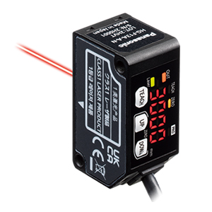
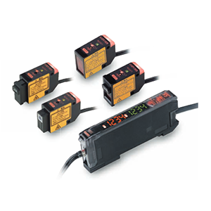
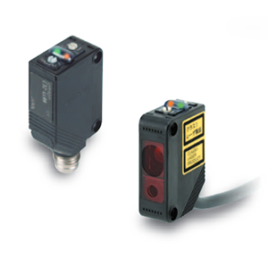
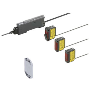
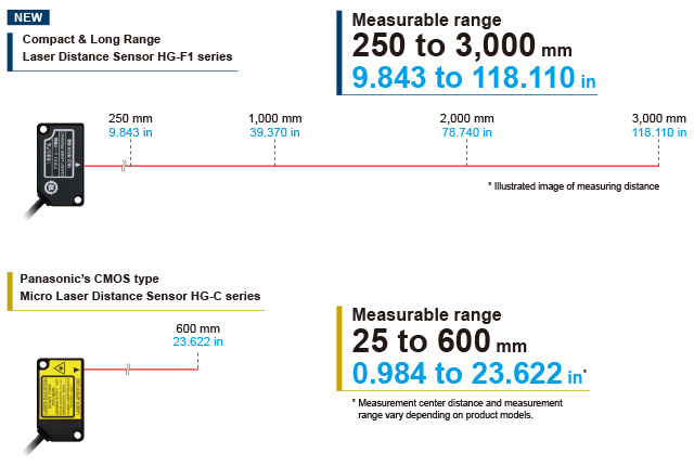
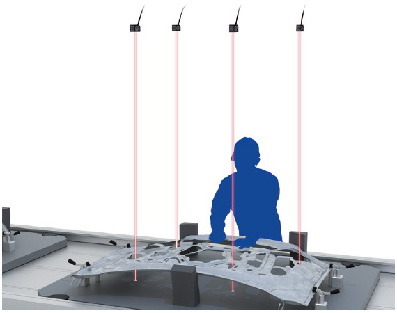
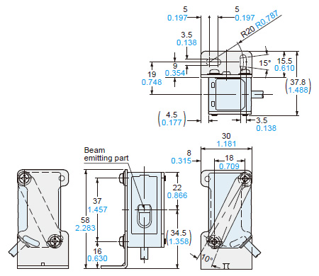
The laser distance sensor HG-F1 series features a lightweight and high-strength aluminum diecast case
with a built-in TOF sensor module.
The sensor unit boasts a compact and robust body and offers a long-range sensing capability.
|
|
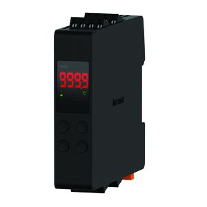
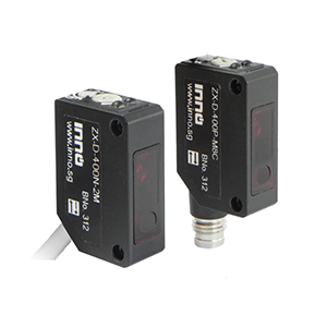
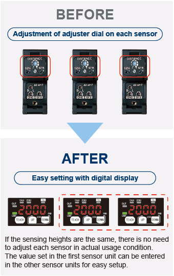
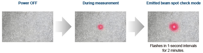
The sensor unit has a 7-segment display and enables the numerical setting of threshold
values in mm.
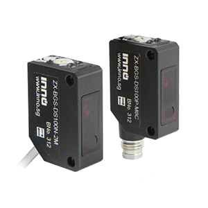
When multiple sensor units are used, the conventional adjuster setting method requires the adjustment of
each sensor in actual usage condition. With the HG-F1 series, the distance (numeric value) set in the
first sensor unit can be used as a guideline for setting the distance in the second and other sensor
units.
|
|
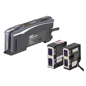
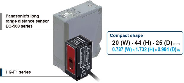
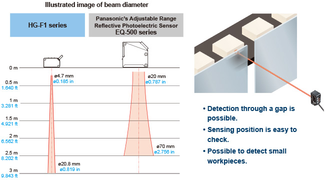
The HG-F1 series sensor has been downsized to about 80% of the previous long range distance
sensor model (EQ-500 series) by volume ratio.
The unit body is made of aluminum diecast so it is lightweight and robust.
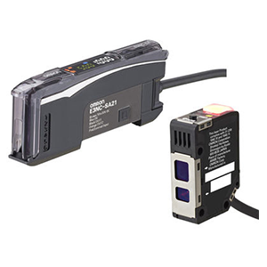
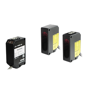
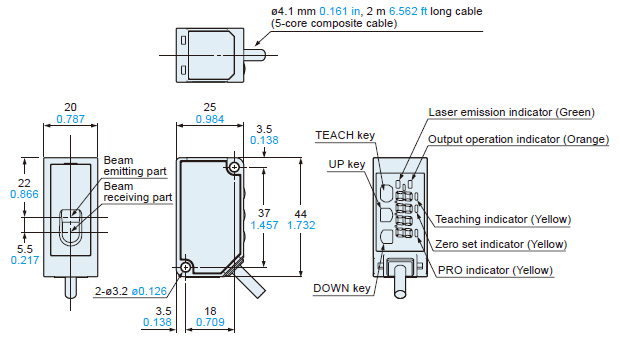
|
|
|
Type | NPN output type | PNP output type | ||
---|---|---|---|---|
Model No. | HG-F13A-A-N | HG-F13A-A-P | ||
Measurable range | 250 to 3,000 mm 9.843 in to 118.110 in | |||
Displayable range (Note 2) | 200 to 3,300 mm 7.874 in to 129.921 in | |||
Repeatability | 10 mm 0.394 in or less | |||
Hysteresis | 30 mm 1.181 in (default setting) Possible to vary up to 1 mm 0.039 in minimum in the PRO mode (Note 3) | |||
Linearity | ± 2% F.S. (Note 4) (at a measuring distance of 500 mm to 3,000 mm 19.685 in to 118.110 in) | |||
Temperature characteristics | 0.1% F.S./℃ | |||
Light source | Red semiconductor laser: Class 1 [JIS / IEC / GB / KS / FDA(Note 5)] Maximum output: 0.39 mW, Peak emission wavelength: 680 nm 0.0268 mil |
|||
Beam diameter (Note 6) | Approx. ø10 mm ø0.394 in (typical) (at the measuring distance of 1,000 mm 39.370 in) | |||
Supply voltage | 24 V DC ±10%, including 10% ripple (P-P) | |||
Power consumption (Note 7) | 40 mA or less (at 24 V DC supply voltage) | |||
Control output | NPN open-collector transistor • Maximum sink current: 50 mA • A pplied voltage: 30 V DC or less (Between control output to 0 V) • Residual voltage: 1.5 V or less (At 50 mA sink current) • Leakage current: 0.1 mA or less |
PNP open-collector transistor • Maximum source current: 50 mA • Applied voltage: 30 V DC or less (Between control output to +V) • Residual voltage: 1.5 V or less (At 50 mA source current) • Leakage current: 0.1 mA or less |
||
Output operation |
Switchable between Light-ON / Dark-ON, (Default: Light-ON) | |||
Short-circuit protection |
Incorporated (Auto reset type) | |||
Analog output | Switchable between voltage output / current output (Default: voltage output) | |||
Analog voltage output |
Output range(Note 9) | • In normal operation: 0 to +5 V Possible to set the distance range (Default: 250 to 3,000
mm 9.843 in to 118.110 in) • When alarm occurs: Last value is held or the range is set to 0 V on the near point side and to +5.2 V on the far point side. |
||
Output impedance |
100 Ω | |||
Analog current output |
Output range(Note 9) | • In normal operation: +4 mA to +20 mA Possible to set the distance range (Default: 250 to
3,000 mm 9.843 in to 118.110 in) • When alarm occurs: Last value is held or the range is set to 0 mA on the near point side and to +20.8 mA on the far point side. |
||
Output impedance |
250 Ω or less | |||
Response time | Switchable between 35 ms / 100 ms / 300 ms / 2,000 ms (Default: 100 ms) | |||
External input | NPN non-contact input • Input condition Invalid: +8 to + V DC or Open Valid: 0 to +1.2 V DC • Input impedance: approx. 10 kΩ |
PNP non-contact input • Input condition Invalid: 0 to +0.6 V DC or Open Valid: +4 to +V DC • Input impedance: approx. 10 kΩ |
||
External input function | Switchable between zero set, teaching, or emission stop (Default: zero set) | |||
Teaching function | Switchable between normal sensing mode (2-point / limit) or window comparator mode
(1-point / 2-point / 3-point) (Default: Normal sensing mode) |
|||
Timer function | Switchable between OFF / ON delay / OFF delay / one-shot (Default: OFF) | |||
Timer period | Switchable between 5 ms / 10 ms / 25 ms / 50 ms / 100 ms / 250 ms / 500 ms / 1,000 ms / 5,000 ms (Default: 5 ms) | |||
Pollution degree | 2 | |||
Overvoltage category | Category I | |||
Ambient altitude (Note 8) | 2,000 m 6561.680 ft or less | |||
Environmental resistance |
Protection | IP67 (IEC) | ||
Ambient temperature | -10 to +45 ℃ +14 to 113 ℉ (No dew condensation or icing allowed), Storage: -20 to +60 ℃ -4 to 140 ℉ | |||
Ambient humidity | 35 to 85% RH, Storage: 35 to 85% RH | |||
Ambient illuminance | Incandescent light: 3,000 ℓx or less at the light-receiving face | |||
Vibration resistance | 10 to 55 Hz (period: 1 min.) frequency, 1.5 mm 0.059 in double amplitude in X, Y and Z directions for two hours each | |||
Shock resistance | 500 m/s2 acceleration (approx. 50 G) in X, Y and Z directions three times each | |||
Cable | 0.2 mm2 5-core composite cable, 2 m 6.562 ft long | |||
Cable extension | Extension up to total 10 m 32.808 ft is possible with 0.3 mm2, or more, cable | |||
Material | Enclosure: Aluminum die-cast, Front cover: Acrylic, Cable: PVC | |||
Weight | Net weight: approx. 85 g, Gross weight: approx. 130 g |
Notes:
1) | Unless otherwise specified, measurement conditions are as follows: Power supply voltage of 24 VDC, ambient
temperature of +20 ℃ +68 ℉, response time of 100 ms, and measuring
distance of 1,000 mm 39.370 in. The target object is a 200 mm × 200 mm 7.874 in ×7.874 in white non-glossy paper. Perform measurement 30 minutes after turning on the power supply. |
---|---|
2) | When an object is detected, the range of numerical values that appear on the digital display is regarded as the displayable distance. When zero setting is performed, the displayable distance varies depending on the zero setting distance. |
3) | Changing the hysteresis may result in unstable sensing. After making a change, perform operation check using actual equipment. |
4) | F.S. (full scale) represents a range from 0 mm to 3,000 mm 0 in to 118.110 in. |
5) | This product complies with the FDA regulations (FDA 21 CFR 1040.10 and 1040.11) in accordance with FDA Laser Notice No. 56, except for complying with IEC 60825-1 Ed. 3. |
6) | The beam diameter is defined as 1/e2 (approx. 13.5%) of the center light intensity. Due to leak light outside the defined range, the measurement values may be affected if the reflectance around the detecting point is higher than that of the detecting point. |
7) | Analog output is not included. |
8) | Do not use or store this product in environments where ambient air is pressurized to an air pressure higher than the atmospheric pressure at an altitude of 0 m. |
9) | When the intensity of received light is unstable, the voltage is output as 0 V and the current is output as 0 mA. |
EU Regulations: | EMC Directive 2014/30/EU |
---|---|
UK Regulations: | EMC Regulations 2016/1091 |
● Applicable standards
USA regulations: | FDA21 CFR1040.10, and 1040.11 (Laser Notice No.56 applied) |
---|
● USA/Canada Standards
● Other standards
Sensor
|
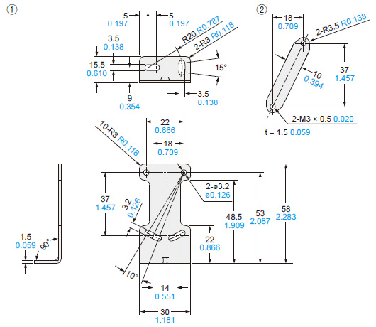
Simple mounting bracket (Optional)
|
|
TITLE | DOCUMENT TYPE | SIZE |
HG-F1 Series Catalog | Catalog | 3120 KB |
---|---|---|
HG-F1 Series User Manual | Manual | 4340 KB |