Automation Systems
  Motion & Power Solutions
  Safety, Vision and IDENT
  Sensing Solutions
  Control Components
  Switching & Accessories
  Switchgear and Trolley Systems
  Process Weighing
  LED Lighting
  Omron
Omron
 Mitsubishi
 Delta
Delta
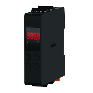
 Autonics
 Inno
Inno
 Panasonic
 Novotechnik
 Orientalmotor
 Microscan
 IPA
IPA
 Technomech
 Intech
 Honeywell
 IOT & Traceability
 Project & Panel Engg.
 Application Case Studies
 Solutions by Industry
 Solutions by Process
 Solutions by Product
 Youtube Videos
 Corporate Information
 Company Profile
 Quality Policy
 Mission Statement
 Chairman's Message
 Intech Group Companies

Compact Industrial SCARA
Compact Industrial Robot with light weight space saving arm. Its high speed operation is best suited for pick and place, labelling, tracking

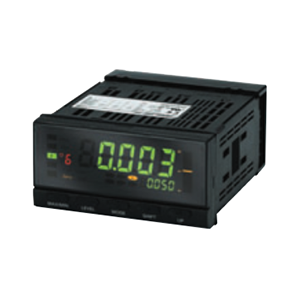
Note: No-voltage contacts of up to 30 Hz are supported.
*1 Visual confirmation of judgement results is not supported on models that do not have an output or models that do not
support DeviceNet.
You can change the display color by setting it, but you cannot switch it based on the judgement results.
*2 DeviceNet models have a depth of 97 mm.
last update: September 04, 2014
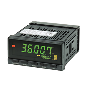
*1. DeviceNet models: 97 mm
*2. Leave a distance of at least 140 mm when using the Wate Cover Y92A-49N.
Note: Mounting Recommended Panel Thickness 1 to 8 mm.
Mount the product horizontally.
Terminal: M3, Terminal Cover: Accessory
last update: September 04, 2014