Frequently asked questions and answers for Digital Panel Indicators - Industrial Automation
What is the measuring accuracy when measuring circumferential speed with the K3NR Digital Panel Indicator?
The measuring accuracy for K3NR operating mode 1 (rotational/circumferential speed) is ±0.006% rdg ±1 digit. If the variation of input pulses is not considered, the error depends on the number of significant digits displayed below the decimal point. The error is the error in the read value.
Calculation: 85.000 km/h × (0.006%) = ±0.0051 km/h
In this case, three digits are displayed below the decimal point, so the fourth digit below the decimal point in ±0.0051 km/h is rounded off to yield an accuracy of ±0.005 km/h. There is also an error of ±1 added to the rightmost digit (±0.001 km/h) for a total error of ±0.005 km/h ±0.001 km/h = ±0.006 km/h. Consequently, the display may vary between 84.994 and 85.006 km/h.
Calculation: 85.000 km/h × (±0.006%) = ±0.0051 km/h
In this case, two digits are displayed below the decimal point, so the third digit below the decimal point in ±0.0051 km/h is rounded off to yield an accuracy of ±0.01 km/h. There is also an error of ±1 added to the rightmost digit (±0.01 km/h) for a total error of ±0.01 km/h ±0.01 km/h = ±0.02 km/h. Consequently, the display may vary between 84.98 and 85.02 km/h.
Calculation: 85.000 km/h × (±0.006%) = ±0.0051 km/h
In this case, one digit is displayed below the decimal point, so the second digit below the decimal point in ±0.0051 km/h is rounded off to yield an accuracy of ±0.0 km/h. There is also an error of ±1 added to the rightmost digit (±0.1 km/h) for a total error of ±0.0 km/h ±0.1 km/h = ±0.1 km/h. Consequently, the display may vary between 84.9 and 85.1 km/h
Can one sensor with a 4- to 20-mA output be connected to two K3NX or K3TS Digital Panel Indicators?
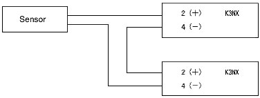
It is possible to connect two Meters. Connect the Meters in parallel, as shown in the following diagram.
Note:
The input resistance of the K3NX and K3TS is 10 Ω. When connecting two K3NX or K3TS Process Meters, the sensor's permissible load resistance must be 20 Ω or higher.
Calculating the Maximum Number of Connectable Meters:
Use the following equation to determine how many Meters can be connected.
Sensor's permissible load resistance > Digital Panel Meter's input resistance × Number of Meters
Can one sensor with a 4- to 20-mA output be connected to two K3NX or K3TS Digital Panel Indicators?
It is possible to connect two Meters. Connect the Meters in parallel, as shown in the following diagram.
Note:
The input resistance of the K3NX and K3TS is 10 Ω. When connecting two K3NX or K3TS Process Meters, the sensor's permissible load resistance must be 20 Ω or higher.
Calculating the Maximum Number of Connectable Meters:
Use the following equation to determine how many Meters can be connected.
Sensor's permissible load resistance > Digital Panel Meter's input resistance × Number of Meters
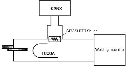
How can a DC current of 1,000 A be measured with a K3NX Digital Panel Indicator?
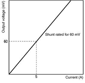
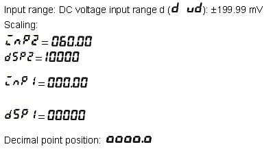
Use an SDV-SH1000 Shunt, read the converted DC voltage signal at the K3NX, and scale the read value for display on the K3NX
Note: OMRON has a wide range of Shunts available, with rated currents ranging from 5 A to 1,000 A.
Setting Examples:
Which parameter should be set in order to display the K3NR Digital Panel Indicator's rotation speed?
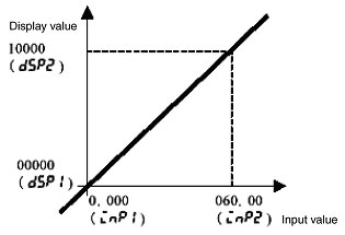
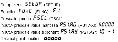
When you want to display the rotation speed on the K3NR, the rotation speed will be expressed as: Rotation speed (rpm) = Input frequency f (Hz) × 60 × α.
α = Prescale value
When displaying rpm with 2 pulses/rotation, make the following settings from the setup menu.
When 2 pulses are output/revolution, α = 1/N = 1/2 = 0.5 = 5.0000 × 10⁻¹ m:
Reference: Calculating the Prescale Values
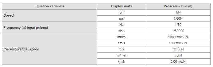
N: Number of pulses per rotation
πd: Circumference (units: m)
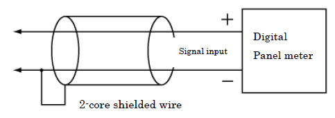
There is no response to commands sent from the host computer to the Meter via serial communications. What should I do?
Items to Check
1.Refer to the following diagrams and check the wiring.
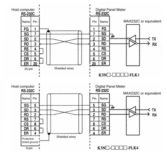
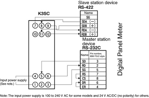
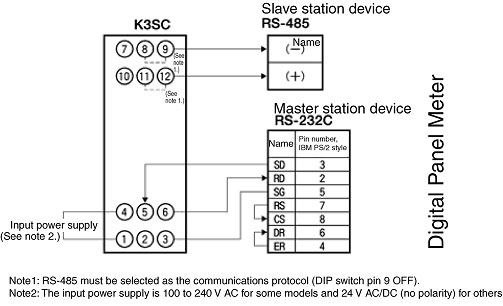
2.Verify that the commands are being sent in ASCII, according to the communications format. Refer to the following diagrams for details.
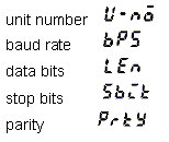
3.Verify that the unit number, baud rate, data bits, stop bits, and parity settings are the same in the host computer and Digital Panel Meter.
For details, refer to the following figures.
Note:
If an "H" is added after a number, like (02H) below, the number is expressed in hexadecimal. If the number is shown as a character string in double quotation marks, like "00" below, the number is expressed in ASCII characters.
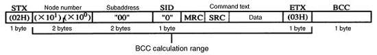
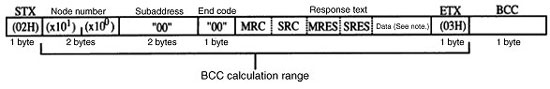
Note:There will be no data if a command frame error occurs (end code other than "00" or "0F").
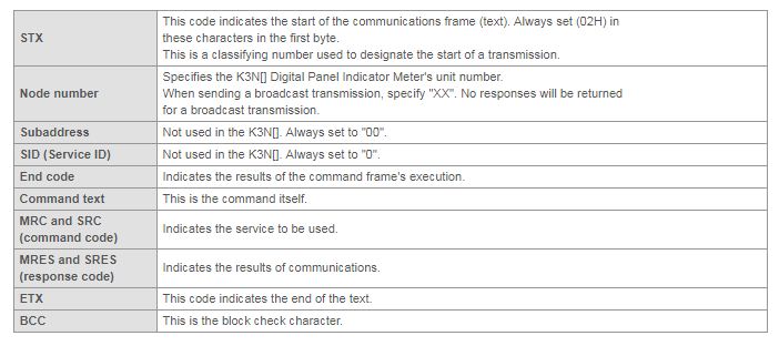
The BCC result is found by calculating the exclusive OR of the bytes from the node number through ETX.
BCC calculation method: The BCC is the result of an exclusive OR of all bytes from just after STX through ETX.
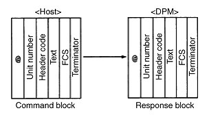
In the Digital Panel Meter Series, Host Link communications are the conversational type of communications protocol conforming to the PC's host link protocol. The host computer has the transmission right first, and initiates the communications. The transmission right is transferred with each block that is sent. When a command block is sent, a response block is always returned.
Note:
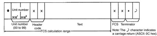
1.The unit number is equivalent to the unit number in the Programmable Controller.
2.When two or more devices are connected, do not duplicate the unit numbers.
The blocks sent from the host computer are called command blocks.
The blocks sent from the Digital Panel Meter are called response blocks.
A block begins with the start character (@) and communications address, and ends with the FCS code and terminator.
The sensor is operating normally, but the K3NR Digital Panel Indicator's display is not changing. Why is this happening?
The following three causes are most likely.
Note:The FM output from a Mitsubishi inverter is a voltage pulse output.
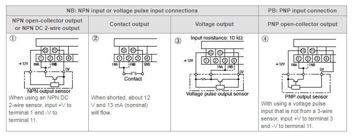
Check the sensor's leakage current. When connecting to a K3NR, select a sensor with an OFF leakage current of 1.5 mA max.It is especially important to have an appropriate leakage current when using a 2-wire sensor or Solid-state Relay.
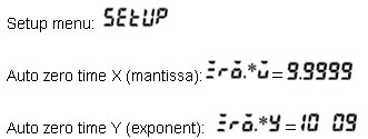
The K3NR calculates the predicted pulse interval in order to predict when the next pulse will be input. If a pulse input is not received within a certain time, it is necessary to indicate that rotation has stopped (set display value to 0), and the auto-zero time specifies how long the K3NR will wait before determining that rotation has stopped. If this auto-zero time is set to a value shorter than the pulse interval, the display is forcibly set to zero.
First, restore the auto-zero time to its default setting (X = 9.9999, and Y = 10 E 9).
If it is verified that measurements can be taken, set the auto-zero time to a value appropriate for your application.
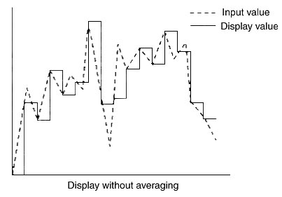
What is an Averaging?
Averaging provides a stabilized display by preventing the display from fluctuating due to significantly fluctuating analog inputs or reducing the effect of noise in input signals that contain noise.
Note: The display shows the value measured by sampling.
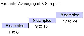
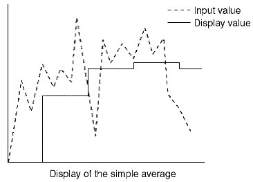
What is Simple Average?
After taking n samples (measurements) this function displays their average value.
The display continues to show the previous value until n samples have been measured.
The displayed value is just the average of n samples, so the previous set of data is unrelated.
This function is useful when you want to lengthen the time between display updates.
Any number of samples can be selected for the simple average.
Note:The output responsive is slower when the readings are averaged.
Applicable models: K3HB-X, K3HB-V, K3HB-S, K3HB-H, K3HB-R, K3GN, K3MA-J, K3MA-F, and K3MA-L Digital Panel Indicators
What is Moving Average?
Each time a reading is sampled, the last n samples (including the new reading) are averaged and displayed. The new average is related to the previous average.
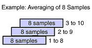
This function can eliminate periodic noise superimposed on the input signal.
The number of samples can be selected for the moving average.
In the K3HB-X, K3HB-V, K3HB-S, K3HB-H, and K3HB-R Digital Panel Indicators, the number of samples can be set to 2, 4, 8, 16, 512, or 1,024 samples.
Applicable models: K3HB-X, K3HB-V, K3HB-S, K3HB-H, and K3HB-R
Let me know about the noise suppression of the Digital Panel Meter.
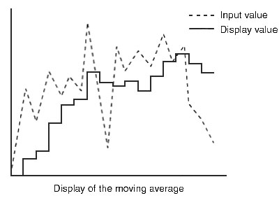
Place the Digital Panel Meter away as far as possible from equipment generating strong high frequency wave or surge.
Install a surge absorber or a noise filter into peripheral equipment such as motor, transformer, solenoid, magnet coil which especially contains inductance component.
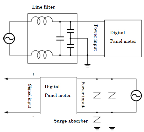
To prevent inductive noise, wire the terminal block of the unit separately from the high-voltage and large-current power line. Furthermore, avoid parallel wiring or shared wiring paths with power lines. It is also effective to separate the pipe line and the duct or to use shielded cables.
In the case when a noise filter is used with the power source, install the noise filter as close as possible to the Digital Panel Meter after checking the power voltage and current.
K3HB-X, K3HB-V, K3HB-S, K3GN, K3MA-J, K3TE, K3TF
Separate a lead wire connecting a temperature sensor and the unit from the power supply line and the loading line in order to avoid the influence of induction.
If it is used close to the radio, TV and wireless devices, it may cause poor reception.
What kind of functions does the ThermoTools provide?
ThermoTools is a software utility for setting the parameters of Temperature Controllers and Digital Panel Indicators. Most of the parameters that are set using the front panel keys of these devices can be set with a personal computer using ThermoTools.
The utility also has an online data logging function for collecting data and a data log preview function for displaying data trends. However, because these are simplified functions, they are not suited for permanent connection.
Logged data can be saved either as a text file or a CSV file.
Applicable models: ESTT ThermoTools Support Software
Can Support Software "ThermoTools" be connected to a USB port?
It can be connected to a USB port by using the K3SC Interface Converter. Refer to the K3SC product page for details.
The K3SC does not come with a USB cable. Use a commercially available USB cable or the OMRON XM7Z-200AB-FC2.
Which products can Support Software "ThermoTools"?
"ThermoTools" can be used with the E5[]R, E5[]N, E5[]K, E5ZN, and E5ZE Temperature Controllers; the K3N[] and K3GN Digital Panel Indicator; and the H8GN Timer/Counter, all of which support communications.
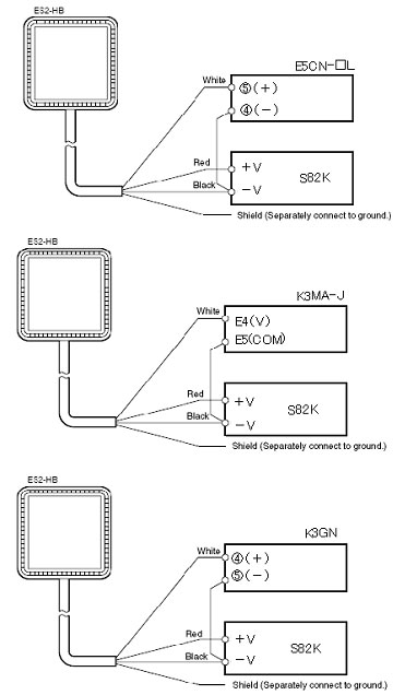
What Controllers can be used with ES2-THB Temperature/Humidity Sensors?
The humidity output of ES2-THB is a 1 to 5-V linear output for a humidity of 0% to 100%. Select a Temperature Controller that supports a 1 to 5-V input, and set the input range to 1 to 5 V for the Controller.
E5CN-[]L Series: General-purpose 48 x 48-mm Temperature Controllers with PID control
K3MA-J Series: Process Meters with 14.2-mm character height, high visibility, and comparative outputs or display only
K3GN-series: Compact 48 x 24-mm DIN Digital Panel Indicators with comparative outputs
A 24-VDC power supply is required for the Sensor.
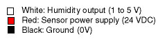
How do I wire ES2-HB Humidity Sensors and Controllers?
There are three wire from ES2-HB: white, red, and black.
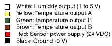
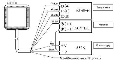
How do I wire ES2-THB Temperature/Humidity Sensors and Controllers?
There are six lines from ES2-THB: white, yellow, green, brown, red, and black.

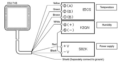
Wiring for E5CS Temperature Controllers are marked on the plug-in terminals.
Be careful, because the terminal block model has different terminal numbers.
 Automation Systems
  Motion & Power Solutions
  Safety, Vision and IDENT
  Sensing Solutions
  Control Components
  Switching & Accessories
  Switchgear and Trolley Systems
  Process Weighing
  LED Lighting
  Omron
Omron
 Mitsubishi
 Delta
Delta
 Autonics
 Inno
Inno
 Honeywell
 Novotechnik
 Orientalmotor
 Microscan
 IPA
IPA
 Technomech
 Intech
 IOT & Traceability
 Project & Panel Engg.
 Application Case Studies
 Solutions by Industry
 Solutions by Process
 Solutions by Product
 Corporate Information
 Company Profile
 Quality Policy
 Mission Statement
 Chairman's Message
 Intech Group Companies
