Frequently asked questions and answers for Photoelectric Sensors - Industrial Automation
Question
To use the light of a Photoelectric Sensor through the hole, how large the hole should be?
Answer
Please make the hole of the same size as the lens diameter basically.
Please refer to the following so that the idea is different depending on the sensing method.
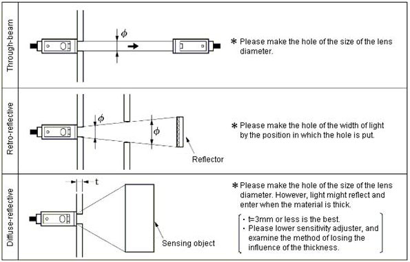
1. Idea to use the light through the hole
Please make the hole of the same size as the lens diameter to secure corridors of light regardless of the through-beam or the reflective.
When holes are smaller than the lens diameters, the rated sensing distance might not be satisfied because the amount of light decreases.
2. Notes by the sensing methods are as follows
Question
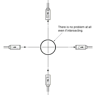
Isn't there problem even if two light emitted from Photoelectric Sensor of different place intersects?
Answer
There is no problem at all.
Question
What is "Wavelength of light "?
Answer
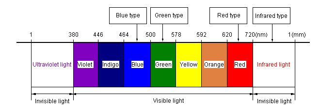
Light is a kind of electromagnetic wave and has various wavelengths such as visible light, invisible ultraviolet light and infrared light
Description
Light is a kind of the same electromagnetic wave as the electric wave. It has various wavelengths such as visible light, invisible ultraviolet light and infrared light.
Light source used for photoelectric sensors is four types that they are blue, green, red and infrared.
When using a Fiber Unit mounted to a movable part, are there models that are less affected by repetitive bending?
AnswerSeven models are recommended: E32-T11 Fiber Unit, E32-T21, E32-T22B, E32-D11, E32-D21, E32-D21B, and E32-D22B. (These have a bending radius of R4.)
The allowable bending radius of most Fiber Units is 25 mm minimum. Only the seven models listed above have an allowable bending radius of 4 mm. The fiber flexing characteristics have a strong relationship with the bare fiber diameter (see note 1). A bending radius that is 3 times or less the diameter exerts excessive force on the fiber and reduces the optical characteristics (see note 2 on light intensity).

Note:
1.Flexible Fiber Units (E32-[][]R) have an allowable bending radius of 1 mm, but do not handle repetitive bending well, so they should not be mounted on movable parts.
2.The light intensity of a Through-beam model is reduced to 50%, which reduces the sensing distance by about 30%.
3.
The Fiber Units listed above have a structure that strongly withstands the bending radius R by using fibers with ultra-small diameters.
Note:Flexible Fiber Units (E32-[][]R) have an allowable bending radius of 1 mm, but do not handle repetitive bending well, so they should not be mounted on movable parts.
What's the difference between a Reflective Fiber Unit and a Coaxial Reflective Fiber Unit?
AnswerThe sensing surfaces of the Fiber Units differ as shown below. Each is used for a different type of application.
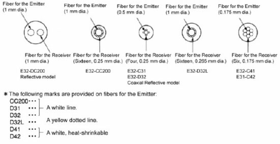

Note:The set directions for the Fiber Head are  and
and 
By what principle is the distance-setting Photoelectric Sensor detected?
PSD and the dual photodiode are used for the light receiving element and the distance to the sensing object is judged by detecting the reflected light spot position on the light receiving element.
The beam from the light emitting element (LED) is squeezed with the light emitting lens, and irradiated to the surface of the sensing object. And, a part of the diffuse reflected ray makes the spot on PSD through a light receiving lens.
The spot of light is made in "a" point when the sensing object is at the position of "A" that is the comparatively short distance and "b" point when it is at the position of "B" that is the long distance.
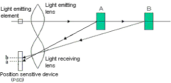
Therefore, if the spot position ("a" point and "b" point) on PSD is detected, the point turned on and the point turned off are set on PSD, and it can judge whether the sensing object is near or far compared with a setting distance. This is a principle of optical triangular measurement.
It is the E3G-L to use this principle.
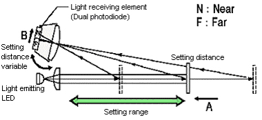
The beam from the light emitting element (LED) is squeezed with the light emitting lens, and irradiated to the surface of the sensing object. And, a part of the diffuse reflected ray makes the spot on the dual photodiode through a light receiving lens.
The position of the dual photodiode is adjusted so that N side and F side of the dual photodiode become the same amount of receiving light, and it is a setting distance. It is judged that the sensing object is nearer than a setting distance when the amount of receiving light is N>F, and judged that the sensing object is further than a setting distance when the amount of receiving light is N
They are the E3Z-LS and the E3S-CL to use this principle.
No influence of the background object and the color or regardless of the amount of reflected light so that the distance-setting detects the receiving light position of the reflected light, and steady detection is possible.
Is there a method of simply checking the trouble of a Photoelectric Sensor?
If the tester is used, it is possible to check it simply.
It is checked in the following method whether the control output operates normally with a tester.
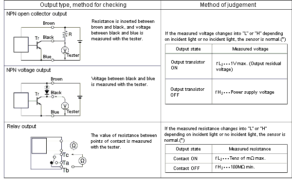
*This is simply operation check, and judges only the trouble of the control output.
Can other models of Reflectors be used with Retroreflective Photoelectric Sensors instead of the supplied Reflectors?
Yes, these Reflectors can be used: E39-R1, E39-R1S, E39-R2, E39-R3, E39-R9, E39-R10, E39-RS1, E39-RS2, and E39-RS3.
This does not apply, however, to Photoelectric Sensors for detecting transparent objects (E3Z-B, E3S-R, E3S-CR62/67, E32-R21, and E32-R16) or to the E3T.
Explanation:
The following table gives the sensing distances for the Reflectors listed above.
Example: E3Z

Note: Tape Reflectors (E39-RS1, E39-RS2, and E39-RS3) can be used cut to the desired size.
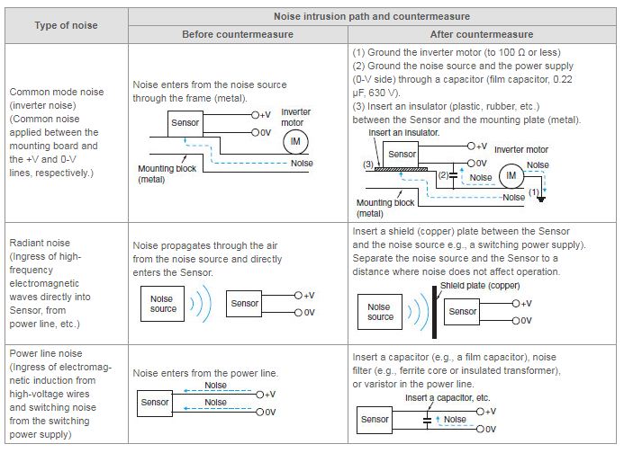
Our Photoelectric Sensors malfunction when the power supply of an inverter motor or other equipment is switched ON or OFF. What's causing this, and what can we do to resolve it?
It's possible that the malfunction is due to electrical noise. Try a countermeasure for noise. Different countermeasures should be used depending on factors such as the path of noise entry, the frequency component, and the peak value. Typical countermeasures for various types of noise are shown in the following table.
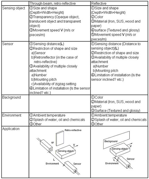
What are findings when a Photoelectric Sensor is selected?
Please confirm below findings.
How do the indicators on Photoelectric Sensors operate?
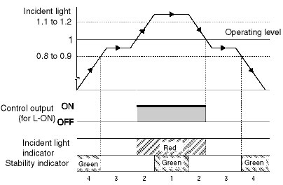
There is a stability indicator (green) and an incident light indicator (red). There are four operation patterns depending on the amount of incident light.
The stability indicator shows the excess gain for temperature, voltage, dust, or other changes in the environment after installation.
The incident light indicator shows the amount of light entering the receiver.
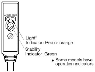

Note:The operating level is 1.
The following figure shows indicator operation on a graph.
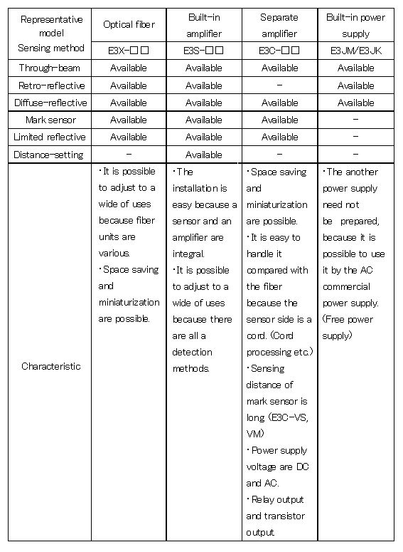
What is a Photoelectric Sensor?
A photoelectric sensor is the one to detect presence and the state of the object by the change in light.
Amount of light (luminance) is converted to an electrical signal, certain standard is set to a level of the electrical signal, the output is ON or OFF whether a level of an electrical signal (amount of light entered) is high or not than the standard.
What does the reversing polarity of power supply cause?
Although it differs depending on the model, it doesn't operate at all (it is not destruction) or the operation mode is switched.
1. The sensor is not destroyed because the protection diode against reverse connection is certainly in it.
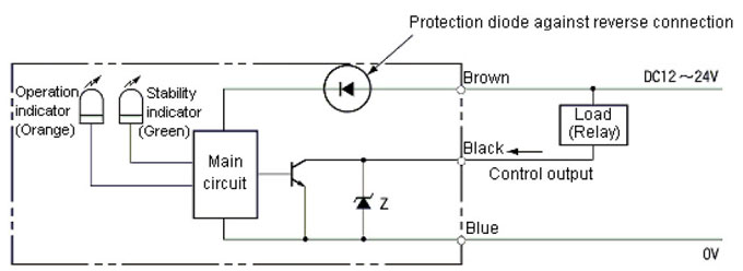
2. The diode bridge is in the power supply input, and the operation mode is switched. (*1)
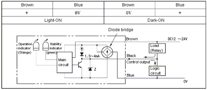
(*1.)E3S-GS, E3S-VS, E3L, E3S-R[]E[]series
(Refer to the applicable data sheets for details.)
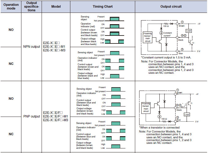
What is the difference of NPN transistor output and PNP transistor output of the sensor?

(1) NPN output type is used when connecting a load between power supply + and sensor output terminal.
(2) PNP output type is used when connecting a load between sensor output terminal and power supply -. This type is used a lot in Europe from the viewpoint on safety because the load is not driven even if somewhere of the wiring connected with the sensor output terminal is short-circuited with power supplies in some factors.
(3) The following is output circuit diagram of the E2E as typical.
What is the repeat accuracy for Photoelectric Sensors?
The accuracy depends on whether the Sensors are Through-beam or Reflective Sensors. The following table provides a general guide.
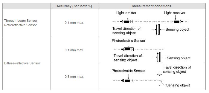
Note:
1.The values for accuracy are for reference only.
2.For Photoelectric Sensors, the repeat accuracy is the range of measurement error if the voltage, temperature, sensing distance, sensing object, and angle of the sensing object are the same.
Is the serial connection possible in a Photoelectric Sensor?
No, it is not.
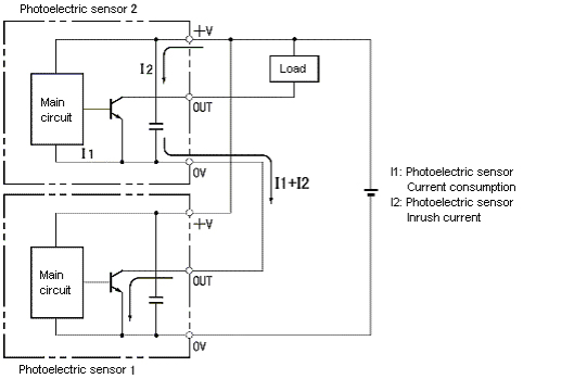
When photoelectric sensor 1 is turned on, the voltage is supplied to photoelectric sensor 2 in above figure.
At this time, inrush current I2 when the power supply of photoelectric sensor 2 is turned on flows to the output of photoelectric sensor 1. (It is about 0.5 to 1A instantaneously in charging current of capacitor.)
The output short-cut protection circuit* of a photoelectric sensor works by this inrush current I2, and the output of photoelectric sensor 1 is turned off.
As a result, the voltage is not supplied between power supplies of photoelectric sensor 2 and cannot be operated. Therefore, the serial connection cannot be connected.
*Output short-cut protection circuit:
It is the circuit that turns off output detecting the current and protects transistor, when overcurrent (above rated load current) flows to output.
Please use the serial connection by the combination with the sensor controller.
What is the MSR (Mirror Surface Rejection) function of Retroreflective Photoelectric Sensors?
MSR is a function of Retroreflective Photoelectric Sensors to receive only the light reflected from the Retroreflector by using the characteristics of the polarizing filter built into the Sensor and the characteristics of the Retroreflector.
Explanation:
1.Light that passes through the polarizing filter at the light emission side becomes horizontal.
2.Light will change from horizontal to vertical if it is reflected on the triangular pyramid on the Retroreflector.
3.The vertical reflected light passes through the polarizing filter at the light receiving side and reaches the light-receiving elements.
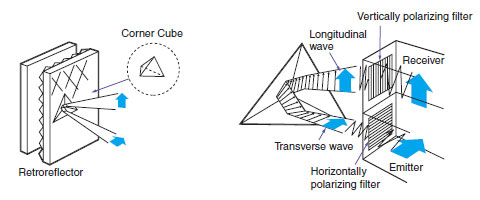
Using a Sensor with MSR is ideal for detecting mirrors or other mirror-like objects. By using the principles described above, a Sensor with MSR can detect a mirror-like object as shown in the following figure.

Note:If MSR is not used, the light reflected on the mirror-like object will be received, which will make it impossible to detect the object. The light will not be polarized at the object, and so the polarizing filter at the light-receiving side will prevent the reflected light from being received horizontally. This makes it possible to detect even mirror-like objects.
With Retroreflective Photoelectric Sensors, is there any change in performance depending on whether the Reflector is placed vertically or horizontally?
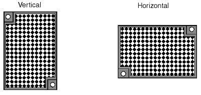
There is almost no change in ratings and performance.
Explanation:
The measurement values for Retroreflective Sensors in the catalog are for measurements with the Reflector placed vertically.
Are Photoelectric Sensors that can be used in locations subject to water available?
Using models that provide an IP67 degree of protection is recommended.
Explanation:
Items with an IP67 degree of protection satisfy the level of protection defined by IEC standard 60529 as shown in the following figures.

Typical models that provide IP67 protection are E3Z Series Photoelectric Sensors, E3S-A/B Series, and E32 Series.For details, refer to Sensors Catalog. Be sure, however, to heed the following precautions.
1.Malfunction may occur if there is water on the lens surface. (Through-beam Sensors and Retroreflective Sensors may incorrectly detect light interruption. Diffuse-reflective Sensors may incorrectly detect light incidence, and the sensing distance will decrease.)
2.Photoelectric Sensors cannot be used if the case or lens is immersed in oil. E3S-C Series with IP67g protection (oil-resistant construction) is recommended for use in locations subject to oil.
Can a Photoelectric Sensor with an Optical Fiber be used in an explosion-proof area?
Everything except the Amplifier Unit can be used in an explosion-proof area.
Explanation:
A Photoelectric Sensor with an Optical Fiber has no electrical parts, and it can thus be used even in hazardous, explosion-proof areas. However, the lens, the case, and the fiber covering are made of plastic, so they must be free from corrosion or deterioration (fogging) due to contact with solvents. As long fiber lengths are commonly used in explosion-proof areas, E32-T17L Fiber unit (standard fiber length: 10 m) is recommende
Are Photoelectric Sensors that can be used in water available?
Yes. It is possible to use E32-series Optical Fiber Photoelectric Sensors, which have no electric components. Usage, however, is restricted by the model. Refer to the following conditions.
Explanation:
Only models with IP67 protection can be used. Side-view models, however, including E32-T24/D24 and E32-T14L/D14L, cannot be used even with IP67 protection because in the water, light will continue through without being reflected. E39-F1/F3 also cannot be used because the effectiveness of the lens will be lost.
Also heed the following precautions when using Photoelectric Sensors in water.
1.Light will be attenuated in water. The transmission rate will be as given in the following table depending on the type of light source.

Note:Use an Amplifier with red light that has a high transmission rate if the Photoelectric Sensors are used in water.
2.Depending on the light source, further attenuation may occur if residue or dirt becomes attached to the fiber surface.
What is adjusted in the sensitivity setting of a Photoelectric Sensor?
(The E3X auto tuning type is excluded.)
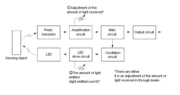
The amount of light received are adjusted, and the sensing distance is set.
(Refer to below figure)
The amount of light received or the amount of light emitted are adjusted, and the sensing distance is set.
* About the auto tuning amplifier, emitter current and the amount of light received are adjusted depending on a setting distance, and is set to the highest sensitivity.
What are the methods of mutual interference prevention in through-beam photoelectric sensors?
The light of other sensor do not enter own receiver.Prevention methods are as follows.
1. Setting of out of parallel operating range
Please confirm parallel operating range on the catalog, install setting distance of adjacent sensor by 1.5 times min.
2. Alternate arrangement setting of photoelectric sensor
Up to two sets of emitters and receivers can be attached closely as following alternative arrangement.

The light of the next emitter might be received when the sensing object is close to the photoelectric sensor.
3. Use of mutual interference prevention filter
By use of mutual interference prevention filter, up to 2 sets can be attached closely.Mutual interference prevention filters are as follows.
4. Mutual interference prevention by adjusting sensitivity
When sensing distance is shorter than rating setting distance, the influence of mutual interference is nothing by lowering sensitivity volume though it depends on the customer applications and the selection models.
What happens when direct sunlight strikes to the lens of the receiver?
Even if the light of a emitter is received, the sensor is the light shielding, or even if the light of a emitter is intercepted, the sensor is light entering, when direct sunlight enter the receiver. Therefore, please use the ambient illuminance by the sunlight 10,000 lx max as described to ratings/characteristics of the catalog.
Photoelectric sensors emit light by pulse and it turns on/off by level of the amount of light received.
The sunlight deletes the received light signal of the emitter and the sensor is the light shielding when direct sunlight strikes to receiver.
Additionally, even if the light of an emitter is intercepted, direct sunlight is considered as receiving signal and the sensor is light entering.
Therefore, please use the ambient illuminance by the sunlight 10,000 lx max.*
* The Value of the illuminance is approx. 10,000 lx max in shade. This value is changed the sunlight power. So, the value is just for your reference.
By what principle is the limited reflective Photoelectric Sensor detected?
In the optical system of the limited reflective sensor, only the regular reflection of a certain limited distance is received because the emitter axis intersects with a receiver axis in the same inclination ?.
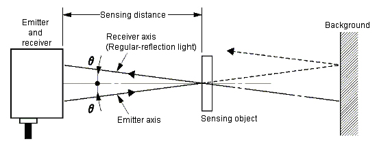
In the optical system of the limited reflective sensor, the emitter axis intersects with a receiver axis in the same inclination ? as shown in figure.
Only the regular reflection of a certain limited distance is received with such an optical system.
Therefore, only the object within the range where the emitter axis intersects with a receiver axis will be detected.
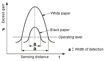
Moreover, the distance that reaches the peak of the excess gain never changes by the difference of the color because it uses the regular reflection.
(However, the width of detection shortens by the amount of light reflection decrease.)
Can a Photoelectric Sensor be used in outdoor?
A photoelectric sensor doesn't warrant use in outdoor.
The sunlight deletes the light signal of the sensor and the sensor is the light shielding, or even if the light of a photoelectric sensor is intercepted, direct sunlight is considered as receiving signal and the sensor is light entering, when direct sunlight strikes to the lens of the receiver.
Additionally, the temperature of the sensor becomes more than the operating ambient temperature by direct sunlight, and the sensor might be destroyed.
Material used for case deteriorate due to ultraviolet light included in direct sunlight, rapid temperature change and icing.
As for through-beam and retro-reflective, the light of the sensor diffuse by rain and fog, and might be dark-ON operation by attenuating the amount of receiving.
As for diffuse-reflective, the light of the sensor reflects to rain and fog, and might be light-ON operation by receiving light
Though it is not guaranteed when the sensor is unavoidably used, please avoid direct sunlight and wind and rain, and do not freeze by using a metallic type.
However, the malfunctions might be caused by rain and fog.
How is the UL standard of the sensor of the DC power system treated?
It is not necessary to use the UL standard certificated models in this case.
Please use the power supply certificated to the class 2 complying with the UL1310.
When you need to use the UL standard certificated sensors of the DC power system, Omron can provide the sensors that is certificated with the UL standards under the condition of "using in class 2 circuits".
Omron can provide the sensors with the UL standards certificated name-plate that is shown under the conditions of using in class 2 circuit.
The Reflector is fogged up. Is there any way to improve the situation?
Use E39-R1K Reflectors with a anti-fog coating. Regular Reflectors become fogged up when the temperature changes from -5°C to room temperature. Reflectors with anti-fog coating can withstand temperature changes from -25°C to room temperature
What are the differences between E39-R1 Reflectors and E39-R1S Reflectors?
E39-R1S has better reflection efficiency and directionality than E39-R1, so more light returns to the receiver, which enables a longer sensing distance.
For reference, the sensing distance for E3Z-R Photoelectric Sensors are 3 m with the E39-R1 and 4 m with the E39-R1S.
We use Through-beam Photoelectric Sensors and malfunction occasionally occurs. What is the cause of this problem and how can it be corrected?
The optical axis may have changed because of vibration or shock. If Sensors have a sensitivity adjuster, perform the following procedure to adjust the optical axis
1.Set the sensitivity adjuster halfway between MIN and MAX.
2.Adjust the optical axes of the emitter and receiver at that sensitivity.
Move the emitter up and down and to the left and right to adjust it to the center of the angle range for receiving light.
Move the receiver up and down and to the left and right to adjust it to the center of the angle range for receiving light.
3.Last, set the sensitivity adjuster to MAX.
Note:If Through-beam Sensors don't have a sensitivity adjuster, use a slit to attenuate the light.
Can a Slit and a Mutual Interference Protection Filter be used at the same time with E3S-AT Through-beam Sensors?
No, they cannot. If they are used at the same time, the Slit will become tilted, and the sensing distance will be extremely short. Do not use them at the same time.
Is it acceptable to wipe off dirt from the lens surface of Photoelectric Sensors with alcohol?
No, it is not. The lens of the Photoelectric Sensors are basically plastic. Do not use organic solvents, such as thinners or alcohol, to wipe the surface. The lens surface may become clouded or cracked. Gently wipe away dirt with a dry cloth or use water.
The same applies to the Sensor case if the case is plastic.
What role does the Slit play for Through-beam Photoelectric Sensors and how is it used?
The Slit is mounted on the emitter and receiver of Through-beam Photoelectric Sensors to decrease the lens diameter and narrow the light beam. This is done to increase the sensing performance for the smallest detectable object
One set of two Slits for the emitter and receiver is generally used mounted to the emitter and receiver of a Through-beam Photoelectric Sensor. It is also possible, however, to use a Slit on only either the emitter or the receiver, depending on the sensing distance and the size of the sensing object.
Slits, however, cannot be used on Reflective Photoelectric Sensors (e.g., Retroreflective, Diffuse-reflective, Convergent-reflective, or Distance-settable Sensors).
What are the differences between E39-R1 General-purpose Reflectors and E39-R1K Reflectors with anti-fog coating?
E39-R1K Reflectors are the same as E39-RQ, except they have an anti-fog coating added to the reflective surface. The anti-fog effect of the coating is similar to that used by ski goggles.
The sensing distance with E39-R1K is the same as with E39-R1. For example, with E3Z-R Photoelectric Sensors with built-in amplifier, the sensing distance is 3 m whether E39-R1 or E39-R1K is used.
We detect shiny objects using Retroreflective Sensors with the MSR (Mirror Surface Rejection) function, and malfunction occasionally occurs. What is the cause of this problem and how can it be corrected?
Retroreflective Sensors normally have the MSR function, and so shiny sensing objects can also be detected. Perform a test before using Sensors for sensing objects with an extremely high degree of shine or for objects to which transparent film is applied, such as those objects in the following list. Reflected light received from the object may result in unstable operation.
Examples of Sensing Objects with Possible Unstable Sensors Operation
1.Cardboard boxes covered with a transparent sheet (i.e., shrink-wrapped)
2.Semi-transparent resin cartons
3.Aluminum vapor-deposited shiny vinyl bags
4.Cigarette packs covered with transparent vinyl
Using Through-beam Sensors are recommended for detecting sensing objects like those listed above.
Are heat-resistant Photoelectric Sensors available?
Yes, Fiber-type Photoelectric Sensors are available with heat resistance specifications. The heat resistance specifications, however, apply to Fiber Units only, and not to Amplifier Units.
Detecting wafers in high-temperature environments
E32-T61-S Fiber Units


Note:The sensing distances apply for use in combination with the E3X-DA-S Amplifier Unit (general-purpose, standard mode).
Which hole of the Amplifier Unit can the Through-beam Fiber Unit be inserted into?
It makes no difference which hole it is inserted into, because there is no distinction between the two fibers for a Through-beam Fiber Unit.
With a Coaxial Diffuse-reflective Fiber Sensors (such as the E32-C31), the holes that the fibers are inserted into are set for the receiver and emitter.