Frequently asked questions and answers for Photomicro Sensors - Industrial Automation
What is the difference between a Photomicrosensor for industrial equipment and a Photomicrosensor to be built into devices?
Since the Photomicro Sensors for Automation System are developed mainly for building facilities and Factory Automation Systems(FA), they have the following features. However, since these features are not common to all models, be sure to check the specifications of each model individually.
(1) Wide operating voltage range(f.e.5VDC to 24VDC)
(2) The operation indicator light is built-in
(3) Output switching capacity has the direct connection with the Programmable Controllers and the Relay
Since the Built-in Type Photomicro Sensors are developed to be built into consumer products(f.e. Video camera, Laser disc player, Microwave oven) and office automation equipment(f.e. Printer, Facsimile, Copier, Floppy-disk drive), they have the following features. However, since these features are not common to all models, be sure to check the specifications of each model individually.
(1) Operable mainly on 5VDC or 12VDC.
(2) Not be directly connected to the Programmable Controllers and the Relay due to the switching capacity limited to operating electronic circuits. Amplifier circuits are required for the direct connection with the Programmable Controllers and the Relay.
(3) Smaller in size, lighter in weight and lower in cost compared to the Photomicro Sensors for Automation System.
What are the electrical and optical characteristics?
Electrical and optical characteristics indicate the performance of the Photomicro Sensors under certain conditions. Most are indicated in terms of minimum and maximum values.
Basically, products are sold with performance to a standard provided by the manufacturer. Items indicated with maximum or minimum values are for lot inspections, and items indicated with typical values (TYP) are performance values that are assured or managed with periodic control.
Absolute maximum ratings and electrical and optical characteristics are included as main titles in the Photomicro Sensors catalog. (Similar expressions are used in catalogs for transistors, ICs, and other components.) The two expressions differ in meaning, and it is necessary to understand the difference.
In summary, the absolute maximum ratings indicate the usage restrictions and electrical and optical characteristics indicate the performance limits.
The output voltage of one Phototransistor is much higher than others. What's causing this and what can be done?
Cause:
There may be an error in the circuit constant setting. Specifically, the output voltage may be high because the load resistance connected to the receiver's phototransistor is too small.
Countermeasure: Set an appropriate load resistance value to correct the circuit constant.
Refer to the following example of incorrect operation with EE-SX1041 Photomicrosensor due to an error in setting the load resistance and the method for correcting error by calculating an appropriate load resistance value.
Reference Explanation:
Model: EE-SX1041
Example Name: Incorrect Operation Due to Error in Setting Load Resistance Values
Example description and cause: The load resistance value is too small, so the phototransistor cannot pass the circuit current.
(Optical current IL < Circuit current I2 + I3, so the phototransistor cannot pass the circuit current, and output V11 does not drop below the voltage to be detected, L.)
Example: Using the EE-SX1041 with the Following Circuit
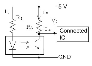
Circuit constants
R1 = 220Ω, RL = 10 kΩ
Specifications of Connected IC
Current I3 flowing from IC when input voltage is low: 0.1 mA
The following is a detailed explanation of the calculation. R1 = 220 M, so LED forward current IF = (VCC − VF)/R1 = (5 − 1.2)/220 = 17 mA. (Formula 1)
For the EE-SX1041, the standard value of light current IL = 0.5 to 14 mA (when IF = 20 mA). If IL is found using proportional calculation, IL = 0.425 to 11.9 mA (when IF = 17 mA). (Formula 2)
And, circuit current I2 + I3 = (VCC − VCE(sat))/RL + I3 = (5 − 0.1)/10 k + 0.1 = 0.59 mA. (Formula 3).
The relationship of the values found using formulas 2 and 3 is
IL = 0.425 mA < I2 + I3 = 0.59 mA, so the phototransistor will not pass the circuit current and the output will not reach L if the mounted phototransistor is mounted near the specified lower limit of light current IL (in this case, near 0.5 mA when IF = 20 mA).
(There is variation in the sensor light current IL, so even if there are no problems during the prototype stage, variations in the Sensor after starting mass production may result in incorrect operation. Always perform calculations and check that there will be no problem even if the Sensor is near the specified lower limit of the light current IL.)
Correction Procedure:
Change the load resistance RL.
(For the circuit above, set the load resistance RL to approximately 47 kΩ.)
Calculation Procedure:
Generally design the Photomicrosensor system anticipating a 50% reduction from the initial value of IL considering degradation over time and temperature characteristics.
Accordingly, the settings must be made so that IL x 0.5 > I2 + I3.
Calculating using the calculation example above,
IL = 0.425 mA x 0.5 > I2 + I3
0.212 > I2 + I3
0.212 > (VCC − VCE(sat))/RL + 0.1
RL > ((5 − 0.1)/(0.212 − 0.1)) = 43.8k Ω ,so
RL = Approximately 47 kΩ.
What are the absolute maximum ratings of Photomicrosensors built into Equipment?
Absolute maximum ratings specify the upper limit of usage conditions for factors such as the voltage, current, temperature, and power. These ratings indicate the limits over which the Photomicrosensor cannot be used even momentarily.
For Photomicrosensors and other semiconductor products, these ratings absolutely must not be exceeded, as the term "absolute" indicates.
This is a strict rule. If the Photomicrosensor is used in excess of theses ratings, reliability will be markedly damaged, and OMRON shall bear no manufacturer responsibility for any resulting deterioration or damage.
Be careful to design the system so that operation will be performed within these ratings. In actual operation, derating is used to perform operation at some percentage below the ratings.
Explanation:
Absolute maximum ratings and electrical and optical characteristics are included as main titles in the Photomicrosensor catalog. (Similar expressions are used in catalogs for transistors, ICs, and other components.)
The two expressions differ in meaning, and it is necessary to understand the difference.
In summary, the absolute maximum ratings indicate the usage restrictions and electrical and optical characteristics indicate the performance limits.
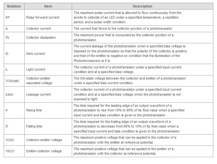
What is the notation and terminology for a Phototransistor output?
The following table provides a description of notation and terminology used in catalogs for Photomicrosensors built into equipment with a phototransistor output.
What is the response frequency?
The frequency at which an object satisfying specified conditions (size, transparency rate, reflection factor, sensing distance, and power supply voltage) can be repeatedly detected.
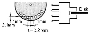
For EE-SX47[]/67[]-series (slot-type/non-modulated) Photomicrosensors, the response frequency is listed as 1 kHz (3 kHz average) in the response frequency column in the catalog's ratings and specifications. (See note 1.)
This means that OMRON ensures a response frequency of 1 kHz. This value takes product variation into account.
The average of the actual measured response frequencies is the value of 3 kHz listed in parentheses.
Use the average value as reference, but actually design the system using the ensured value of 1 kHz.
Note 1:
The response frequency above is measured for a disk rotated as in the following figure.
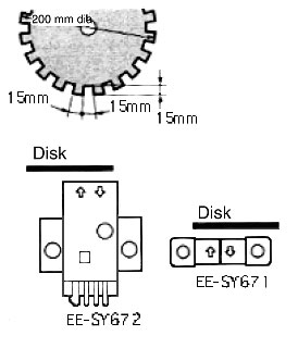
For EE-SX671/672-series (reflective connector/non-modulated) Photomicrosensors, the response frequency is listed as 50 Hz (500 Hz average) in the response frequency column in the catalog's ratings and specifications. (See note 2.) The meanings of the ensured value and the average value are as explained above in example 1.
Note 2:
The response frequency above is measured for a disk rotated as in the following figure.
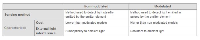
What are modulated and non-modulated of Photomicrosensors Used for Industrial Equipment?
The following table shows the sensing method and characteristics for modulated and non-modulated light.
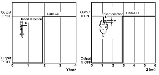
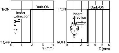
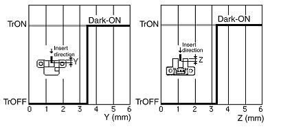
What are sensing position characteristics (for slot-type models) of Photomicrosensors Used for Industrial Equipment?
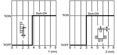
The sensing position characteristics measure the point where the Photomicrosensor turns ON when an opaque workpiece is inserted from the direction shown in the following figures.
With EE-SX77/87 Photomicrosensors, for example, the horizontal sensing position is 1.9 mm from the side of the Sensor (the Y portion in the following figures), and the vertical sensing position is 2.9 mm from the top of the Sensor (the Z portion in the following figures).
These values, however, are only typical examples. The sensing position depends on variations in the light-emitting and light-receiving elements, temperature characteristics, and degraded service life of the light-receiving element.
Is there an easy way to check whether the control output of the Photomicro Sensors is operating properly?
The operation can be easily checked with the following procedure using a tester.
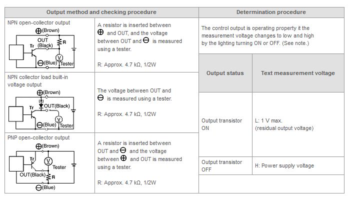
Note:This is a simple check that determines only whether the control output is malfunctioning.
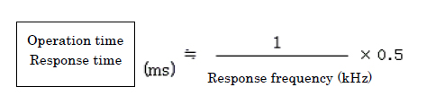
How are the operation time and the recovery time of the Photomicro Sensors calculated?
The maximum value of the operation time and the recovery time is calculated as follows.
Are Photomicro Sensors with the Light-ON/Dark-ON selectable operating mode available?
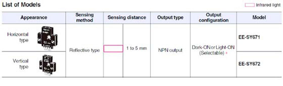
Yes. The EE-SX67[] Series for Through-beam type (with slot), the EE-SY671/672 for Reflex type are available.
Built-in models with 5 to 100mA direct switching capability
Light-ON⁄Dark-ON selectable operating mode (output configuration)
Response frequency as high as 1 kHz
Easy operation monitoring with bright light indicator
Wide operating voltage range from 5 to 24 VDC
Models (EE-SX[][][]A,[][][]R) with operation indicators that are lit when light is interrupted (when sensing objects are detected) are available

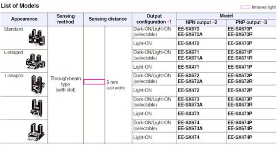
*1. The Dark-ON⁄Light-ON (selectable) models are normally used as dark-ON models. To use them as light-ON models, short-circuit the L terminal and positive (+) terminal.
An EE-1001-1 Connector with the terminals already short-circuited is also available. Additionally, Connector "EE-1001", "EE-1009", Cable Connector "EE-1006", "EE-1010", and Robot Cable Connector "EE-1010-R" with the open terminals are available.
*2. Model numbers ending in suffix A (e.g., EE-SX670A) indicate models for which the operation indicator will turn ON when the light is interrupted.
*3. Model numbers ending in suffix R (e.g., EE-SX670R) indicate models for which the operation indicator will turn ON when the light is interrupted.
Models with sensitivity adjuster
Easy adjustment with a built-in sensitivity adjuster
Easy operation monitoring with bright light indicator
Compact design with a special built-in IC makes it possible to directly switch currents up to 100mA.
Wide operating voltage range from 5 to 24 VDC
Smooth connection with Programmable Controllers as well as a variety of ICs and Relays is possible.
The Dark-ON⁄Light-ON (selectable) models are normally used as dark-ON models. To use them as light-ON models, short-circuit the L terminal and positive (+) terminal.
An EE-1001-1 Connector with the terminals already short-circuited is also available.
Additionally, Connector "EE-1001", "EE-1009", Cable Connector "EE-1006", "EE-1010", and Robot Cable Connector "EE-1010-R" with the open terminals are available.
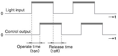
What is the response time of Photomicrosensors Used for Industrial Equipment?
The response time is the delay between when the light input is interrupted and when the control output operates or is released. Generally, the operate time (tON) is almost equivalent to the release time (tOFF).
Can Photomicrosensors be used on locations subject to external light interference?
Install the Sensors in a location and using methods to ensure that no ambient light will interfere or use non-modulated Photomicrosensors for Industrial Equipment that are resistant to external light interference.
What is the difference between EE-1009 Connectors and EE-1001 Connectors?
EE-1009 has a lock mechanism to prevent connectors from disconnecting, but EE-1001 has no lock mechanism.
What is the difference between EE-1010 and EE-1010-R Connectors with Cables?
EE-1010 uses a regular cable, but EE-1010-R uses a robot cable, which provides superior flexibility. (The robot cable can be bent more than approximately three times as many times as the regular cable. Use a bending radius of at least three times the diameter of the cable.)
Using EE-1010-R is recommended if the cable is to be connected to a moving part.
What is the difference between EE-1010 and EE-1006 Connectors with Cable?
EE-1010 has a lock mechanism to prevent the connector from being disconnected, but EE-1006 has no lock mechanism.
Let me know about the bend-resistant performance of a cable for the Robot Cable Connector "EE-1010-R".
A Robot Cable for the EE-1010-R has bending tolerance that is over three times higher than a common cable (electric cable) for the EE-1010.
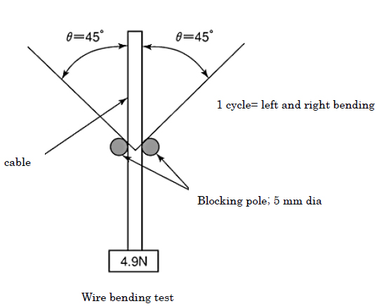
Refer to the following results of the Cable Bending Destruction Test.
To evaluate the bend-resistant performance of a normal cable (electric wire) for the EE-1010 and a Robot Cable (electric wire) for the EE-1010-R.
A Robot Cable (electric wire) for the EE-1010-R has bending tolerance that is over three times higher than a normal cable (electric wire) for the EE-1010
Robot Cable: Absolutely cut off by bending about 43000 times
Normal Cable: Absolutely cut off by bending about 12000 times
As shown in the figure 1, reciprocating bending at an angle of 45 degrees is given at a rate of 55 times per minute with a load of 4.9N. This procedure should be repeated until a cable is absolutely cut off.
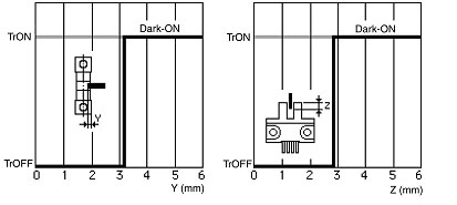
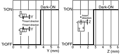
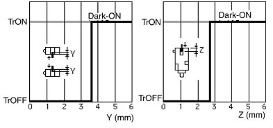
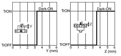
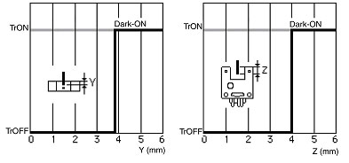
What are the sensing position characteristics of Slot-type Photomicro Sensors?
See the following diagrams.
Is there a way to convert NPN transistor output to PNP transistor output?
It can be converted by using an NPN/PNP Conversion Connector below. The connector, however, is not applicable to all models of Photomicrosensors. Be sure to check the items to find which Photomicrosensors are applicable.
Will a Photomicrosensor be damaged if the power supply is connected backwards or the output is short-circuited?
Yes, there is a possibility of malfunction from connecting the power supply backwards or shorting the output because the Photomicrosensor has no built-in reverse polarity protection circuit for the power supply or short-circuit protection circuit for the output. Care must be taken to avoid connection mistakes.
Can Photomicro Sensors be used with a Slit on the light emitting/receiving window?
No, it is not possible to use Photomicro Sensors with a Slit on the light emitting/receiving window.
Reference information:
Because the sensing performance of Photomicro Sensors does not have a margin as wide as that for Photoelectric Sensors, using a slit will cause the amount of light to be insufficient and result in failure to operate, or failure to operate due to temperature change or deterioration in the illuminating LED over time (even if initial operation was correct).
How large is the differential distance for Photomicro Sensors?
The distance depends on the model, but use the following values as a guide.
Why is a capacitor of at least 10 micron (micrometer) F required to extend the EE-SP Photomicro Sensors cable?
EE-SP Series uses an LED for pulse illumination (modulated light). A circuit to fully stabilize the power supply voltage is not built into the Sensors, and so the voltage supplied to the Sensors will fall when the LED is lit due to the cable resistance and LED current if the cable is extended. A capacitor must be inserted (as a smoothing circuit) to prevent unstable operation due to the drop in voltage.
Is a power supply polarity reverse protection circuit or output short-circuit protection circuit built into Photomicro Sensors?
Photomicro Sensors do not have a built-in power supply reverse polarity protection circuit or output short-circuit protection circuit. Care must be taken to prevent incorrect connection.
What happens if the L terminal for switching the operation mode of EE-SX47/67 or EE-SY67 Photomicro Sensors is connected to the negative terminal?
The operation mode will be the same as when the L terminal is open. Connecting the L terminal to the negative terminal will not result in failure or other problems, but the product is designed so that the L terminal is open or connected to the positive terminal, so leave it open or connect it to the positive terminal.
What are the dimensions of the slit for slot-type Photomicro Sensors?
It is the same size as the standard sensing object given in the catalog.
Example: Standard opaque sensing object measuring at least 2 x 0.8 mm for the EE-SX47/67 Series
Dimensions of emitter/receiver slit: 2 x 0.8 mm
Can the EE-SX671 Photomicro Sensor be used in a magnetic field?
Yes, it is fundamentally possible to use EE-SX671 in a DC magnetic field, but operation must be confirmed by testing if the magnetic field is strong (on the level of affecting electronic circuits) or if EE-SX671 is used near the source of a high-frequency magnetic field.
 Automation Systems
  Motion & Power Solutions
  Safety, Vision and IDENT
  Sensing Solutions
  Control Components
  Switching & Accessories
  Switchgear and Trolley Systems
  Process Weighing
  LED Lighting
  Omron
Omron
 Mitsubishi
 Delta
Delta
 Autonics
 Inno
Inno
 Honeywell
 Novotechnik
 Orientalmotor
 Microscan
 IPA
IPA
 Technomech
 Intech
 IOT & Traceability
 Project & Panel Engg.
 Application Case Studies
 Solutions by Industry
 Solutions by Process
 Solutions by Product
 Corporate Information
 Company Profile
 Quality Policy
 Mission Statement
 Chairman's Message
 Intech Group Companies
