Frequently asked questions and answers for Proximity Sensors - Industrial Automation
How do I interpret the catalog values for mutual interference with Proximity Sensors?
Refer to the following figures.
Use Sensors with the values in the following table or higher when they are mounted facing each other or in parallel.
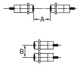
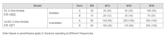
The values listed above are given in the precautions section of the catalog. Dimensions A and B are specified by the way in which the Proximity Sensors are arranged. If a gap cannot be provided between the Proximity Sensors, they can be used close together up to the catalog values in parentheses by using a standard model in combination with a model that has a different frequency.
Note:Two of the Sensors with a different frequency cannot be used near each other. Leave a gap of at least the value not in parentheses.
Why does the influence with a surrounding metal of the Proximity Sensor occur?
For the proximity sensor, when there are the metals other than the sensing object circumferentially, the oscillation that decreases when the sensing object approaches normally falls overall.
Therefore, the position of the sensing object when reaching at output ON level is farther than normal, the malfunction such as the extension of the sensing distance is caused.
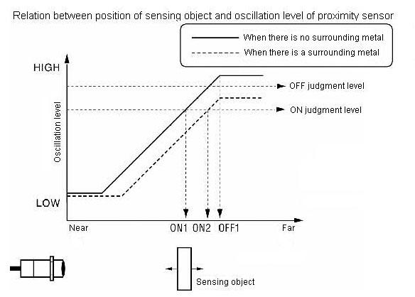
Relation between positions of sensing object and oscillation level of proximity sensor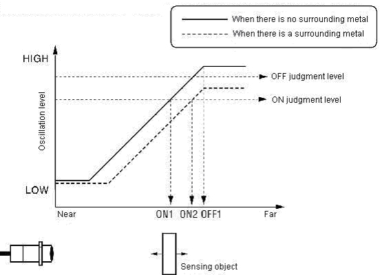
(1) The oscillation level of the proximity sensor falls as the sensing object (metal) approaches
(2) The oscillation level falls overall regardless of the presence of the sensing object when there is a surrounding metal.
(3) The ON/OFF judgment level of the proximity sensor is decided by height at the oscillation level.
(4) Operation is normal because ON point is ON1 and OFF point is OFF1 when there is no surrounding metal.
(5) ON point (ON2) when there is a surrounding metal is further than ON point (ON1) when there is no surrounding metal.
(6) There is no OFF point because it lowers more than OFF judgment level even when the sensing object is far and the oscillation level is high when there is a surrounding metal.
Why does mutual interference occur with Proximity Sensors?
If multiple Proximity Sensors are used, mutual interference occurs when the oscillating frequencies of the Sensors are close together. The oscillation widths will interfere with each other and malfunction or chattering will occur if the oscillating frequencies of neighboring Sensors are close together. To reduce this interference, Sensors with different frequencies are available to stagger the oscillating frequencies of the Proximity Sensors
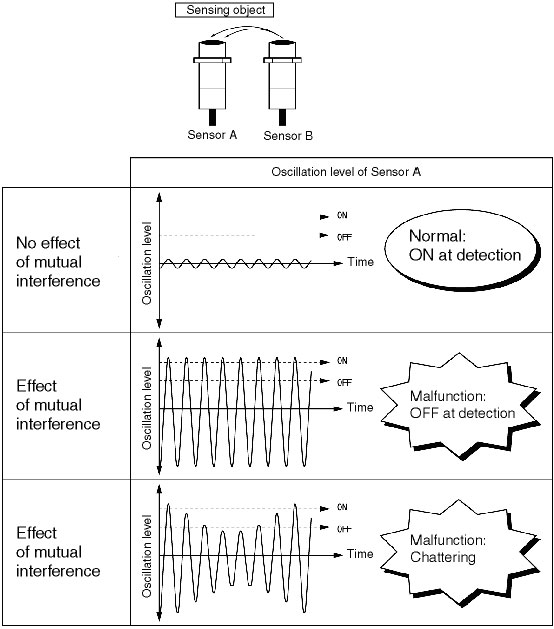
What malfunctions occur if there is mutual interference with Proximity Sensors?
Refer to the following figures, which apply to Sensor A being affected by Sensor B.
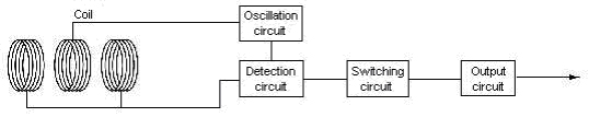
Please teach the principle of operation of Standard cylinder type Proximity Sensor the E2E Series.
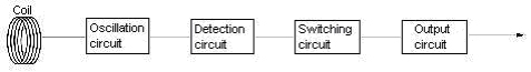
The circuit composition and the principle of operation are as follows.

That is called the high frequency oscillation type, the eddy current is generated on the metal surface by the metal's approaching the oscillation coil built into sensing surface, and the impedance of the detector coil changes by the electromagnetic induction action.
As a result, the oscillation circuit that oscillates in the high frequency cannot oscillate and the oscillation level decreases.
The approach of the sensing object is detected depending on the decrease degree at this oscillation level.
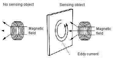
The eddy current is generated the higher the permeability of the sensing object like iron is, it is easy to for the sensor to detect it.
What are notes in the idea of the repeat accuracy of the Proximity Sensor?
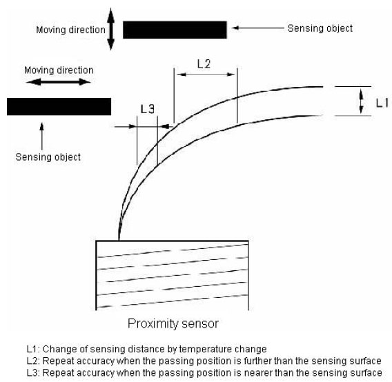
Factors that the sensing distance or area of the proximity sensor changes are an ambient temperature and an operating voltage, etc.
Moreover, It greatly influences repeat accuracy because there are piece-to-piece variations (rated sensing distance: ±10%), when two or more pieces are used by the same setting.
Therefore, please consider desired accuracy, sensing method, ambient environment, and installation error, etc. enough, and select the model because the difference is in repeat accuracy depending on ambient environment and piece-to-piece variations even if it is the same model.
Moreover, please note that the distance from the sensing surface is longer, variation is widely as shown in the below figure when the moving direction of sensing object is parallel to the sensing surface of the proximity sensor.
The eddy current is generated the higher the permeability of the sensing object like iron is, it is easy to for the sensor to detect it.
What series and parallel connections are possible with Proximity Sensors?
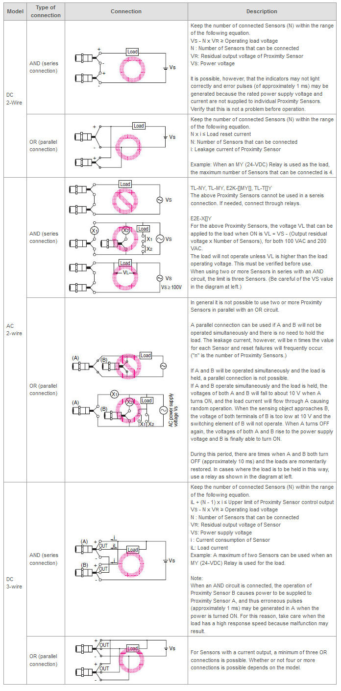
Note:When AND/OR connections are used with Proximity Sensors, the effects of erroneous pulses or leakage current may prevent use. Verify that there are no problems before use.
What happens if Proximity Sensors are used in high temperatures?
Generally, the sensing distance will increase at high temperatures, and so the operating point and reset point will both increase, the differential (i.e., the difference between the operating point and the reset point) will widen, and Proximity Sensors will tend to not reset even if it operates. If the temperature rises further and the operating point increases, Sensors will operate even if there is not a sensing object.
In addition to the change in the sensing distance, it is probable that Sensors will eventually fail, due to heat resistance temperatures for each component (e.g., electronic components, resin, and cables). Use Sensors within the specified temperature range.
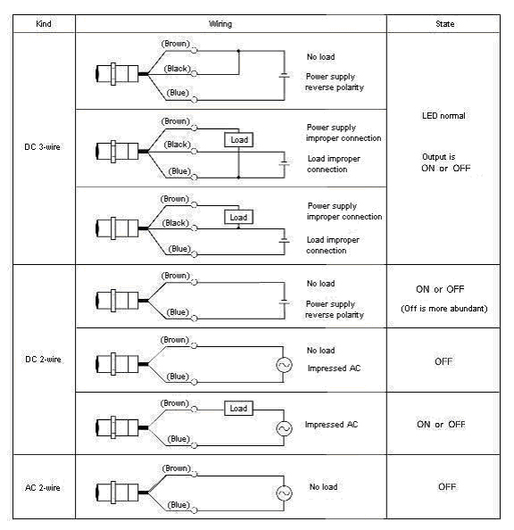
What malfunction occurs when the Proximity Sensor is wired by mistake?
Please note that there is a possibility of breaking down when wiring by mistake as follows;
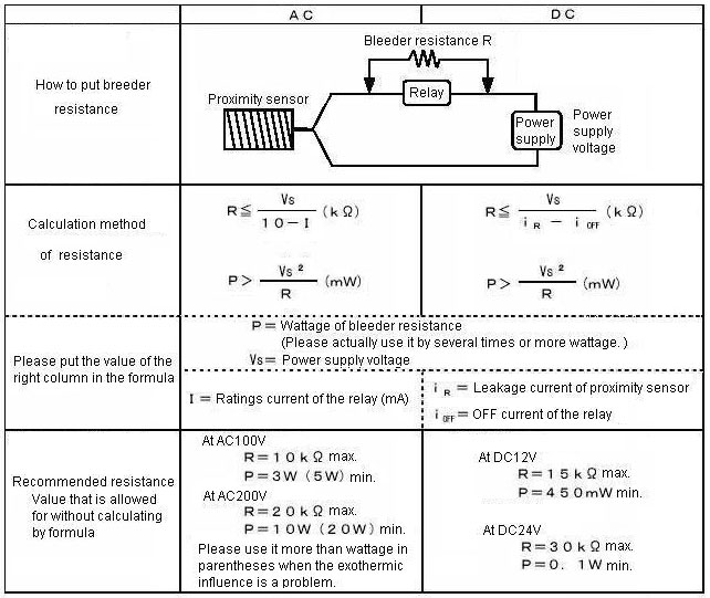
What are measures and malfunction mode when the relay of not being possible to connect it with the Proximity Sensor is connected?
When the proximity sensor does not meet the ON condition of the relay
When the proximity sensor does not meet the OFF condition of the relay
When the proximity sensor nearly meets the ON/OFF condition of the relay
There are no measures.
Please put the bleeder resistance in parallel with the load. (Refer to the figure below.)
What is the construction and the operating principle of the GLS Proximity Sensors?
GLS combines a reed switch and a permanent magnet.
As shown in the following figure, two reeds of electromagnetic material are inserted opposite each other with a gap in a glass pipe. This section is the contacts. (Refer to Figure 1.)
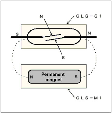
When the permanent magnet nears this section, a magnetic field causes the two reeds to be attracted to the N pole and S pole. The contacts operate due to attraction, and the contacts switch. (Refer to Figure 2.)
Figure 1: Basic Construction of a Reed Switch
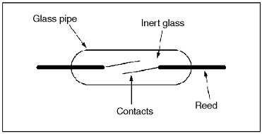
Figure 2: GLS Operating Principle
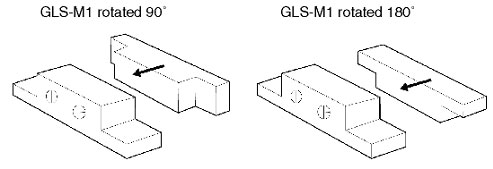
Will there be any problem if GLS Proximity Sensors are installed with the direction of the magnet section changed?
As shown in the following figures, there is no problem if the magnet section (GLS-M1) is rotated 180°. However, install it so that the direction of travel is in the direction of the arrow.
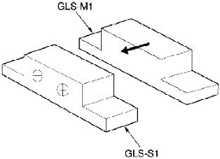
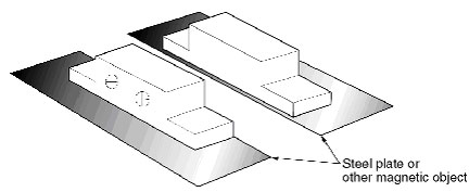
The sensing distance will decrease if the magnet section is mounted on a steel plate or other magnetic object. Check the sensing distance before operating GLS.
What kind of consideration points does it have when the relay is connected to Proximity Sensors?
Connected condition is not suitable and it is not likely to be able to combine when the relay is connected as a load of the proximity sensor.
Please judge whether to connect it from ON/OFF condition of the relay and an electric characteristic of the sensor.
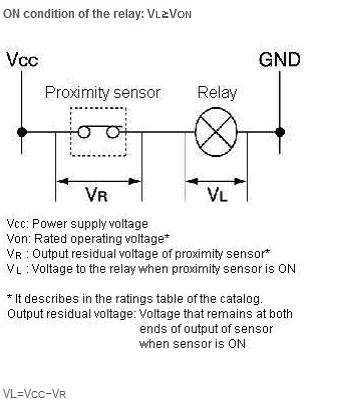
Please confirm above ON condition is satisfied after calculating VL from above formula.
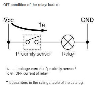
What is the OFF current of the relay?
The OFF current is not provided for by ratings of the relay.
Please calculate from the following formula.
(0.8 is variation coefficient of the relay)
Because an enough current to operate the proximity sensor is not supplied when the ratings current of the relay is below minimum of the control output of the proximity sensor, it does not operate normally.
What precautions are there for using Proximity Sensors at a closer distance than the distance given in the catalog for preventing mutual interference?
Consider the following points to determine if Proximity Sensors are placed closer together than the distance given in the catalog. There is variation in the oscillating frequency of each Sensor within a specific range. The effects of mutual interference occur when the oscillating frequencies are close together. Normally, the rate at which mutual interference will occur depends on the probability that oscillating frequencies with variation will be close together.
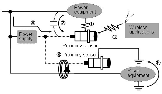
What are kinds of noises that influence the Proximity Sensor?
The kind of the noise is as follows if it classifies it by the propagation pathway.
Direct radiation noise from noise source (1)
Induction noise from power line to signal line (2)
Induction noise from power line to signal line (3)
Noise from power supply line (4)
Noise from earth conductor (5)
Noise from wireless applications (6)
Are Proximity Sensors that can be used outdoors available?
Proximity Sensors that are used outdoors may not last.
Degradation of Resin Material Due to Ultraviolet Light
The environmental resistance (i.e., water resistance) of Proximity Sensors may be degraded because of degradation of the internal filling resin, sensing surface resin material, or cable sheath due to ultraviolet light.
Stress on Filling Resin Due to Sudden Temperature Changes
Rapid changes in temperature that accompany exposure to direct sunlight or changes in weather may cause swelling and shrinking of internal filling resin and other stress on Sensors.
Degradation of Resin Due to Freezing
Freezing of Proximity Sensors may cause cracks in the resin material of the sensing surface and degrade the environmental resistance (i.e., water resistance).
Proximity Sensors can be used with a hood or installed in a resin box to prevent exposure to ultraviolet light and freezing.
The Proximity Sensor remains to turn on while using the Proximity Sensor near the magnetic field source. How to avoid this phenomenon? And why does it occur?
The proximity sensor receives the influence of the magnetic field in the following process, and causes the malfunction.
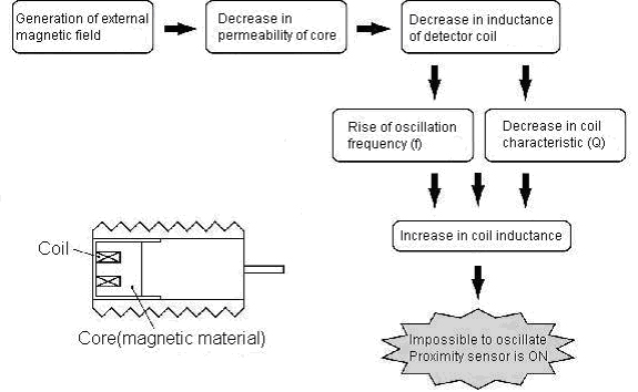
(1) The magnetism of the magnetic field source or the proximity sensor is blocked by an iron plate (magnetic).
(2) We recommend replacement for the capacitive proximity sensor (the E2K Series, E2KQ Series and E2J Series).
Because the capacitive proximity sensor does not use the core (magnetic material) in the above figure, the influence of the magnetic field is not received.
(3) For high frequency oscillation proximity sensor (the E2E Series and TL Series, etc.), please consider that DC/AC magnetic field is 200G or less on the sensing surface of sensor when the sensor is installed.
If it is 200G or less, it is possible to use it.
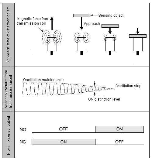
What is "NO (normal open)"? What is "NC (normal close)"?
When there is a sensing object within sensing range, transistor output is ON.
When there is not a sensing object within sensing range, transistor output is ON.
NO/NC selectable is by switch etc.
Please teach the principle of operation of capacitive proximity sensor the E2K type.
The circuit composition and the principle of operation are as follows.
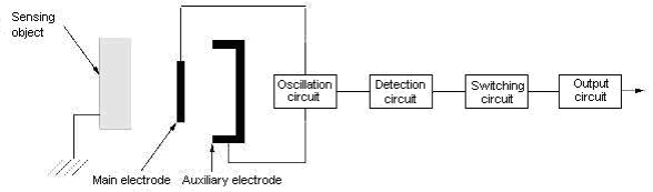
When the metal or the dielectric approaches the electrode, the capacitance between a main electrode and ground potential increases by the effect of the electrostatic induction.
The CR oscillation circuit that starts oscillation depending on the capacitance change of this electrode is composed, and the approach of the sensing object is detected by increase of the oscillation amplitude.
When the sensing object is the dielectric, the change in the capacitance between a main electrode and ground potential grows by the relative permittivity large and it is easy for the sensor to detect it.
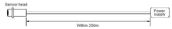
Is it possible to extend the cable of the Proximity Sensor?
Yes, it provides as follows in each type of the sensor.
The following occur.
Voltage descent by resistance component of cable
Extension of rise time of output waveform by the capacity between lines of cable
Therefore, please use the cable more than the same nominal cross-sectional area and make the length of the cable to the power supply within 200m.
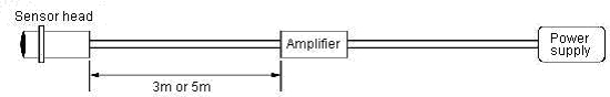
The capacity between lines of the cable changes when the cable length between the sensor and the amplifier is changed, the oscillation frequency is changed, and the characteristic change in the sensing distance and the temperature characteristic occurs.
Therefore, it is not warrantable that the cable length between the sensor and the amplifier is made outside regulations.
Moreover, it is not warrantable that processing it to the cable like the extension by the customer even if it is in regulations.
The capacity between lines of the cable changes when the cable length between the sensor and the amplifier is changed, the oscillation frequency is changed, and the characteristic change in the sensing distance, the temperature characteristic and linear output occurs.
Therefore, the cable length between the sensor and the amplifier is 3m or 5m. Please specify the cable length with the selector of the amplifier side.
What is the principle of operation of Long-distance Proximity Sensor the TL-L Series?
The circuit composition and the principle of operation are as follows.
It is called the differential coil type. It has the exciting coil that the high frequency oscillates and a couple of detector coil with which the differential is united, only the magnetic field by eddy current caused when metal approaches is detected.
Though the long distance can be detected, outline is large because there are a lot of coils.
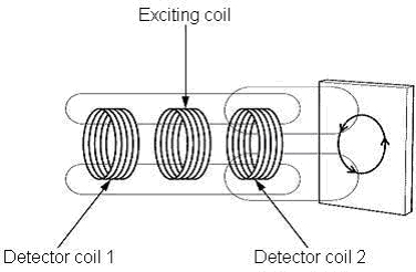
(1) 'Magnetic field by the exciting coil' is caused by the exciting coil at the center in a right and left detector coil.
(2) 'Eddy current magnetic field' is caused in a detector coil 2 by generating the eddy current on the surface of the sensing object when the sensing object approaches.
Detector coil 1:
Only 'Magnetic field by the exciting coil'
Detector coil 2:
Magnetic field by the exciting coil' and 'Eddy current magnetic field'
(3) The magnetic field of each detector coil is converted into the induction voltage.
Detector coil 1:
Only 'Induction voltage by the exciting coil'
Detector coil 2:
Induction voltage by the exciting coil' and 'Induction voltage by the eddy current magnetic field'
(4) It judges it from the value in which the voltage of detector coil 1 is subtracted from the voltage of detector coil 2 to judge the presence of the sensing object.
When there is a detection object:
Difference between coil 1 and coil 2= 'Induction voltage by the eddy current magnetic field'
When there is no detection object:
Difference between coil 1 and coil 2= none
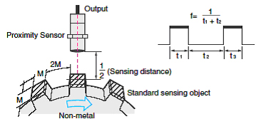
What is "Response frequency"?
When the sensing object moves at high speed and it passes continuously, the response of proximity sensor is important.
The response of proximity sensor is defined by response frequency and response time, please confirm satisfaction for movement speed or interval of sensing object.
The maximum number of detection repetitions that can be output per second when the standard sensing object is repeatedly brought into proximity.
See the accompanying diagram for the measuring method.
What Proximity Sensors are available for applications that require heat resistance?
E2C-H Series of Heat-resistant Proximity Sensors is available. Normal Proximity Sensors have an ambient operating temperature range of -25 to 70°C. E2C-H Series has an ambient operating temperature range of -10 to 200°C.
E2C-H Series has the following characteristics:
These Sensors, however, are not filled internally with resin, and so the degree of protection is reduced.
What malfunction occurs in the Proximity Sensor because of the influence of a surrounding metal?
The sensing distance is extended, and faulty reset is resulted.
ON point (ON2) when there is a surrounding metal is further than ON point (ON1) when there is no surrounding metal.
There is no OFF point because it lowers more than OFF judgment level even when the sensing object is far and the oscillation level is high when there is a surrounding metal.
There is a possibility of taking the influence of the noise by various pathways in the proximity sensor, and the malfunction mode changes depending on the frequency band and the level of the noise.
Typical examples of the malfunction are as follows;
(1) Output chattering
(2) It remains the state when the sensor detects the object regardless of the presence of the sensing object.
(2) It remains the state when the sensor detects the object regardless of the presence of the sensing object.
(1) Occurrence frequency
(2) The malfunction mode
(3) Is all numbers generated?
(4) Is not there environmental influence?
(1) To identify of which pathway noise it is.
(2) Is there relation between operation of specific equipment and the malfunction of the sensor?
(1) The power equipment and frame ground of the control equipment are surely grounded.
(1) It wires the power line away from the signal line (wiring for the sensor).
(2) Please examine the following measures.
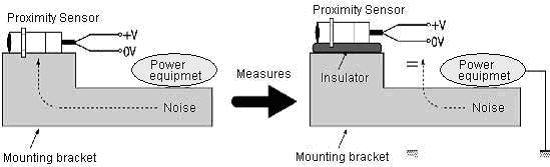
1) The inverter motor and the mounting metal are grounded.
2) The noise source and the power supply (0V) are grounded with the capacitor.
3) Insulators such as rubbers and resins are put between the sensor and the mounting (metal).
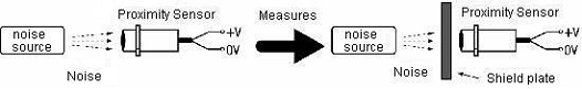
1) The shield plate is put between the sensor and the noise source (switching power supply).
2) The setting distance of the sensor is separated from the noise source to the place without the influence.
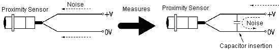
1) The capacitor, the noise filter and the varistor are put between power supply lines (between + V and 0V).
Please teach the principle of operation of Anti-aluminum cut chips model cylinder type Proximity Sensor the E2EZ Series.
The circuit composition and the principle of operation are as follows.
 2. Principle of operation
The aluminum chips with small density are not detected, and the detection only of the sensing object is enabled by setting the oscillation frequency lower than usually though it is the same circuit composition as high frequency oscillation type such as the E2E Series.
There are characteristics that the eddy current caused in the sensing object concentrates on the surface of the sensing object (skin effect). The lower the frequency of the high frequency magnetic field (oscillating frequency) is, the deeper the depth that the eddy current flows (epidermal depth) is by the high frequency magnetic field from the proximity sensor.
By using this, the epidermal depth of the eddy current is deepened and the influence is reduced (the magnetic flux is penetrated) by lowering the oscillating frequency of the sensor, the aluminum chip is penetrated and the sensing object is detected.
Is it possible to use the Proximity Sensor near the magnetic field (magnet)?
It is possible to use it.
Because the core is not used, the influence of the magnetic field is not received.
If DC/AC magnetic field is 200G or less on the sensing surface of sensor, it is possible to use it.
The proximity sensor cannot oscillate and turns on when using it in the environment where 200G or more magnetic field is generated.
The sensing distance extends when the proximity sensor does not turn on, and there is a possibility that faulty reset and turning on are generated by the environmental temperature change.
What is "Response time"?
When the sensing object moves at high speed and it passes continuously, the response of proximity sensor is important.
The response of proximity sensor is defined by response frequency and response time, please confirm satisfaction for movement speed or interval of sensing object.
The response of proximity sensor is defined by response frequency and response time, please confirm satisfaction for movement speed or interval of sensing object.
OFF delay time: the time from non detection of the sensing object to turning off
Generally, the ratio is as follows because of the circuit.
ON delay time : OFF delay time = 1 : 2
Response time is estimate by response frequency.
Actual ON delay time and OFF delay time is shorter than estimated time.
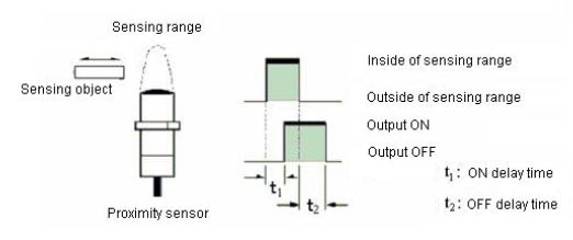
t1: ON delay time (ms) = 1 ⁄ Response frequency (kHz) x (ON delay ratio)⁄(ON delay ratio + OFF delay ratio)
t2: OFF delay time (ms) =1⁄ Response frequency (kHz) x (OFF delay ratio)⁄ (ON delay ratio + OFF delay ratio)
t1: ON delay time (ms) =1/1 x ( 1 )/ ( 1+2) = 0.3ms
t2: OFF delay time (ms) =1/1 x ( 2 )/ (1+2)=0.7 ms
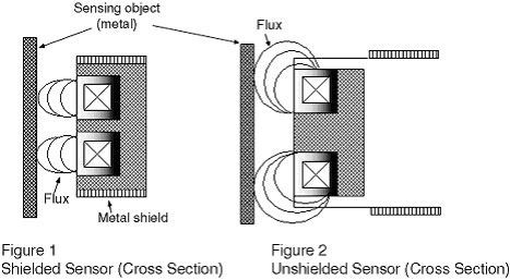
Why is there a difference in the effect of surrounding metal between Shielded Proximity Sensors and Unshielded Proximity Sensors?
As shown in Figure 1, the surface of the detection coil on Shielded Proximity Sensors is covered with metal, so the flux is concentrated at the front of Sensors, which reduces the influence of surrounding metal.
As shown in Figure 2, the surface of the sensing coil on Unshielded Proximity Sensors is not covered with metal, so flux is also generated from the surface, which makes Sensors easily influenced by surrounding metal.
Can General-purpose Proximity Sensors be used as the connection switch of F92A Inductive Couplers?
Yes, it can be used if the output circuit of Sensors are an open collector
1.NPN Open Collector
Connect Sensors output terminal and the negative terminal to the switch connection terminals of F92A.
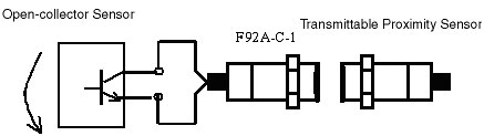
2.PNP Open Collector
Connect Sensors output terminal and the positive terminal to the switch connection terminals of F92A.
In this case, however, the transmission distance will be approximately half the distance when a contact switch is used.
If contacts are used for the connection switch, current to F92A will flow in both directions, as shown by the arrows in Figure 1. If a Sensor with an open-collector output is used, current will flow to F92A in one direction, as shown in Figure 2, and so the change in impedance input to Proximity Sensors will be reduced by half. To obtain the same change in impedance as when using a contact switch, the transmission distance between Proximity Sensors and F92A will need to be reduced by half.
Figure 1
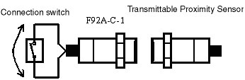
Figure 2
What is the allowable bending radius of coaxial cables or shielded cables for Photoelectric Sensors and Proximity Sensors?
A minimum bending radius of five times cables diameter is recommended for coaxial cables and shielded cables.
Note:The minimum bending radius given above is the same for coaxial and shielded robot cables.
Reference Information:
For a standard cable, a minimum bending radius of three times cables diameter is recommended.
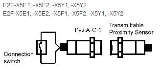
Why is it not possible to use Proximity Sensors that are not listed in the catalog as Transmittable Proximity Sensors for F92A Inductive Couplers?
Proximity Sensors that are not described as Transmittable Proximity Sensors have different oscillating frequencies and oscillation methods, and cannot be used because they are inappropriate for transmissions with F92A.
The following Proximity Sensors are transmittable.
Can a Capacitive Sensor detect charged objects?
Yes, but the sensing distance depends on the charged object and the amount of charge. If the object is charged, the electrostatic capacitance will also change when the status of the electrical load is changed, and so stable detection cannot be performed. For stable detection, it is recommended to first ionize the object.
What is the current consumption for 2-wire DC Proximity Sensors?
For 2-wire DC Proximity Sensors, the current consumption is the same as the leakage current. The current consumption is 0.8 mA max. for the E2E-X[]D[] 2-wire DC Proximity Sensors.
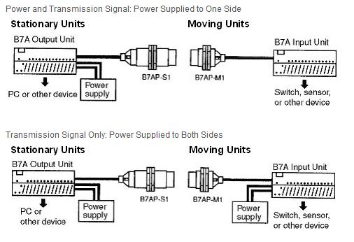
How many 2-wire DC Proximity Sensors can be connected to the input side of B7AP Power Couplers?
1.Power Supplied to One Side
Up to ten Sensors can be connected if power is supplied only to B7AP-S1 (Stationary Units).
1-1. Connect B7A Input Unit to the B7AP-M1 (Moving Units).
Output current from Moving Unit: 38 mA (output voltage: 12 VDC)
Input current per B7A Input Unit: 3.8 mA
Given the conditions above, up to ten inputs can be used.
1-2. The output current of 38 mA from Moving Units do not include the current consumed for B7A Input Units itself.
2.Power Supplied to Both Sides
Up to 16 Sensors can be connected if power is supplied to both sides of the B7AP-S1 and B7AP-M1. In this case, a 2-wire AC Sensor or Programmable Controllers can also be connected.
 Automation Systems
  Motion & Power Solutions
  Safety, Vision and IDENT
  Sensing Solutions
  Control Components
  Switching & Accessories
  Switchgear and Trolley Systems
  Process Weighing
  LED Lighting
  Omron
Omron
 Mitsubishi
 Delta
Delta
 Autonics
 Inno
Inno
 Honeywell
 Novotechnik
 Orientalmotor
 Microscan
 IPA
IPA
 Technomech
 Intech
 IOT & Traceability
 Project & Panel Engg.
 Application Case Studies
 Solutions by Industry
 Solutions by Process
 Solutions by Product
 Corporate Information
 Company Profile
 Quality Policy
 Mission Statement
 Chairman's Message
 Intech Group Companies
