Frequently asked questions and answers for Rotary Encoders - Industrial Automation
What is the method that connects Rotary Encoder of phase difference output type (Phase A and Phase B output) to counter and adds at the reverse rotation?
For the reverse rotation, please wire the Phase A and Phase B outputs reversely.
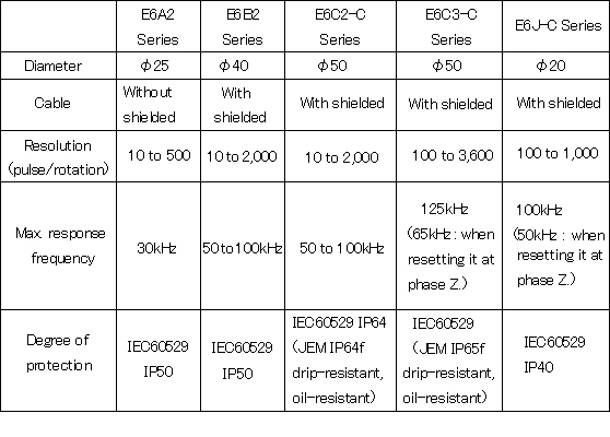
What is the main difference among the E6A2, E6B2, E6C2-C, E6C3-C and E6J-C Series of incremental Rotary Encoder?
The main difference points are as follows.
What is the feature of the Gray code?
Because only one bit of all codes change when the code changes and it is unnecessary to match the reading timing in the gray code, it can be read steady compared with other code (the binary code and the BCD code).
The binary code and the BCD code need the one bit strobe signal that takes timing to prevent the reading mistake, therefore a lot of one connecting wires are necessary for resolution.
e.g.
* The Gray code change only 1 bit, the binary code change 5 bit.
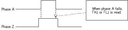
What timing is pulse signal of phase Z output?
Phase Z outputs signal only once per a rotation.
We recommend using to make phase A and phase Z serial, to take timing with rising or falling of phase A to improve accuracy.
What is "Absolute code"?
A pure binary code, expressed in the format 2n.
Multiple bits may change when an address changes.
A code in which only one bit changes when an address changes.
The code plate of the Rotary Encoder uses gray code.
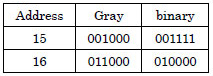
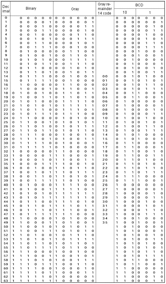
This code is used when expressing resolutions with gray code that are not 2n, such as 36, 360, and 720. The nature of gray code is such that when the most significant bit of the code changes from 0 to 1 and the same size of area is used for both the larger value and the smaller value of objects, the signal only changes by 1 bit within this range when changing from the end to the beginning of a code.
This enables any resolution that is an even number to be set with gray code. In this case, the code does not begin from 0, but from an intermediate code, and thus when actually using a code it must first be shifted so that it starts from 0.
The example in the code table shows 36 divisions. For the change from address 31 to 32, the code extends from address 14 to 49 when 18 addresses each are taken for the objects. When changing from address 49 to 14, only one bit changes, and we can see that the characteristic of gray code is preserved. By shifting the code 14 addresses, it can be converted to a code that starts from address 0.
Binary Coded Decimal Code.
Each digit of a decimal number is expressed using a binary value.
Absolute code table is as follows.
What is "Resolution"?
The pulse count of an incremental signal output when the shaft revolves once, or the absolute address count.
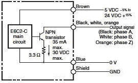
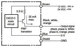
What is "Output circuit"?
An output circuit where the emitter of the output circuit transistoris the common and the collector is open.
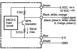
An output circuit where the emitter of the output circuit transistor is the common and a resistor is inserted between the collector and the power supply to convert the output from the collector to a voltage.
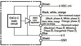
An output method that uses a special IC for high-speed, long-distance data transmission that complies with the RS-422A standard.
The signal is output as a differential secondary signal, and thus is strong with respect to noise.
A special IC called a line receiver is used to receive the signal output from a line driver.
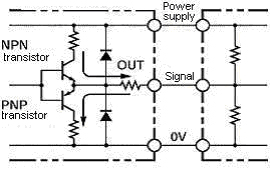
An output circuit with two output transistors (NPN and PNP) on the output.
These two output transistors alternately turn ON and OFF depending on the high or low output signal. When using them, pull up to the positive power supply voltage level or pull down to 0 V.
The complementary output allows flow-in or flow-out of the output current and thus the rising and falling speeds of signals are fast.
This allows a long cable distance.
They can be connected to open-collector input devices (NPN, PNP).
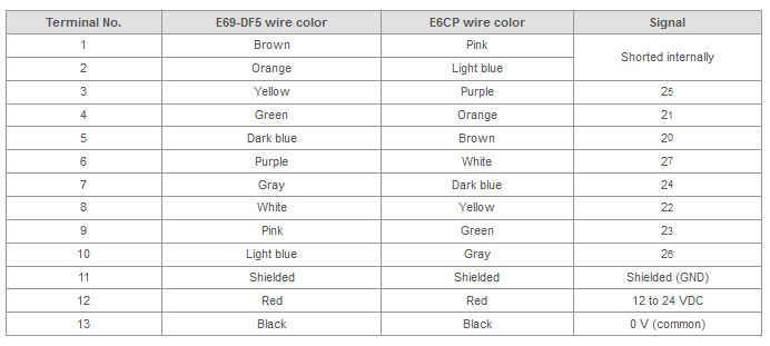
What are the lead wire colors and signals for E6CP-AG5C-C/E69-DF5 Rotary Encoders?
The lead wire colors and signals are given in the following table.
Can regular lead wire be added in the middle of E69-DF[] Extension Cables when it is connected to E6[][] Absolute Encoders and H8P[] Cam Positionesr?
Trouble will occur in the sense that the rated specifications will not be met. To reduce the effects of noise, use a special E69-DF[] Extension Cable. Do not relay the cable using a terminal block. Doing so will cause the signal to be easily affected by other signal lines.
Applicable model combinations:
E6CP-AG5C-C/H8PS
E6C3-AG5C-C/H8PS
E6F-AG5C-C/H8PS
E6F-AB3C-C/H8PR
How many meters of the cable of the Rotary Encoder are extended?
Voltage output and open collector output type are 10m, complementary output type is 30m, and line driver output type is 100m.
However, when the cable length is extended, it is necessary to confirm use conditions in the case of the voltage output and the open collector output type. Because the output waveform startup time is lengthened, the response frequency lower, it affects the phase difference characteristics of phases A and B, and the output residual voltage increases
Please use the cable of the same kind (conductor cross section and shielded or unshielded) when the cable length is extended.
The recommended cable of line driver output type is the TKVVBS4P-02T that is twisted-pair cable made in TACHII ELECTRIC WIRE CO., LTD..
The twisted-pair cable is a suitable structure for the transmission of RS-422A signals, and has the characteristic which denies the electromotive force is generated in the wire by twisting two outputs and takes off the noise component.
Purchase is possible in 100m.
What is the difference between single-turn absolute Rotary Encoder and multi-turn absolute Rotary Encoder?
Single-turn absolute rotary encoder is absolute position detection within one rotation to which the rotation angle is output in parallel as an absolute numerical value by the code of 2n, the position of the accumulation is not understood when rotating by two rotations or more.
Multi-turn absolute rotary encoder understands the position of the accumulation. A detection part of Multi-turn absolute is basically the same structure as single-turn absolute.
A part of an absolute signal of one rotation is used and the amount of the rotation is counted once a rotation by the counter installed internally, multi-turn data is output as an absolute code.
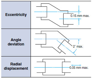
What happens if a coupling is not used?
If a coupling is not used, the rotating (i.e., drive) shaft cannot be conveyed to the Rotary Encoder. A coupling can relax the load on the shaft to the Rotary Encoder if there is eccentricity, declination, or deviation in the shaft direction. A coupling is thus required to extend the life of the bearings, i.e., the mechanical life.
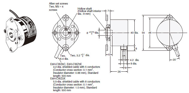
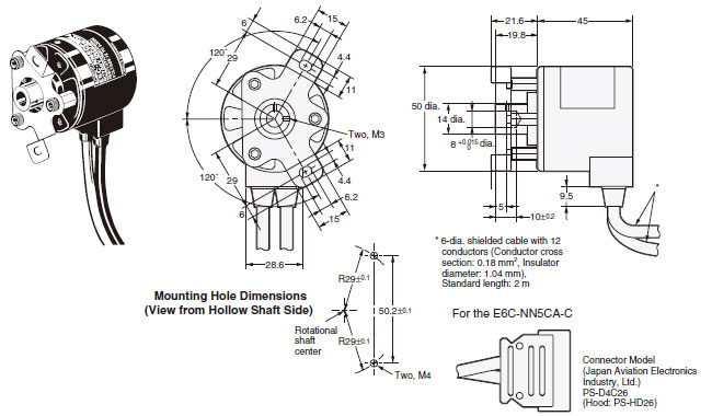
As shown in the following figure, E6H and E6C-NN5CA Rotary Encoders have hollow shafts, do not require a coupling (because the coupling is built in), and therefore reduce the installation space.
Can the origin (phase "Z") be positioned with only the Rotary Encoder (without seeing ON/OFF of the output)?
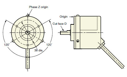
1. In the E6B2-C and E6C2-CWZ[][], positioning the origin is almost possible by setting phase "Z" origin to cut face "D". (within ±20°)
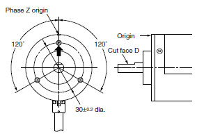
2. In the E6C3-CWZ[][]H, positioning the origin is almost possible by making cut face "D" of the shaft and the direction of drawing out of the cable as the following figure. (within ±15°)
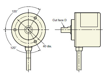
3. Please confirm ON point of phase "Z" output on the controller side and adjust the origin so cut face "D" and phase "Z" origin of other models are not suitable.
What is the factor to miscount the output pulse of the incremental Rotary Encoder?
Please reduce the influence of the noise.
Please keep wiring as far away from single piping and the noise source (inverter motor) as possible.
We recommend combining both phase A and phase B with the addition and subtraction counter because it can cancel the wrong pulse by the phase difference output.
Please defend the mounting procedure of the rotary encoder and notes of the mounting, and confirm whether coupling is correctly mounted or the transmission system doesn't run idle.
What is "Maximum response frequency"?
What are the precautions for mounting Rotary Encoders?

What is the method of confirming abnormalities of the number of output pulse (omission of the number of pulse) in the incremental rotary encoder?
It is possible to judge it by counting the number of pulse signals from phase Z signal to the next phase Z signal if there is phase Z output.
Moreover, it is possible to judge it by counting the number of pulse signals when the axis is made one rotation after a standard position somewhere is made to be understood in the axis and the chassis if there is no phase Z output.
What is "Electric response rotation"?
Electric response rotation(r/min) = Maximum response frequency ⁄ Resolution
It is the rotation at which the signal can respond.
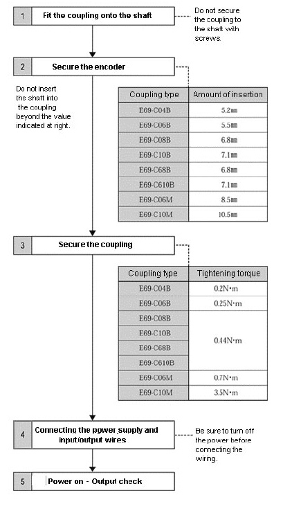
How to mount the Rotary Encoder?
The mounting procedures are as follow;
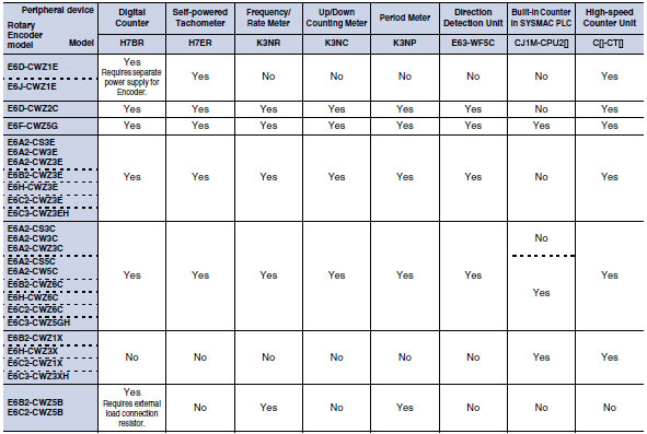
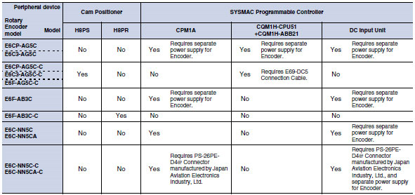
What are peripherals that can be connected with the Rotary Encoder?
Please refer to the following table of possibility of connection.
Yes: Possible
No: Impossible
What is the difference between incremental Rotary Encoder and absolute Rotary Encoder?
Incremental rotary encoder outputs the pulse corresponding to the rotation angle only while rotating, and is the counting measurement method that adds up the pulse from the measurement beginning point
Absolute rotary encoder outputs the signal of position corresponding to the rotation angle by code. The Absolute position from the starting point is measured by the output code data. The position is memorized though the power supply is cut off.
What is the factor to misread the output data of the absolute Rotary Encoder?
Please reduce the influence of the noise.
Please keep wiring as far away from single piping and the noise source (inverter motor) as possible.
We recommend the rotary encoder with the strobe signal that informs of reading timing.
Or please use the Gray code type instead of the binary code and the BCD code
Please annul this data and read it again as measures on the receiver side when the reading data changes greatly compared with last time.
Please defend the mounting procedure of the rotary encoder and notes of the mounting, and confirm whether coupling is correctly mounted or the transmission system doesn't run idle.
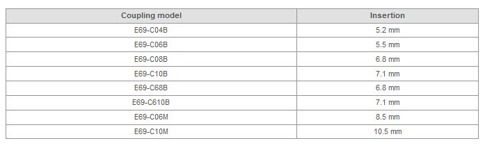
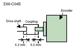
How far should the shaft be inserted into the coupling?
The hollow section (corniced part) near the center of the coupling absorbs vibration and prevents Rotary Encoders becoming damaged due to vibration. To protect Rotary Encoders from vibration, insert the shaft into the coupling at least to the length given in the following table.
 Automation Systems
  Motion & Power Solutions
  Safety, Vision and IDENT
  Sensing Solutions
  Control Components
  Switching & Accessories
  Switchgear and Trolley Systems
  Process Weighing
  LED Lighting
  Omron
Omron
 Mitsubishi
 Delta
Delta
 Autonics
 Inno
Inno
 Honeywell
 Novotechnik
 Orientalmotor
 Microscan
 IPA
IPA
 Technomech
 Intech
 IOT & Traceability
 Project & Panel Engg.
 Application Case Studies
 Solutions by Industry
 Solutions by Process
 Solutions by Product
 Corporate Information
 Company Profile
 Quality Policy
 Mission Statement
 Chairman's Message
 Intech Group Companies
