Frequently asked questions and answers for Safety Relays - Industrial Automation
What is an inverse input?
An inverse input is an input that creates a potential difference between two input circuit channels (one input positive and one input negative potential) to ensure that the power is cut and the safety function operates if the wiring is damaged and a short-circuit occurs between the channels.
Why is the Safety Relay required for safety circuits?
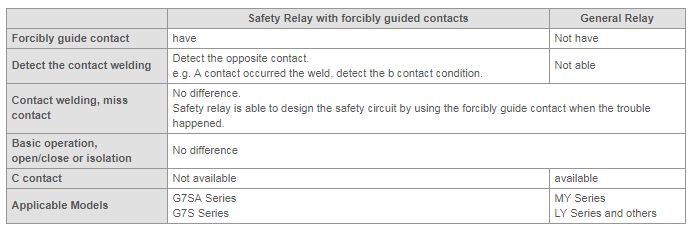
The Safety Relay is provided with a forcibly-guided contact mechanism which prevents the contact point a and the contact point b from being in operating states simultaneously when being welded, and can detect contact welding in the Safety Relay itself. It is possible to design safety circuits by using this function.
The General Relay is not provided with this forcibly-guided contact mechanism.
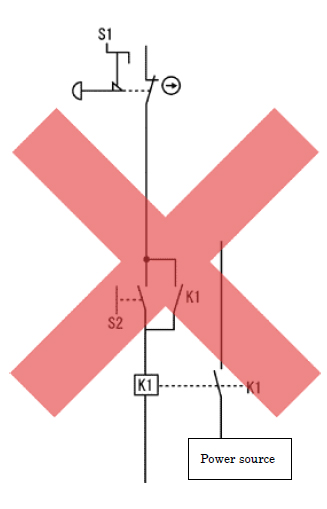
However, be aware that incorrect circuit design may cause the Safety Relay to be dangerous. For example, the circuit shown in the Fig-1 cannot cut off the power, and thus results in dangerous situation.
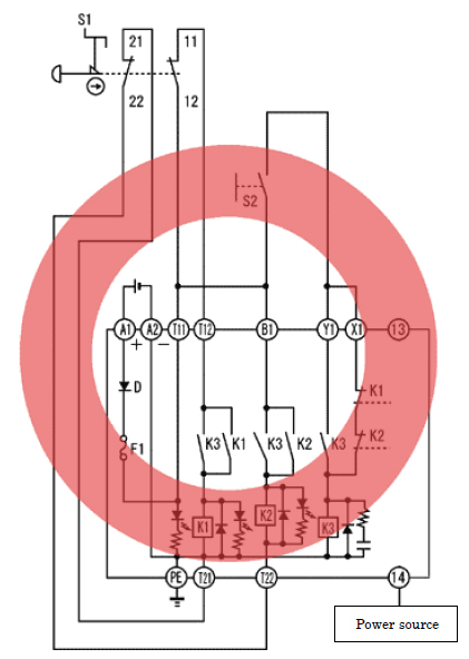
As shown in the Fig. 2, design the circuit with redundancy and configure a self-monitoring function adopting the welding check function of the forcibly-guided contact mechanism.
For what purpose is the Safety Relay Unit provided with a feedback circuit?
For example, a feedback circuit is employed to detect welding of the contact point of the contactor which drives motors.
In this case, even if the contact point is welded, the Safety Relay Unit does not restart thanks to this circuit, thus ensuring safety.
However, be sure to use double contactors.
What is the difference between an auto reset and manual reset?
An auto reset is when there is no reset switch in the feedback circuit and the device automatically starts when an input turns ON.
A manual reset is when there is a reset switch in the feedback circuit and the device does not start when the input turns ON unless the reset switch is pressed.
A manual reset is used for machines that people can enter and for emergency stop circuits, and an auto reset is used for machines that people cannot enter. Resets must occur only after all hazards have been cleared and a manual reset is basically safer. Auto resets can be used for guards through which people cannot enter. Always use manual resets for guards through which people can enter and emergency stops.
Caution!
G9S-2001/2002 Safety Relay Units
G9SB-2002-A Safety Relay Units
G9SB-200-B Safety Relay Units
G9SB-3012-A Safety Relay Units
G9SB-301-B Safety Relay Units
A manual reset cannot be used for the above models. Never use a manual reset with these models because sometimes danger cannot be avoided if a manual reset is used.
The same applies to using a manual reset for G9SA Safety Relay Units in Auto Reset Mode: Never use manual mode.
Why are two inputs required for the Safety Relay Unit?
European standards EN954-1 category 3 and 4 require that a single fault in any parts of the unit does not lead to a loss of the safety function. For this reason, the Safety Relay Unit requires two inputs.
What is the difference between the Safety Relay and the Safety Relay Unit?
Of course, safety circuits can be designed by using the Safety Relay. However, a reciprocal check of redundant circuits is required.
Meanwhile, the Safety Relay Unit is a block of circuits which combines the Safety Relay with other components in order for the safety circuit to be easily designed.
What is a positive common input?
It is an input mode where there are two inputs and both of them are connected to the positive side of the power supply. Both inputs will be at the same voltage, so if there is a short circuit between two terminals, it will not be detected.
If there is the possibility of a short circuit at the input, do not use this input method because it cannot detect faults, and it cannot ensure safe operation.
What is the difference between the Safety Relay and the General Relay?
Why cannot Programmable Controller (PLC) or Programmable Terminal (PT) be used for safety circuits?
Industrial standards IEC60204-1(JIS B 9960-1) prescribes that the safety circuit should not be configured only with the Programmable Controller.
This comes from the general requirements of the IEC60204-1(JIS B 9960-1) that safety-related functions should be configured with the verified circuit technologies and components.
However, since circuits depending on the movement of programmable electronic devices may sometimes not fulfill these requirements, for this reason, Programmable Controller or Programmable Terminal cannot be used for safety circuits.
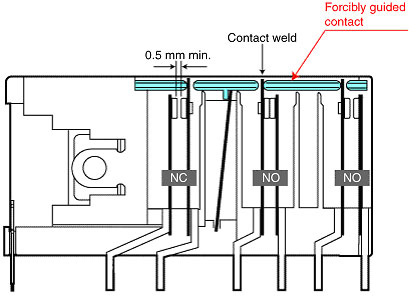
How does a forcibly guided contact work?
If an NO contact becomes welded, all NC contacts will maintain a minimum distance of 0.5 mm when the coil is not energized. Likewise if an NC contact becomes welded, all NO contacts will maintain a minimum distance of 0.5 mm when the coil is energized
Refer to the following diagram.
The forcibly guided contact mechanism is a requirement of EN 50205 for Safety Relays.
Class A Safety Relays (i.e., all contacts are forcibly guided contacts) have the mark(*) on the nameplate.

Forcibly Guided Contact Mechanism (G7SA Safety Relays)
Can an NPN Safety Light Curtain be connected to F3SP-B1P Control Unit?
No, an NPN output cannot be connected. Only a PNP output can be connected.
 Automation Systems
  Motion & Power Solutions
  Safety, Vision and IDENT
  Sensing Solutions
  Control Components
  Switching & Accessories
  Switchgear and Trolley Systems
  Process Weighing
  LED Lighting
  Omron
Omron
 Mitsubishi
 Delta
Delta
 Autonics
 Inno
Inno
 Honeywell
 Novotechnik
 Orientalmotor
 Microscan
 IPA
IPA
 Technomech
 Intech
 IOT & Traceability
 Project & Panel Engg.
 Application Case Studies
 Solutions by Industry
 Solutions by Process
 Solutions by Product
 Corporate Information
 Company Profile
 Quality Policy
 Mission Statement
 Chairman's Message
 Intech Group Companies
