Frequently asked questions and answers for Servomotors, Servo Drivers - Industrial Automation
What is the cause of the E23 error in an R88D-HT10 Servo Driver?
The 23 error occurs when there is an open phase in the main circuit. An error is detected when a low voltage was detected in the main circuit's input section and lasted longer than 50 ms.
The likely causes of the error are that the main voltage power supply is not being input or there is an open phase in the main circuit. In general, this error is caused by a problem to the power supply input section. Check the main circuit power supply wiring.
Are there any Servomotors that have countermeasures against harmonics?
The W-series Servomotors have countermeasures against harmonics.
The W-series Servomotors are equipped with a terminal connection for a DC Reactor, so a DC Reactor can be connected.
OMRON offers Reactors to control harmonics in other Servomotors besides the W-series Servomotors. AC Reactors for Inverters can be used with the Servomotors above.
OMRON AC Reactors for Inverters are listed below, so use the corresponding AC Reactor.
Connect one Reactor per Servo Driver
| Servo Driver model | R88D-UP04V: | R88D-UP08V: |
| Reactor model | 3G3IV-PUZBAB2.5A4.2MH | 3G3IV-PUZBAB5A2.1MH |
Is there a cable with attached connectors available for the R88D-U Servo Driver's analog monitor output?
Yes, there is a cable available. The Analog Monitor Cable for the W-series (R88D-W) Servo Drivers can be used. The Cable's model number is R88A-CMW001S.
When a 3F88L-132 Cam Positioner is replaced with a 3F88L-160 Cam Positioner, can the 3F88L-DP30 RPM Display Unit be used as-is?
The Cam Output Cable, I/O Terminal, and Resolver can be used as-is, but the Display Unit cannot be used.
The M7E and M7F Digital Display Units are available separately for use as displays.
What shape of motor shaft should be selected if a Reduction Gear is installed on a SMARTSTEP A-series Servomotor?
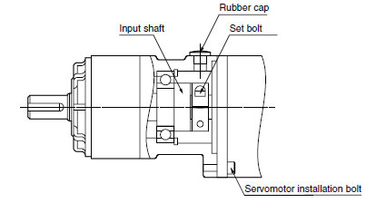
Installation
Use a Servomotor with a straight shaft and without a key when installing reduction gears.
Use only the specified combinations of Servomotors and reduction gears. Using a combination that is not specified, or using in combination with another company's reductions gears or Servomotor may result in a reduction in the service life of the motor bearings.
The dimensions of the Servomotor mounting flange on the reduction gears differ for each Servomotor. Do not install reduction gears on a Servomotor other than the one specified.
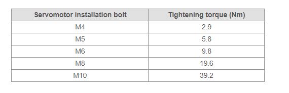
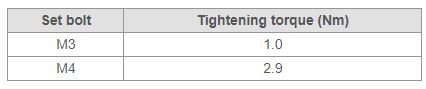
Install reduction gears on the Servomotor using the following procedure.
Using Reduction Gears from Other Companies (Reference Information)
If the system configuration requires that a SMARTSTEP A-series Motor be used in combination with a reduction gear from another company, select the reduction gear so that the loads on the motor shaft (i.e., both the radial and thrust loads) are with the allowable values. Also, control the motor speed and output torque so that the allowable input speed and allowable input torque of the reduction gear is not exceeded
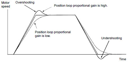
What is the procedure for manually adjusting gain when using a Servomotor?
Perform the following procedures to adjust the gain.
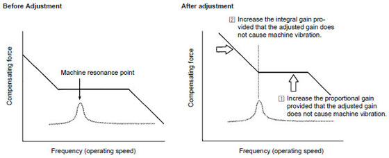
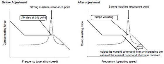
Generally, basic adjustments can be performed using only proportional and integral gain, but vibration may not stop depending on the mechanical system or positioning may be delayed because the gain is low even if the vibration does stop. If this occurs, adjust the current loop filter time constant.
This adjustment is used with a pulse train input. It is not relevant to an analog input.
The following graph shows how the response of the servo system (i.e., frequency characteristics) changes when the speed loop gain and adjustment parameters are changed.
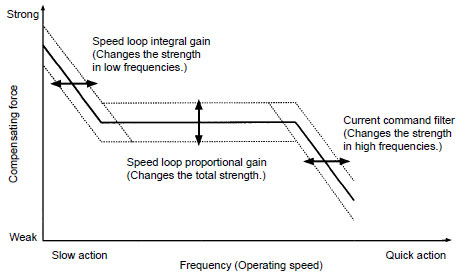
In this graph, the horizontal axis represents the frequency (i.e., movement speed) and the vertical axis represents the strength of the corrective ability (i.e., the ability to have error approach zero).
This adjustment is effective when there is mechanical system resonance and adjustment cannot be performed using only speed loop proportional gain or integral gain.
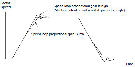
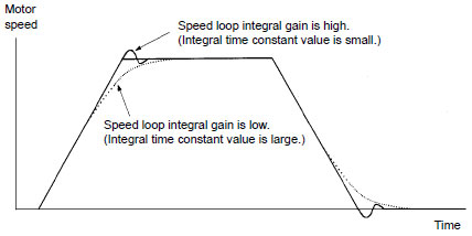
The following figure shows the servo system response (time axis) when the speed loop gain and the adjustment parameters are changed.
What concepts are applied for countermeasures for noise for a Servo System?
The following four aspects are important when considering countermeasures for noise.
Devices that cause rapid changes in voltage or current are noise sources.
Generally the larger the signal power, the stronger the noise source becomes.
List the noise sources that surround your Servo System.
Once you know the source, position, type, and characteristic of the noise, you can narrow down the noise transmission paths. For each possible noise transmission path, apply a countermeasure. Start with the most probable path. You can narrow down the noise transmission path by seeing how effective the countermeasure is.
Another method is to use shield boards connected to frame grounds to check the effect of electromagnetic waves, electromagnetic induction, and electrostatic coupling.
Even if the countermeasure applied to a noise transmission path was ineffective, do not remove the countermeasure. There may be several noise transmission paths and the countermeasure that you applied may be blocking the second largest noise path.
Leakage current from the motor electrostatic coupling to the frame ground becomes large in Servo Systems and Inverters.
If the current is not absorbed very well, the frame ground potential will become unstable. This increases cases where noise is transmitted to other devices through the frame ground.
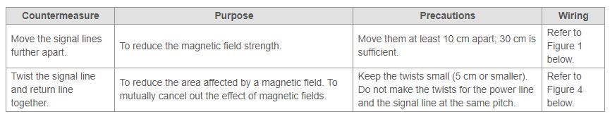
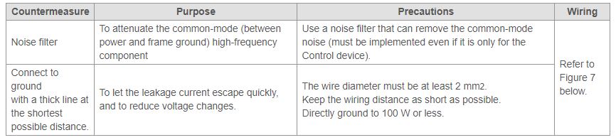
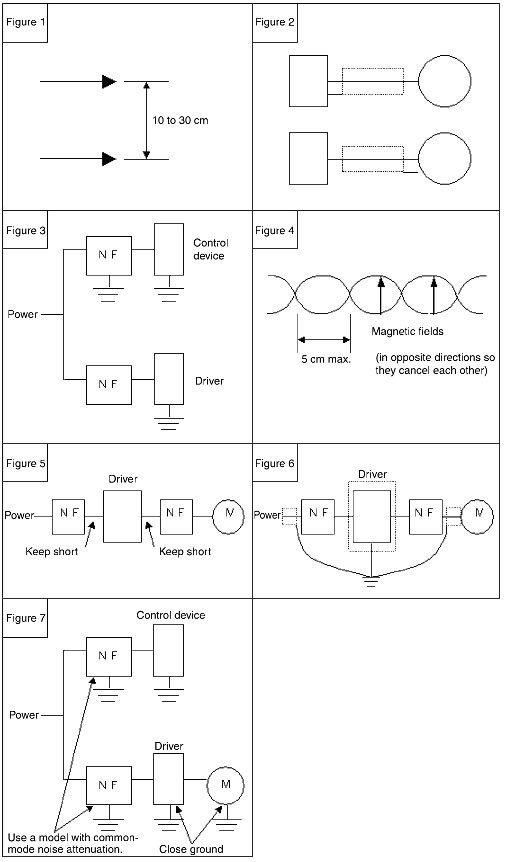
Countermeasures for noise transmission paths as well as countermeasures against leakage current are described below.

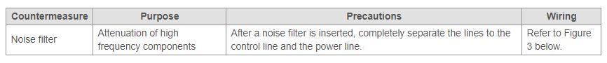
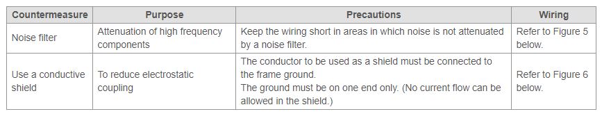
Note:Use a noise filter for an output without a capacitor for the noise filter on the driver output side.
If noise-related errors persist even after applying noise countermeasures, try the following measures. They may be effective depending on the model of Position Controller and Servo Driver.
Noise is superimposed on the command pulse input signal, so the Driver takes the noise as a command signal.
Separate the power source.
Use a dedicated power supply for the Controller's pulse output.
It is effective to separate the ground line as well.
Shield the pulse signal.
If positioning is offset even after separating the power source, connect both ends of the command pulse signal line shield (shielded twisted-pair cable) to the frame ground.
Note:
Make sure that the Controller and the Driver are always grounded to 100 Ω or less.
If the grounding is ineffective, it will make the problems worse.
Noise is superimposed on the feedback pulse (encoder signal), so the Controller takes the noise as a feedback pulse.
Countermeasures:Shield the feedback pulse signal.
Connect both ends (Controller and Driver) of the feedback pulse signal shield (shielded twisted-pair shielded cable) to the frame ground.
Note: Make sure that the Controller and the Driver are always grounded to 100 Ω or less. If the grounding is ineffective, it will make the problems worse.
If the ground to 100 Ω is bad, noise will be transmitted from ground. If noise persists no matter what countermeasures are used, check the ground potential.
Connect to a good ground at 100 Ω or less.
Improve the condition of the ground.
Separate the frame ground of high-power devices and low-power devices.
Float the frame ground line of the Control device and other applicable devices
Cut the shield of the shielded cable.
These countermeasures are for worst case scenarios. If the Servo System is operating in an environment with serious noise problems, it will not operate at full capacity.
What models of Servomotors with decelerators are used with SMARTSTEP A-series Servo Drivers?
The Decelerator and Motor for the SMARTSTEP are separate devices. You must attach the Decelerator (sold separately) to a Servomotor with a straight shaft without a key.
Note:The Decelerator used to come attached with the motor, but the SMARTSTEP treats them as separate devices. The Decelerator must be attached by the customer.
What models of Servomotors with decelerators are used with SMARTSTEP A-series Servo Drivers?
Noise is an unexpected random signal. Some noise originates from natural phenomena, such as lightening, but most noise that actually affects the operation of a device is created artificially inside or external to the device. Think of noise as an artificially created signal that travels through a transmission path to another signal line.
Noise Sources
Devices that cause rapid changes in voltage or current are noise sources.
The more rapid the changes, the higher the voltage, and the higher the current, the stronger the noise source becomes.
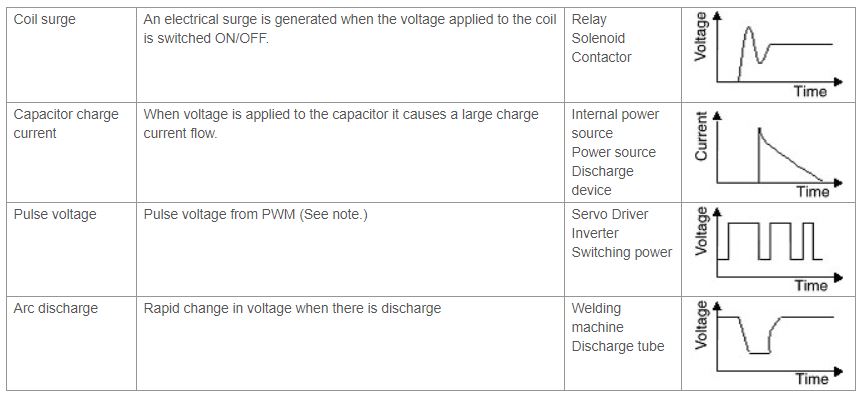
Note:PWM (pulse width modulation) is a method used to alter the voltage. By switching the voltage ON/OFF at a fast switching frequency, the average voltage can be modified.
3. Transmission Path of NoiseThere are the following four noise transmission paths.
Is there a Servo System that has full-closed control?
Full-closed control is possible by installing a DeviceNet Communications Unit (R88A-NCW152-DRT) in an OMNUC W-series Servo Driver.
A DeviceNet Communications Unit provides a DeviceNet communications interface and position control functions. The Servo Driver can be treated as a slave in the DeviceNet network and used as a Network Driver. Phases A, B, and Z of the external encoder can be incorporated into the DeviceNet Communications Unit to enable full closed-loop control.
Command Pulse Setting for Operating at 3000 r/min for Various Resolutions
Resolution Setting (Pins 4 and 5)
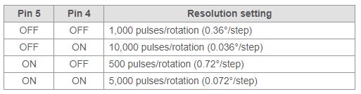
Note:
If the resolution is 1,000 pulses/rotation, the motor makes 3,000 r/min for a 50-kpps command pulse.
If the resolution is 10,000 pulses/rotation, the motor makes 3,000 r/min for a 500-kpps command pulse.
If the resolution is 500 pulses/rotation, the motor makes 3,000 r/min for a 25-kpps command pulse.
If the resolution is 5,000 pulses/rotation, the motor makes 3,000 r/min for a 250-kpps command pulse.
 Automation Systems
  Motion & Power Solutions
  Safety, Vision and IDENT
  Sensing Solutions
  Control Components
  Switching & Accessories
  Switchgear and Trolley Systems
  Process Weighing
  LED Lighting
  Omron
Omron
 Mitsubishi
 Delta
Delta
 Autonics
 Inno
Inno
 Honeywell
 Novotechnik
 Orientalmotor
 Microscan
 IPA
IPA
 Technomech
 Intech
 IOT & Traceability
 Project & Panel Engg.
 Application Case Studies
 Solutions by Industry
 Solutions by Process
 Solutions by Product
 Corporate Information
 Company Profile
 Quality Policy
 Mission Statement
 Chairman's Message
 Intech Group Companies
