Frequently asked questions and answers for Ultrasonic Sensors - Industrial Automation
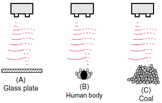
How does the reflection efficiency vary according to the type and the configuration of objects detected by the Ultrasonic Sensors?
Types and configurations of sensing objects(Reflective Type)
Types and configurations of sensing objects are divided broadly into the following categories.
(A) Flat objects: liquid, box, plastic sheet, paper, glass, etc.
(B) Columnar objects: can, bottle, human body, etc.
(C) Granular or aggregated objects: ores, rock, coal, coke, plastic pellet, etc.
Reflection efficiency varies according to the configuration of these sensing objects.
In the case of(A), the largest amount of reflected waves is returned. However, it is greatly affected by the gradient of a sensing object.
In the case of(B) and(C), there is diffuse reflection and reflected waves are non-uniform. However, it is less affected by the gradient of a sensing object.
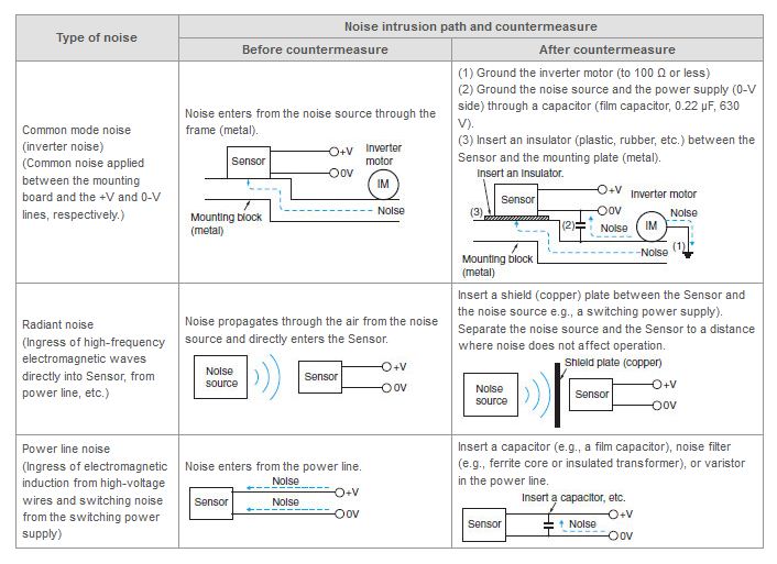
The Ultrasonic Sensor seems to be malfunctioning due to noise. What can be done to resolve it?
Different countermeasures should be used depending on factors such as the path of noise entry, the frequency component, and the peak value. Typical examples are given below.
What happens when multiple Sensors are used and they interfere with each other? What can be done to resolve the problem?
Mutual interference:
An error occurs in the analog value to the Analog Input Unit of the Digital Panel Indicators or Programmable Controllers.
(For example when the input is 10 mA, an input of 4 mA is indicated.)
When this happens, the error indicator (red LED) will begin to flash.
Countermeasure:
Place the Sensors apart from one another so that they do not interfere with each other.
What is the highest ambient temperature that the Ultrasonic Sensor can be used in?
55 °C, but the power supply of E4R Ultrasonic Sensor Amplifier should not be used in an ambient temperature higher than 40 °C.
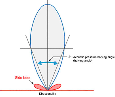
What is a side lobe of Ultrasonic Sensors?
Directionality can be depicted by a graph that shows the sound level in different directions with the center of the oscillator (maximum sound strength) as the reference. In general, the further away the angle from the reference, the smaller the sound level, but after a certain point it begins to increase again. This area is called the side lobe. If this side lobe reflects off a surrounding object, it may affect the detection characteristics of the Ultrasonic Sensor.
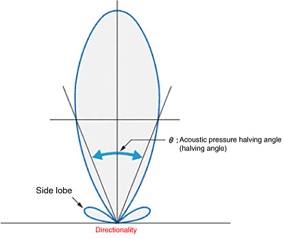
What is meant by the directionality of Ultrasonic Sensors?
The ratio between the sound output of the non-directional wave transmitter (which is required to produce the necessary sound energy to provide to the target object) and the directional wave transmitter is called the directional gain.
The directionality improves as the frequency and the vibration area increase. This means that the sound waves can be generated with better efficiency.
The directionality of a Sensor that is used as an Ultrasonic Switch has an acoustic pressure halving angle of approximately 8° to 30°. The directionality varies largely depending on the shape of the sensor phone and the vibration mode of the oscillator. Therefore the shape of the Sensor, the usable frequency, and the types of oscillators are determined depending on the required operating range.
How is the wiring performed for synchronous operation?
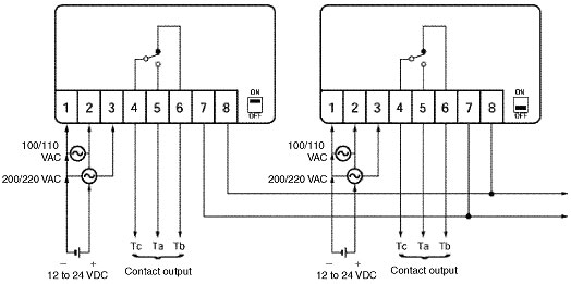
Note:
1.When synchronous operation is required, the slide switch on only one Sensor needs to be ON. The others must be OFF and terminals 7 and 8 must be connected.
2.Synchronous operation can be performed with up to 50 Sensors.
3.Do not place the synchronous wiring (wiring of terminals 7 and 8) together with a power supply line.
4.The cable to be used must be less than 10 mm in diameter. Use a shielded cable for synchronous operation.
5.When performing synchronous operation, turn ON the power for all the E4A-3K Sensors. If any of them are not turned ON, the entire operation will not work.
Single/Synchronous Switch (MON/SYN)
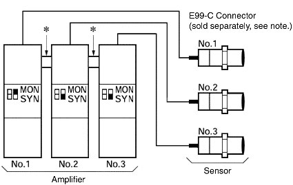
Note:The above connector is very effective for Reflective Sensors. The Through-beam Sensors also requires connection, but the mutual interference is negligible. Refer to the parallel movement characteristics diagram when spacing the Sensors.
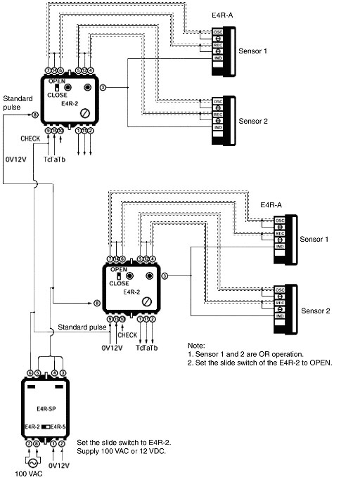
Standard Pulse Unit
When using multiple E4R-2 Power Supplies at one location, use the E4R-SP Pulse Unit.
The pulses generated by the E4R-SP synchronizes the Sensors, so up to ten E4R-2 Sensors can be used for synchronous operation without malfunction due to interference.
If coating compositions and/or water drops adhere to the surface of Ultrasonic Sensors, is the operation affected?
Yes, it is.
Since the sensing distance becomes shorter than the rated sensing distance, the operation in this kind of environment cannot be recommended.
How long can the cable for an Ultrasonic Displacement Sensor or Ultrasonic Sensor be extended?
Power/output cable (labeled as 2 and 3 below) must not be any longer than 10 m.
Use a cable with conductor cross-section of at least 0.3 mm2.
A 10-m cable with connectors is also available.
The cable between the Sensor and Amplifier Unit (labeled as 1 below) must not be any longer than 10 m (combined with the power/output cable (labeled as 2 and 3 below)).
Use a power/output cable with conductor cross-section of at least 0.3 mm2.
A 5-m extension cable to connect the Sensor and Amplifier Unit is also available.
The power/output cable (labeled as 2 and 3 below) must not be any longer than 100 m.
Use a cable with conductor cross section of at least 0.3 mm2.
The cable between the Sensor and the Amplifier Unit (labeled as 1 below) must not be any longer than 20 m, and the power/output cable (labeled as 2 and 3 below) must be 100 m max.
Use a power/output cable (labeled as 2 and 3 below) with conductor cross-section of at least 0.3 mm2.
(Use a 6-mm-diameter (UL 20276 (7/0.25 dia.) shielded 2-conductor cable for the E4C-TS50S.) For the E4R, use an 11/0.16-dia. parallel 1-conductor shielded cable.

Which Sensors can be used for synchronous operation without causing mutual interference?
The following Sensors can be used.
E4A-3K Ultrasonic Sensor
E4C Series Ultrasonic Sensor
E4R Series Ultrasonic Sensor
When a cover is placed on the Ultrasonic Sensor sensing surface, does it affect the sensing?
If the cover is within the propagation area of the ultrasonic waves, the cover will be detected, and thus it affects sensing.
Which Ultrasonic Sensors have a long detection distance?
The E4PA Ultrasonic Displacement Sensor has a long detection distance. Details are provided below.
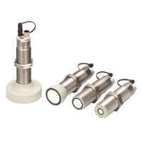


Note:When you use a 4-pole sensor connector cable, the E4PA-C01 is useful for converting from 4 to 5 poles. If this is done, however, you cannot use the mutual interference prevention function.
When using the Ultrasonic Sensors, what precautions are necessary for surrounding environment?
Do not use the Ultrasonic Sensors at a temperature exceeding the rated range or outdoors, otherwise the reliability and life of the Ultrasonic Sensors will decrease.
The Ultrasonic Sensors utilize the air as a beam transmission media. Do not use them in places with radical convection or extreme local temperature changes. For example, if there is a hot air curtain that causes turbulence within the sensing area, the Ultrasonic Sensors may malfunction.
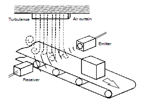
The jetting sound of air nozzles includes noise of a wide frequency range, which will affect the operation of the Ultrasonic Sensors. Do not use an air nozzle near them.
The sensing distance of the Ultrasonic Sensors will decrease if there is any water drops on the surface of the emitter or receiver.
The reflective model may not detect any objects if there is any object absorbing sound, such as powder and cotton, on the surface of the emitter or receiver.
The Ultrasonic Sensors cannot be used in a vacuum or explosion-proof area.
Do not use the Ultrasonic Sensors in a vaporous place because non-uniform steams cause difference in temperature and therefore measurement error is observed.
What are the reflective and through-beam sensing methods?
Between similar mediums, ultrasonic waves move straight forward, but when the mediums differ, the waves will either reflect or pass through at the border. What the waves do depends on the type and shape of the medium.
In normal atmosphere, reflection from any object (even human bodies) is well transmitted so detection of that object is easy.
What is linearity of Ultrasonic Sensors?
Linearity is the error in the linear output compared to the ideal value that describes the relationship between the distance and the linear output when the temperature and voltage are at fixed values.
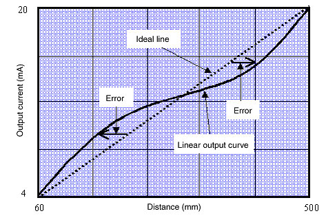
(Example)
The linearity of E4PA-LS50-M1 Ultrasonic Sensor is ±1% FS (FS: 500 mm − 60 mm = 440 mm).
Converting this to a dimension,
Dimension error = ±1% × 440 mm= ±4.4 mm
Therefore, compared with the ideal direct line, there is an error of ±4.4 mm max.
What is a sensing area of Ultrasonic Sensors?
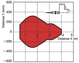
When a standard sensing object enters the red zone, it can be detected.
When there is a background object in the red zone, the background will be detected.
What is resonance of Ultrasonic Sensors?
When an electrical signal is applied in pulses at a frequency close to the resonance frequency of the oscillator, even after the electrical signal has stopped, the ultrasonic vibration remains.
This is called resonance.
For a Reflective Sensor, if this continues for a long time, detection becomes impossible.

What is synchronous operation?
Synchronous operation can be used when using multiple Ultrasonic Sensors to prevent mutual interference between the Sensors by emitting the ultrasonic waves from each Sensor at the same time (by synchronizing them).
Prevention of mutual interference using synchronized operation is possible only when the Sensors are placed at different detection distances, and their sensing ranges do not overlap.
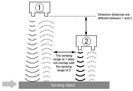
What is mutual interference?
Mutual interference is when the ultrasonic waves of adjacent Ultrasonic Sensors affect the outputs and makes them unstable.