Automation Systems
  Motion & Power Solutions
  Safety, Vision and IDENT
  Sensing Solutions
  Control Components
  Switching & Accessories
  Switchgear and Trolley Systems
  Process Weighing
  LED Lighting
  Omron
Omron
 Mitsubishi
 Delta
Delta
 Autonics
 Inno
Inno
 Panasonic
 Novotechnik
 Orientalmotor
 Microscan
 IPA
IPA
 Technomech
 Intech
 Honeywell
 IOT & Traceability
 Project & Panel Engg.
 Application Case Studies
 Solutions by Industry
 Solutions by Process
 Solutions by Product
 Youtube Videos
 Corporate Information
 Company Profile
 Quality Policy
 Mission Statement
 Chairman's Message
 Intech Group Companies

Compact Industrial SCARA
Compact Industrial Robot with light weight space saving arm. Its high speed operation is best suited for pick and place, labelling, tracking

last update: December 03, 2014
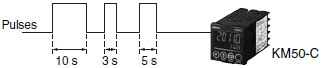
1. Flow rates can be measured at the same time as power by inputting flow pulses. (Two inputs are supported.) To support energy-saving analysis, power consumption can be compared with the flow rate of air, gas, or other fluids with a single Unit.
2. Pulse inputs can be counted, or used to measure the ON time. The consumption rate of a device can be measured by dividing the power consumption with the measured number of operations or operation time.

KM50 Power Monitors have a thermistor chip built onto the panel surface for easy measurement of the panel surface temperature.
The temperature display can be offset to match the room temperature to manage trends.
In addition to the consumed energy (total regenerative power consumption), generated power (total regenerative energy) can also be measured.
A single Power Monitor can measure equipment that effectively uses power generated by reverse motor rotation.
In addition to instantaneous reactive power, the total leading or lagging power consumption can also be measured.
Together with peak power measurements, this function aids with monitoring the power distribution equipment.
Automatic range switching enables high-accuracy measurements even for microcurrents.
Standby and stopped power can be accurately measured.
When measured at the distribution board, the total of the distributed values is almost the same as the base measurement.
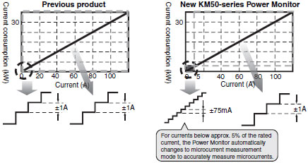
You can measure microcurrents of ±75 mA with a CT with a rated current of 100 A. (Reference Value)
You can measure microcurrents of ±4 mA with a CT with a rated current of 5 A. (Reference Value)
Note: Reference values are typical values. Actual values may vary.
Measurements can be made on the primary side of an inverter.
Power consumption can be measured even after installing inverters which are widely used to save energy. This enables you to accurately grasp the effect obtained by introducing the inverter.
The total power consumption can be converted to the equivalent monetary cost.
Displaying the cost of the wasted energy can be used to support energy-saving measures.
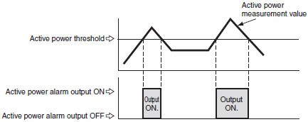
Alarms can also be set up for generated power (regenerative power), current, voltage, power factor, or reactive power to assist plant monitoring.
Data can be saved as follows: 5-minute data for two days, 1-hour data for eight days, 1-day data for month, and 1-month data for one year.
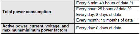
*1. The data that is logged with a 5-minute cycle can be read out only by using RS-485 communications. Readout is not possible with key operations on the Power Monitor. *2. Up to 48 hours of data can be read out using communications.
Incorrect voltage wiring can be detected.
If any mistakes were made during installation, they are automatically detected, reducing the time required for checking after installation.
This also reduces the risk of having to restart when a mistake is found.
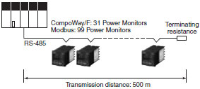
Up to 99 KM50 Power Monitors can be connected using RS-485 Modbus.
The energy use of each device can be managed with minimal wiring.
last update: December 03, 2014
last update: December 03, 2014
Rated primary current of 5 A: KM20-CTF-5A
Rated primary current of 50 A: KM20-CTF-50A
Rated primary current of 100 A: KM20-CTF-100A
Rated primary current of 200 A: KM20-CTF-200A
Rated primary current of 400 A: KM20-CTF-400A
Rated primary current of 600 A: KM20-CTF-600A
KM20-CTF-CB3 (3 m)
last update: December 03, 2014