A Basic Switch is a small switch with a very small contact gap and snap-action mechanism and with a contact structure that switches for a specified movement and specified force enclosed in a case with an actuator provided on the exterior of the case.
A Basic Switch is a small switch with a very small contact gap and snap-action mechanism and with a contact structure that switches for a specified movement and specified force enclosed in a case with an actuator provided on the exterior of the case.
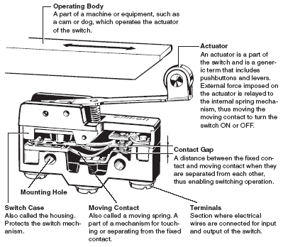
The following Basic Switch structure is shown as an example. Basic Switches are mainly comprised of five components.
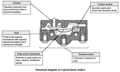
Basic Switch:A small-size switch with a very small contact gap and snap-action mechanism and with a contact structure that switches by a specified movement and specified force enclosed in a case with an actuator provided on the exterior of the case. (Basic switches are often referred to as merely "switches" in this catalog.)
Switch with Contacts: A type of switch that achieves the switching function through the mechanical switching of contacts. Use as opposed to a semiconductor switch with switch characteristics.
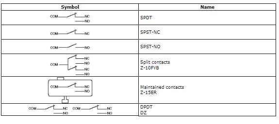
Contact Form:The structure of the electrical I/O circuits of contacts used according to the type of application. (Refer to Contact Form table later in this section.)
Ratings:Value generally used as a reference for ensuring the characteristics and performance of switches, such as the rated current and rated voltage. Ratings are given assuming specific conditions (such as the type of load, current, voltage, and frequency).
Resin Filled (Molded Terminal):A terminal which is filled with resin after being connected to the internal circuit of the switch with a lead to eliminate exposed current-carrying metal parts and thereby to enhance the drip-proof properties of the switch.
Insulation Resistance: The resistance between discontinuous terminals, between terminals and non-current-carrying metal parts, and between terminals and ground.
Dielectric Strength: The threshold value up to which insulation will not be destroyed when a high voltage is applied for 1 minute to a predetermined measurement location.
Contact Resistance:The electrical resistance of the contact point of contacts. Generally, the contact resistance includes the conductive resistance of the spring or terminal section.
Vibration Resistance:Malfunction: The range of vibration for which closed contacts will not open for longer than a specific time when vibration is applied to a switch currently in operation.
Shock Resistance:Destruction: The range of shock for which the components of the switch will not be damaged and for which operating characteristics are maintained when mechanical shock is applied to a switch during transportation or installation. Malfunction: The range of shock for which closed contacts will not open for longer than a specific time when shock is applied to a switch currently in operation.
Switch Configuration and Structure
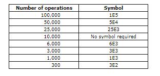
Mechanical Durability: The switching durability when a switch is operated at a specified frequency and specified overtravel (OT) without the contacts energized.
Electrical Durability: The switching durability when a switch is operated at a specified frequency and specified overtravel (OT) under the rated load.
Switches are tested under the following conditions.
Ambient temperature: 20 ± 2°C
Relative humidity: 65 ± 5%RH
Atmospheric pressure: 101.3 kPa
The N-level reference value indicates the failure rate of the switch.
The following formula indicates that the failure rate is 1/2,000,000 at a reliability level of 60% (?60).
?60 = 0.5 × 10⁻⁶/operations
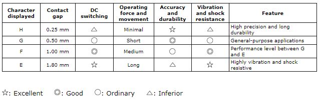
The contact gap is either 0.25, 0.5, 1.0, or 1.8 mm. The contact gap is a design goal. Check the contact gap of the switch to be used if a minimum contact gap is required. The standard contact gap is 0.5 mm. Even for the same switch configuration, the smaller the contact gap of a switch mechanism is, the less the movement differential (MD) is and the more sensitivity and longer durability the switch has. Such a switch cannot ensure, however, excellent switching performance, vibration resistance, or shock resistance.
A switch becomes less sensitive when the movement differential (MD) increases along with the contact gap due to the wear and tear of the contacts as a result of current switching operations. If a switch with a contact gap of 0.25 mm is used for its high sensitivity, it will be necessary to minimize the switching current in order to prevent the wear and tear of the contacts as a result of current switching operations.
A switch with a wide contact gap excels in vibration resistance, shock resistance, and switching performance.
For information on the MD (movement differential), refer to the terms related to operating characteristics.

A snap-action mechanism is the mechanism by which the moving contact quickly moves from one fixed contact to another fixed contact with minimal relation to the speed at which the switch is operated. If the handle of a knife switch, for example, is moved quickly, the action is referred to as quick, but the mechanism by which the speed at which the handle is moved directly correlates to the movement speed of the contacts is referred to as slow-action movement rather than snap-action movement. The faster the contact switching speed, the shorter the connection time for arcing generated between the contacts.
As a result, contact wear and damage are reduced, and stable characteristics can be maintained. At this switching speed, however, in addition to mechanical limits, there is a limit to the speed that is effective to reduce arcing (i.e., economical speed). In particular, if the switching speed is too high when the circuit is open, the increased collision energy of the moving and fixed contacts will cause bouncing, and the arcing that is generated will produce marked wear on the contacts and contact welding may render the circuit unable to open.
To perform this quick action, a spring mechanism is used. The spring mechanism generally uses a dead point, which is the critical action point when one condition changes in a springing manner to another condition.
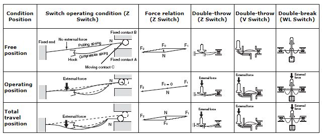
The following figure shows an example of a snap-action mechanism that combines the pulling spring and the compression spring of a Basic Switch.
The following section provides a description of the operating principles of the snap-action mechanism for double-throw Z-series Switches.
As shown in the following figure on the Switch force relationship, compression spring counterforce F1 is at equilibrium because of forces F2 and F0 at the free position where no external force is applied to the actuator. F0 is the force at which moving contact C is pushed to the other contact, fixed contact B.
Next, force is applied to a part of the pulling spring through the actuator, the pulling spring is displaced, forces F1 and F2 at point N progressively increase until the two angles together approach 180°, and eventually equilibrium is reached with only F1 and F2, i.e., F0 = 0. Between the free point and the point where F0 = 0, a bending action works to move the contact horizontally, and the compression spring is even further bent.
From the position where F0 = 0, a minute displacement applied to the pulling spring because of external force produces a force in the opposite direction, F0, the strong force of the maximally bent compression spring sharply pushes moving spring C downward, and moving spring C transfers to the opposing fixed contact A by crossing open space.
Basic Switches use these operating principles to perform contact switching at a switching speed (i.e., opening speed) specific to the switch, regardless of the speed of the force with which the pulling spring is pushed. The position at which F0 = 0 is referred to as the operating position, which nearly corresponds with the position at which a part of the pulling spring passes through the dead point. The same operating principles apply if a releasing operation is performed when the external force is removed. The driving force, however, will be the opposing force of the bent spring.
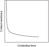
The contact resistance depends on the contacting force. The following figure shows the relationship. The contacting resistance becomes stable (i.e., smaller) as the contacting strength increases. Conversely, the contacting resistance becomes unstable (i.e., larger) as the contacting strength decreases.
Contact Resistance vs. Contacting Force
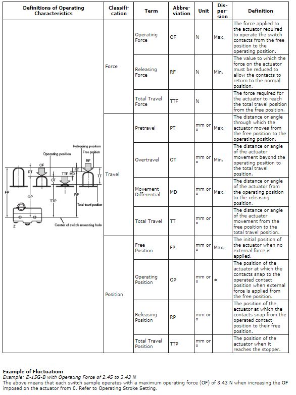
The operating characteristics of Basic Switches are expressed in terms of force vs. stroke. The figure at the below shows this relationship. The stroke (i.e., actuator movement) is given on the horizontal axis and the force applied to the actuator is given on the vertical axis. The following describes the characteristics of Basic Switches.
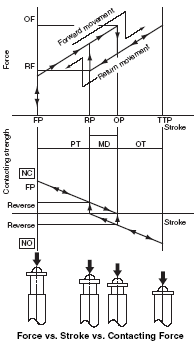
The relation between the stroke and the operating force is shown in the figure above. The contacting force at the free position decreases as the actuator is pressed in, and reaches zero when it is pressed to the OP. The moving contact inverts from the normally closed (NC) side to the normally open (NO) side, and a contacting force is immediately produced. The NO-side contacting force increases when the actuator is further pressed in. When the actuator returns, a contacting force is produced on the NC side after the NO side becomes zero.
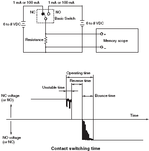
The figure below shows the relation between operating speed and contact switching time. Contact switching time increases as the actuator operating speed decreases. The contact switching time is therefore measured at the minimum operating speed. For the measurement circuit in the figure below, the applied current is 1 mA for microload Basic Switches and 100 mA for standard Basic Switches.
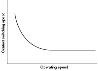
As shown in the figure above, the contact switching time is the sum of the unstable time, reverse time, and bounce time, which is 5 to 15 ms for general Basic Switches. The unstable time here derives from the contact resistance instability due to contact wiping and the decrease in contacting force immediately before the contact reversal described above.
The reverse time derives from the mechanical reversing of the snap-action mechanism. Bounce time derives from the bouncing that occurs when the moving contact collides with the fixed contact. During the unstable time and bounce time, the contacts become heated, which causes contact welding and may result in incorrect operation of the electronic circuit for connections made with the electronic circuit. The Basic Switches are therefore designed to minimize unstable time and bounce time.
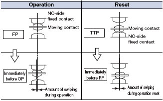
Wiping may occur on the contacts or barely occur at all depending on the type of snap-action mechanism. Wiping is the action of the moving contact wiping the surface of the fixed contact based on the contacting force. The following figure illustrates wiping during operation and reset of the moving contact.
Wiping has the effect of removing contact welding caused by inrush current and cleaning the contact surfaces.
