In the manufacturing industry, production consists of processing, assembling, and transporting materials. In modern times, machines use large amounts of energy to absorb the burden from workers to assist in production. This result in the wide range of development in machines that we see today. And trained workers based on experience in operating the machines create more stable quality, causing the relationship between machines and production to continue and evolve into many forms today.
In the manufacturing industry, production consists of processing, assembling, and transporting materials. In modern times, machines use large amounts of energy to absorb the burden from workers to assist in production. This result in the wide range of development in machines that we see today. And trained workers based on experience in operating the machines create more stable quality, causing the relationship between machines and production to continue and evolve into many forms today.
In some countries, changes in social structure have brought changes in the people that work at production sites. For example, many experienced workers are retiring while the working population shrinks due to lower birth rates. At the same time, forms of employment continue to diversify, such as the increasing number of temporary employees and there is a continued increase in employees working overseas. Diversification also continues to increase in other ways, such as age, sex, experience, language, and social habits.

Today's society is facing more diversification in consumer needs driving demands for more variation in products. Production sites are required to change between many different products at relatively short intervals, resulting in frequent changes to production facilities. Machines required for production must support more functionality. This and many other changes require that workers must master new techniques and working procedures.

Market globalization has taken production sites from fixed sites across national borders. Domestic production is faced with the need for more competitive products and new markets combined with demand for production sites in newly industrialized countries, such as BRICs. Offshore production means dealing with different laws, infrastructures, cultures, and values. The machines and production facilities resulting from the accumulated know-how of industry domestically must now be used in different human environments.
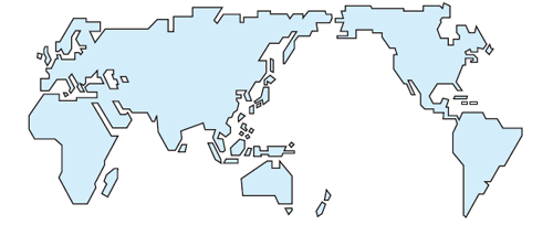
In mature civil societies, companies must take social responsibility for their activities. For example, they must assume product liability for the products that they produce. Although conditions vary by country, all countries now have laws requiring product safety to protect the consumer. (For example, Japan and the USA have product liability laws and the EU has the EC directives.) It is not necessary to provide examples of product accidents to realize the very strict monitoring of manufacturing liability for safety and ease of mind in societies that share a common ideal of respect for human beings. And based on these ideals, the responsibility of companies for the safety of workers on production sites is also strictly monitored. (For example, OSHA in the USA, the Revised Industrial Safety and Health Law in Japan, and EC directives in the EU.) Companies face not only criminal, civil, and damage liability for any accidents that might occur, but their corporate image is greatly hurt as a result. The social liability of companies for the safety of their workers has skyrocketed in recent years.
The relationship between workers and machines and the environment in which they operate has thus changed on a global scale. And yet, manufacturing is not possible until a worker operates a machine. Across changes in the operating environment, society demands that machines and production facilities can be used safely regardless of where they are used or who uses them. This is required not only in the workers, but also in the machines and hardware technology. As a result, global standards for safety are required for today's production sites. This is the concept of Machine Safety.
The European Standards (EN Standards) in force since 1993 are representative standards on machinery safety. They are technical standards enacted to ensure compliance with basic safety requirements stipulated by the Machinery Directive across Europe, and compliance with these standards is a condition for obtaining the CE marking, required since 1995 for distribution in Europe. The following sections describe the basic concepts of machinery safety. These safety concepts are currently incorporated into the safety standards of each country as standard international safety concepts.
Hazards occur in areas where machine work areas (machine operating output) and human work areas overlap.
Classifications and Examples:
The general hazard classifications according to EN ISO 12100-1, where the basic concepts of machinery safety are defined, are shown below.
Crushing, entanglement, stabbing or puncturing, shearing, drawing-in or trapping, friction or abrasion, cutting or severing, high-pressure fluid ejection, etc.

Contact by a person with live parts, i.e., parts that normally carry a voltage, or parts that have become live under faulty conditions, especially as a result of an insulation failure, etc.
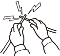
Burns and scalds from flames, explosions, radiation from heat sources, etc.

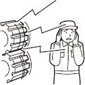
Hearing loss, tinnitus, etc.
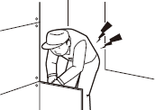
Serious damage to the entire body, particularly to the hands, arms, and lower back.

Low frequencies, radio frequencies, ultraviolet, infrared, X-rays, etc.

Toxins, irritants, dust, explosions, etc.

Unhealthy postures, human error, etc.
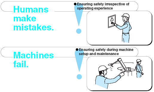
All machines fail and everyone makes mistakes. Therefore, basic designs that take every precaution to ensure the safety of workers is required in the event of a fault.
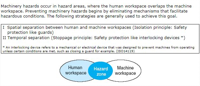
Machinery hazards occur in hazard areas, where the human workspace overlaps the machine workspace. Preventing machinery hazards begins by eliminating mechanisms that facilitate hazardous conditions. The following strategies are generally used to achieve this goal.
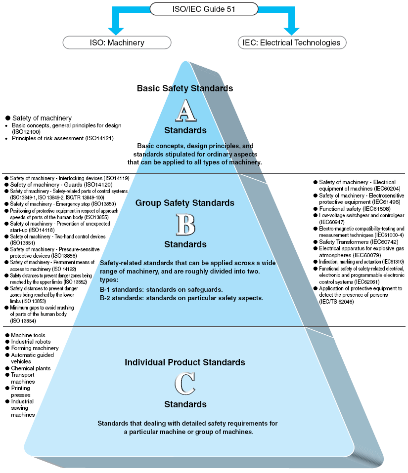
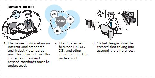
The International Electrotechnical Commission (IEC) prepares international standards for all electrical, electric and related technologies, and the International Organization for Standardization (ISO) prepare international standards for all technologies other than electrical and electric technologies (machinery and management). European countries often take the initiative in proposing the standards and establishing them as ISO/IEC international standards.
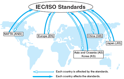
1. Europe's EN Standards are produced by CEN/CENELEC.
2. IEC/ISO international standards are implemented without duplicating the efforts of various agreements.
3. Member countries of the WTO/TBT Agreements shall ensure the adoption of international standards as own national standards.
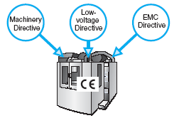
There are approximately 300 EC Directives issued for harmony in Europe. The EC Directives are equivalent to law in 18 countries in Europe. The EC Directive for machinery is called the Machinery Directive. The Machinery Directive (EC Directive 98/37/EC) restricts the export to Europe of machinery without the CE Marking as of January 1, 1995. The Machinery Directive requires that machinery satisfy the three pillars of safety: mechanical safety, electrical safety, and worker safety. Specifically, among other regulations, EN 292 must be satisfied for machinery, EN 60204-1 and IEC 60204-1 for electrical systems, and VBG for accident prevention.
The new directive (2006/42/EC) was issued June 9, 2006. It will be implemented from December 29, 2009.
According to the EC Directive (EC Directive 2006/95/EC), low voltage devices are devices that operate at 50 to 1,000 VAC or 75 to 1,500 VDC. The LVD applies to almost all electrical devices from electrical household appliances and office equipment to industrial electrical machinery. The LVD pertains to electrical safety in the Machinery Directive, along with the EMC Directive.
The EC Directive for EMC devices is called the EMC Directive (EC Directive 89/336/EEC and New EMC Directive 2004/108/EC are scheduled to be effective.). EMC stands for “electromagnetic compatibility.” When measures have been taken for both electromagnetic interference (EMI) and electromagnetic susceptibility/immunity (EMS), the device is called electromagnetically compatible, which means that EMC measures have been successfully applied.
The CE Marking is a mark of compliance with the EC Directives. The CE Marking indicates that the product complies with the stipulated level of protection in all relevant EC Directives. Devices labeled with the CE Marking may be imported and exported to Europe without restriction. You might call the CE Marking a “passport” to Europe.

As explained above, all relevant EC Directives must be satisfied for a product to be labeled with the CE Marking. EN Standards complement the EC Directives. Satisfying the EN Standards alone, however, does not result in the EC Directives being satisfied. Countermeasures for product liability is mainly required in manuals and catalogs.
These basic requirements are listed in Machinery Directive Appendix I. The Preliminary Observations of the Annex I of Machinery Directive are introduced below.
1. The obligations laid down by the essential health and safety requirements apply only when the corresponding hazard exists for the machinery in question when it is used under the conditions foreseen by the manufacturer. In any event, requirements 1.1.2, 1.7.3 and 1.7.4 apply to all machinery covered by this directive.
2. The essential health and safety requirements laid down in this Directive are mandatory. However, taking into account the state of the art, it may not be possible to meet the objectives set by them. In this case, the machinery must as far as possible be designed and constructed with the purpose of approaching those objectives.
3. The essential health and safety requirements have been grouped according to the hazards which they cover.
Machinery presents a series of hazards which maybe indicated under more than one heading in this Annex. The manufacturer is under an obligation to assess the hazards in order to identify all of those which apply to his machine; he must then design and construct it taking account of this assessment.
Standards for countries in the European region are unified by CEN and CENELEC. The unified standards are called European Norm (EN) and "EN" is added to the front of the standard numbers. When new EN Standards are established, each country in the region must replace its relevant domestic standard with the EN Standard normally within six months. Applicable standards for products intended are not indicated in the EC Directives. The EN Standards that must apply are published separately in the Official Journal of the European Communities (OJEC). Manufacturers are therefore necessary to determine the design specifications based on the EN Standards published in the OJEC. In addition to official EN Standards, Drafts of European Standards (prEN), Harmonization Documents (HD), European Pre-standards (ENV), and CEN Reports (CR) are also published.
The General Product Safety Directive and Product Liability Directive are complementary regulations but their scope is not identical. The Product Liability Directive applies to virtually all products, while the General Product Safety Directive applies only to new, used, and reconditioned products intended for or used by consumers. Both regulations, however, include areas of uncertainty. Therefore, to be especially careful, a manufacturer must compare the individual provisions of all directives that apply to its product.

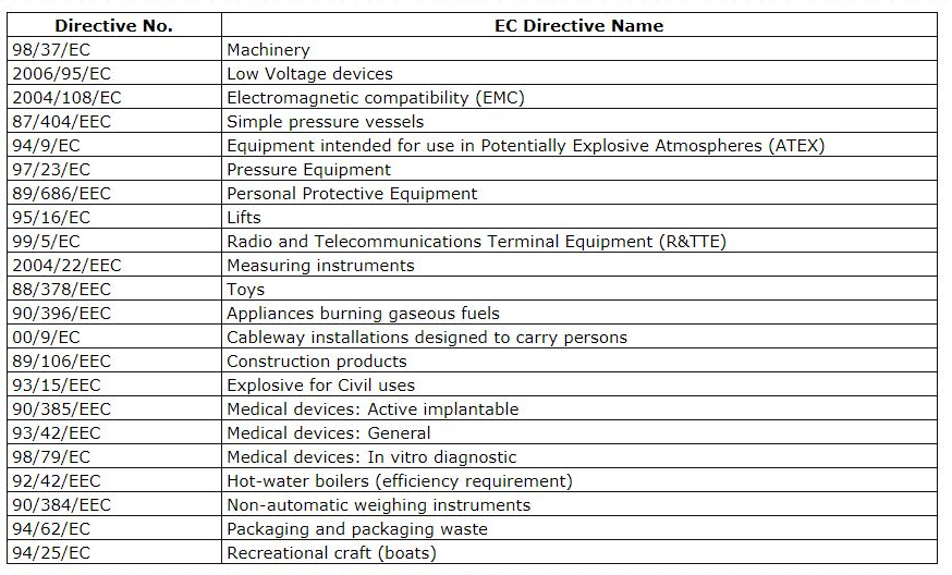
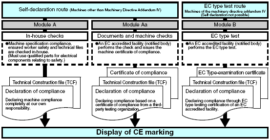
(Machines to which the machinery directive applies are machines and safety components)
(A) Machines
(1) Circular saw machines for cutting wood materials and meat (Single blades/multi-blade)
(2) Hand-fed surface planing machines for woodworking
(3) Thicknessers for one-side dressing with manual loading and/or unloading for woodworking
(4) Band saw machines for cutting wood materials and meat
(5) Combined machines of the types referred to in (1) to (4) and (7)
(6) Tenoning machines
(7) Hand-fed vertical spindle molding machines for working with wood and analogous materials.
(8) Portable chainsaws
(9) Presses (Have a travel exceeding 6 mm and a speed exceeding 30 mm/s)
(10) Injection or compression plastics-molding machines
(11) Injection or compression rubber-molding machines
(12) Machines for underground working
(13) Manually-loaded trucks for the collection of household refuse incorporating a compression mechanism
(14) Transmissions
(15) Vehicles servicing lifts
(16) Devices for the lifting of persons involving a risk of falling from a vertical height of more than three meters
(17) Machines for the manufacture of pyrotechnics
(B) Safety components
(1) Electro-sensitive devices designed specifically to detect persons in order to ensure their (non-material barriers, sensor mats, electromagnetic detectors, etc.)
(2) Logic units which ensure the safety functions of bimanual controls
(3) Automatic movable screens to protect the presses referred to in (9), (10) and (11) of (A)
(4) Roll-over protection structures (ROPS)
(5) Falling-object protective structures (FOPS)
Note: New machinery directives are scheduled to be enacted in 2009. Therefore, there is the possibility that this flowchart will also be changed to reflect the new directives.
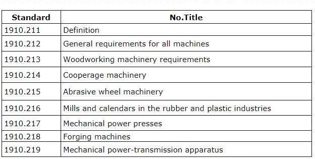
The Occupational Safety and Health Act (OSHA) passed in 1970 to provide safe and healthy working conditions. Part 1910 of the 29th Code of Federal Regulations (CFR) gives specific standards. Subpart O of Part 1910 sets standards for machinery and machine guarding, and divides into Part1910.211 to Part 1910.219.
Paragraph (a)(1)
One or more methods of machine guarding shall be provided to protect the operator and other employees in the machine area from hazards such as those created by point of operation, ingoing nip points, rotating parts, flying chips, and sparks. Examples of guarding methods are barrier guards, two-hand tripping devices, electronic safety devices, etc.
Paragraph (a)(3)(ii)
The point of operation of machines whose operation exposes an employee to injury shall be guarded. The guarding device shall be in conformity with any appropriate standards, therefore, or, in the absence of applicable specific standards, shall be so designed and constructed as to prevent the operator from having any part of his body in the danger zone during the operating cycle.
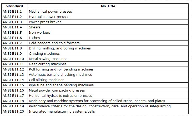
ANSI is an independent standards organization in the USA. It does not create any standards by itself, but rather approves and registers US standards created in various fields. For example, in 1976 ANSI approved the Underwriters Laboratories (UL), which was established by the fire insurance industry. Manufacturers of industrial robots in Japan and many other countries worldwide use the requirements for safety of industrial robots and robotic systems given in ANSI/RIA R15.06, which forms the basis of ISO 10218. ANSI/B11.19 safety standards for machine tools were established in 2003 and have become important standards.
The American Society of Mechanical Engineers (ASME) collaborates in creating ANSI Standards, which are often adopted as ANSI B Standards. The main safety standards for machine tools are stipulated by ANSI B11.
Purposes for Using Safety Equipment
To ensure the safety of operators, safety and protective equipment is designed to prevent any hazardous machine motion or stop the machine when the operator's hand or other body part enters the hazard zone. The following items are demanded of safety and protective equipment.
OMRON safety components can be used when constructing safety-related systems conforming with the requirements of ANSI B11.19 and ANSI/RIA R15.06.
The amended Industrial Safety and Health Act went into effect in 2006, with the purpose of providing an environment for the promotion of independent safety and health activities in offices. For example, the Act includes requirements to investigate dangers and hazards in the workplace and take necessary measures against them. The Act incorporates a framework to identify dangers and hazards, evaluate risks, and implement measures to reduce these risks.
In July 2007, the Ministry of Health, Labor and Welfare in Japan amended its Guidelines for Comprehensive Standards of Machinery, which was originally issued in June 2001 in response to the basic safety standards provided in ISO 12100. These Guidelines stipulate the procedure for manufacturers to use in reducing safety risks and achieve designs that take safety into consideration in the manufacture of production equipment and machinery, and also request that users provide safety measures when they introduce and use the equipment and machinery.
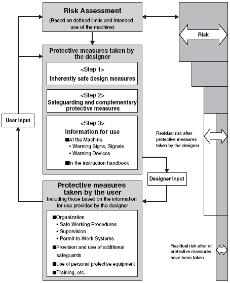
In other words, the measures that ensure safety in machinery include measures that manufacturers build-in at the design stage and measures that users must take when using the machinery. However, the Guidelines also clarify the fact that the measures that manufacturers build-in at the design stage must naturally precede the measures taken by the users. The following diagram shows the flow of achieving machinery safety based on the information in the Guidelines for Comprehensive Machinery Safety Standards.
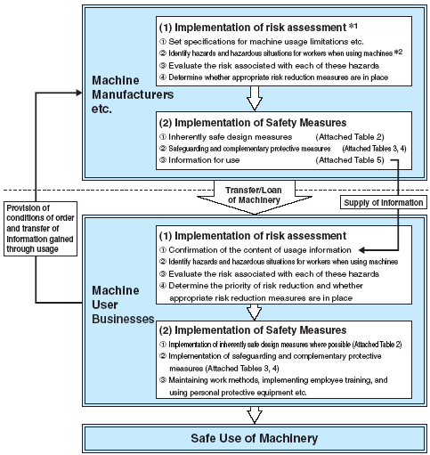
*1. In the Attachment, “risk assessment” is referred to as “assessment of hazards and dangers”.
*2. In the Attachment, “hazards” is referred to as “hazards and dangers”.
The regulations and standards of individual countries must be brought in line with international standards to remove trade barriers and thus ensure free trade worldwide. To that end, Japan accepted the terms of the World Trade Organization (WTO), becoming a member and signatory to the WTO Agreement as well as the TBT Agreement (Technical Barrier Treatment). In 1995, Japan declared its commitment to a system of global cooperation. Growing pressure to adopt international standards triggered a complete overhaul of the JIS standards, which were enacted under the Industrial Standardization Law, to bring them in line with the framework of the international IEC and ISO standards. The new JIS standards will be shifted to the hierarchical system comprised of type A (basic safety standards), type B (generic safety standards) and type C (machine safety standards) standards so that Japanese standards will conform to international standards.
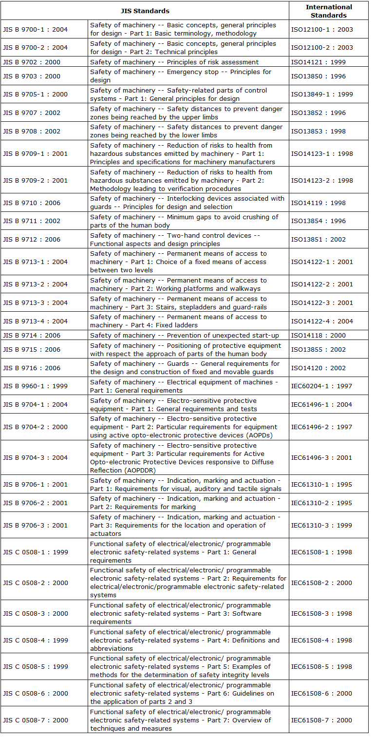
Standards for electrical equipment are produced based on IEC standards.

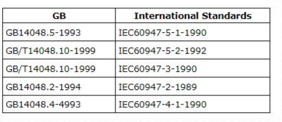


Upon its entry into the World Trade Organization (WTO) in 2001, China integrated its former Certification System for Imported Items and Certification System for Items Distributed within China, and issued the New Compulsory Certification System on December 3, 2001, which took effect on May 1, 2002.
On August 1, 2003 it became prohibited to import or sell products that were not certified under the new certification system. The first list of products to be subject to the New Compulsory Certification System consisted of 132 products in 19 groups.
These products were required to display the China Compulsory Certification (CCC) mark.
South Korea became a WTO member and signatory to the TBT Agreement (Technical Barrier Treatment) in 1995, the year the WTO was created, and declared its commitment to a system of global cooperation. As a result, the Korean Industrial standards (KS) were established by the Industrial Standardization Law as part of an overall obligation to employ international standards, and are in line with the framework of the international IEC and ISO standards.
The S-mark is a voluntary certification system established in November 1997 by the Korea Occupational Safety and Health Agency (KOSHA) to reduce the occurrence of work-related accidents. The S-mark is granted for products that have been examined by KOSHA and are deemed to satisfy standards based on the Industrial Safety Maintenance Law, Article 34, item 2, for product safety, product reliability, and the quality control capabilities of the manufacturer.
In the case of OMRON, “Safety Components” have been certified for both safety and EMC, and basic sensors have received EMC certification. For details of certified models refer to the Safety Components Series Catalog (Y106).
Machine standards are created based on ISO standards, and electrical standards are created based on IEC standards
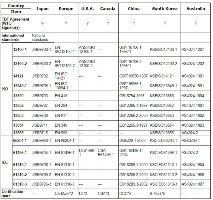
*1. ISO/TR 12100-1: 1992, ISO/TR 12100-2
*2. Self-declaration is allowed for general machines in the Machinery Directive.
*3. UL and CSA are mutual certification systems.
*4. As of April 2006. Certification is not required for the field of industrial machinery.
*5. S-mark certification requires Labor Department approval of safety certification regulations in addition to standards compliance.
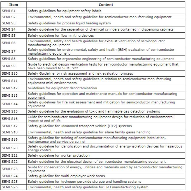
SEMI, which is an abbreviation of Semiconductor Equipment and Materials International, was established in 1970 as an international industry association for semiconductor manufacturing equipment and materials manufacturers. SEMI standards have been established as independent industry standards. There are separate standards for materials (M Series), Facilities (F Series), Flat Panel Displays (D Series), and Traceability (T Series), and the S Series governs environment, health and safety (EHS). These standards have been employed by many equipment users, primarily in the United States. Their headquarters are in California, and there are 11 offices in 8 countries around the world, including in Tokyo.
The responsible machine or process designer no longer considers the production requirements and adds safety systems later, but addresses the two issues as a whole. Legislation demands that the machine or process design meets the necessary safety standards and regulations - it is a legal requirement.
Different types of machines will have different levels of associated risk. These risk levels need to be addressed for the whole machine life span. In particular the requirements at commissioning, application/usage and decommissioning of the machine must be considered.
Risk assessment according to ISO14121 is a series of logical steps that enables designers and safety engineers to examine in a systematic way the hazards arising from the use of machinery so that appropriate safety measures can be selected.
ISO14121 - Safety of Machinery - Principles for Risk Assessment
The main objective is to describe a systematic procedure for risk assessment so that adequate and constant safety measures can be adopted. These are appropriate during the design, construction, modification, use and decommissioning of the machine. The safety of machines can be determined in 5 steps. Documentation of the risk assessment process must be kept.
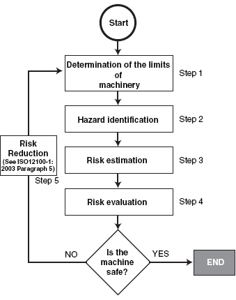
Defining machine limits requires the following points to be considered when assessing risk.
Hazard identification means checking for all the hazardous conditions and hazardous events associated with the machine. This involves predicting hazards that may be caused by the machine, such as the following:
Mechanical hazards: Severing, entanglement, crushing, etc.
Electrical hazards: Contact with live parts, static electricity, etc.
Thermal hazards: Health disorders due to contact with high-temperature parts or working in a high-temperature or low-temperature environment
Methods for clarifying hazards include the following:
After checking for hazardous conditions and hazardous events, the risk factors are determined and the risks are estimated from the degree or possible harm and the probability of the hazard occurring.
After estimating the risk, the risks are evaluated to determine whether the level of risk must be reduced.
If the level of risk must be reduced, safety measures, such as changing the design or providing safeguards, are taken.
The following actions are taken.
ISO 12100 (-1/-2) has been formed into JIS standard JISB9700 (-1/-2). The main purpose of this standard is to set out a framework and directions for general machine safety, so that designers can design safe machines.
The introduction of ISO12100-1:2003 states that “The concept of safety of machinery considers the ability of a machine to perform its intended function(s) during its lifecycle where risk has been adequately reduced”. The 3-step method, which is an expression of this risk reduction methodology, has been further implemented into the “Risk Reduction Process” illustrated on the following page, but it does not yet seem to have been fully recognized in actual applications. ISO12100-2 sets out examples of various measures, a sample of which are shown below.
The size of the machine risk is evaluated according to ISO 14121 and measures are taken to reduce the risk. Measures to reduce risk, however, include design measures and mounting safety devices. First, the measures are taken in the design and the category that should be selected is determined by considering two factors: the degree of potential injury (from slight to serious) according to the Category Assessment Table at the right, and the probability of that injury occurring (from almost never to always).
The safety category for safety-related parts of control systems in sometimes assessed assigning one category for the entire control circuit of one machine, and in other cases the category is assessed for each part.
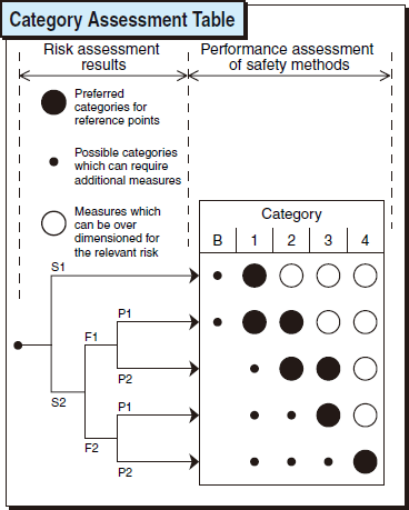
Note: EN954-1 in the table above is the old version. This old version is expected to be valid until December 2009.
The risk caused by failures in safety-related parts of the control system is accessed taking into account the worst degree of injury. S1 is selected if the injury is slight and S2 is selected if it is serious.
Note: EN954-1 in the table above is the old version. This old version is expected to be valid until December 2009.
For example, if a worker must periodically insert his hands between parts of a machine while it is operating to mount and remove machine tool parts, F2 is selected. If the machine is rarely approached, F1 is selected.
Aspects that influence the selection of parameter P include the following:
When a hazardous situation occurs P1 should only be selected if there is realistic chance of avoiding an accident or of significantly reducing its effect. P2 should be selected if there is almost no chance of avoiding the hazard.
Describes risk reduction, which is necessary when designing and constructing safety-related parts of control systems and devices. The categories represent a classification of the control system with respect to their ability to withstand faults and their behavior in the event of a fault.
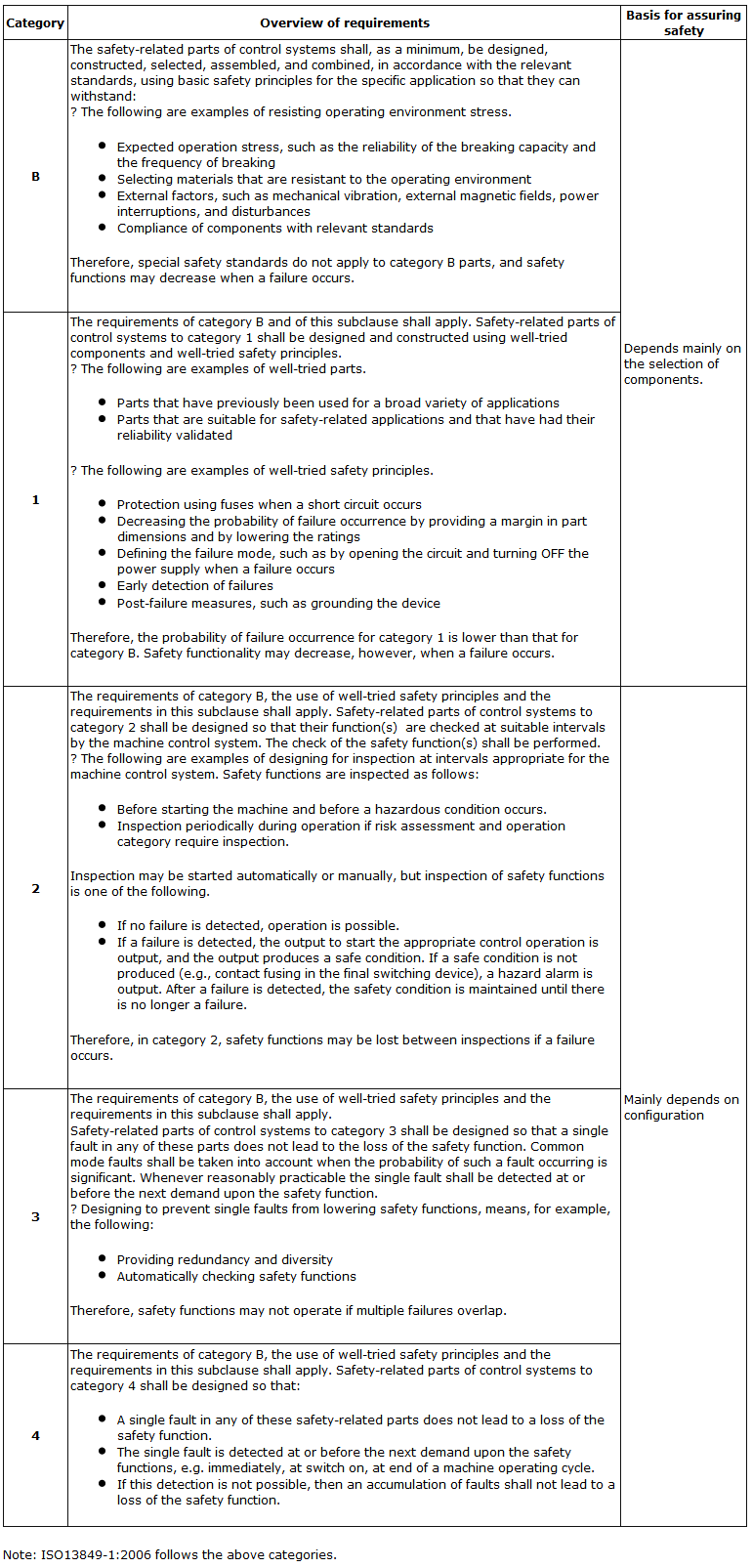
The safety category of safety-related parts is selected based on ISO 13849-1 to attempt to check and reduce the occurrence of hazards associated with the entire machine based on ISO 14121.
Next, analysis and testing is performed to confirm that the safety-related parts conform to the requirements for the safety of the entire machine. Although the analysis is performed using a list of foreseeable faults based on ISO 13849-2 and design criteria based on ISO 13849-1, as an example, the following faults are excluded as examples of ‘fault exception items’.
1. The NC contact of a safety switch with a direct circuit-opening mechanism does not open.
2. The NC and NO contacts of a safety switch with forcibly guided contacts are closed at the same time.
3. A secured cable reliably protected with a cable duct or other means causes a short circuit between wiring due to an external shock.
4. A short circuit occurs in adjacent terminals whose connections are reliably covered with an insulating tube or other means.
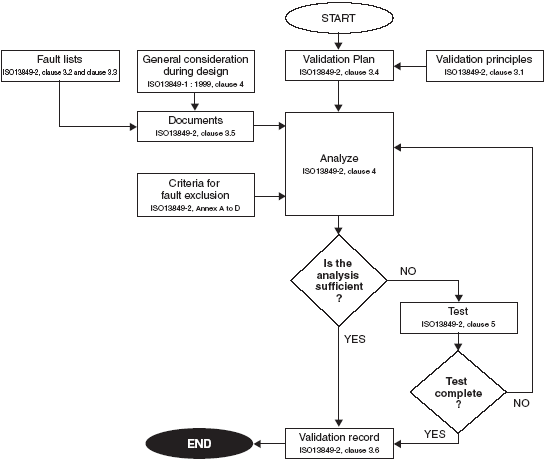
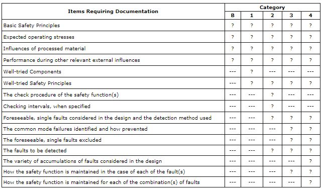
A technical file containing the following information should be recorded:
Items that are required to be documented are shown below, by category (extracted from ISO 13849-2 Table 2)
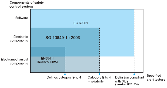
Until now, the ‘category’, i.e. the classification of the architecture (structure) of a safety control system, has been a deterministic theory focused on the composition of hardware.
But as technology advances, electronic components such as transistors, integrated circuits and software based components such as microprocessors were adopted as core elements of safety related control systems.
Since year 2000, work has been underway to define the performance of machine safety control systems in terms of function and reliability rather than component failure modes. This is the concept of “functional safety.” IEC61508, the international standard for safety related electrical and electronic control systems, provides definitions of safety of complicated controls, down to the constituent components level such as designing reliability including life (until a loss of safety function) and programs based upon probability theory.
IEC61508 has a very wide scope of application, so a new standard specifically designed for the machine control systems, IEC62061, was developed to provide for mechanical safety. However, because this standard basically assumes complicated controls, it assumes many safety control system architectures, and individual architecture requires complicated calculation of probability. This is the reason why IEC62061 was not familiar among machine designers who are accustomed to the relatively easy-to-follow definitions of “Categories.”
The latest version of ISO13849-1: 2006 combines the straight forward deterministic features of EN954-1’s Categories with IEC62061’s probabilistic and systematic design considerations (a reliability model). In other words, the revised version of ISO13849-1 selects the architecture models in IEC62061 that match the definitions of the Categories, and applies those reliability models. This version can be called a functional safety standard in its simplified version.
Changes in Risk Estimation Methods
Both methods require estimating risk of hazards at the risk assessment stages.
In estimating risks, EN954-1 evaluated and classified the results of its risk estimations into the risk levels of I to IV.
But the evaluation process did not encompass any notion of targeted performance that safety measures to reduce risks should reach. As a result, safety control system’s structure Categories B to 4 are generally determined directly from the risk graph. When trying to establish a common parameter between persons who perform risk assessment (for example, users) and persons who implement risk reduction (for example, machine designers), the users may not understand the functional differences of safety control system structures from the designer’s viewpoint, and the designer in turn finds it difficult to understand user requirements. Also, the overwhelming majority of risks at actual working sites are minor damage such as suspension of operation for several days, while EN954-1’s risk graph gave more stress for risk estimations to serious damage, and the previous standard did not accurately reflect this aspect.
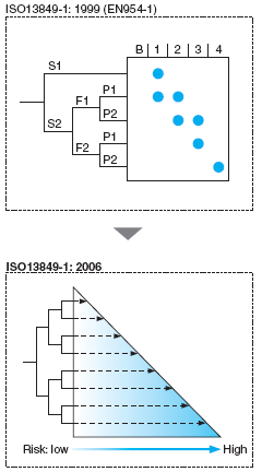
The latest revision in ISO 13849-1: 2006 allows users to determine risk estimations homogeneously and uniquely, and makes risk assessment easier for persons responsible for implementing it.
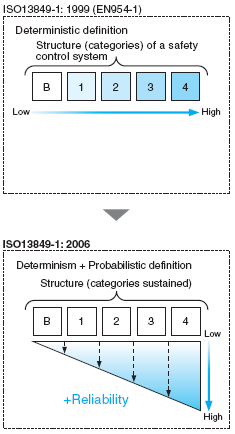
Change in Definitions of Safety Control System's Performance
How should designers reduce risks?
If designers are required to satisfy Category requirements only, once determined safety control system structure will maintain the same level of safety performance.
The question is whether or not this is a correct concept considering that every machine can fail at some future time.
The components comprising the safety control system also will deteriorate and can fail at some future time. It is important to figure out in what mode the system will encounter a failure at such times. When a machine experiences a failure that causes the expected safety function to fail during a period expected by its users, and if the failure is not detected, it is equal to non performance of safety functions. But, definitions only based upon deterministic theory cannot cover such time related elements.
To improve this aspect, the latest revision includes additional features to the previous structure definitions with two-layer structure definitions that enable users to probabilistically evaluate a safety control system’s reliability, including mean time to dangerous failure at the component level and the level of detecting dangerous failure. This allows users to make quantitative evaluation according to how they actually use the machine. This is the core component of the 2006 revision.
Common Indicator Criteria
The revised standard establishes indicators of a safety control system performance level that can be clearly communicated between a person who implements risk assessment and a person who designs a machine.
These indicators are called Performance Level (hereinafter abbreviated as “PL”), and are evaluated using five levels from “a” to “e.” Required performance levels as seen from the standpoint of a person who implements risk assessment are specifically called PLr.
PL, the achieved performance level of a safety control system after risk reduction has been implemented, must be equal to or greater than required Performance Level (PLr).
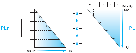
Required Performance Level: PLr
As with the risk graph in EN954-1, a required performance level is evaluated in terms of severity of injury (S), frequency and/or exposure to hazard (F) and possibility of avoiding hazard or limiting harm (P). As a result, the required performance level (PLr) ranging from “a” to “e” is determined depending on the scale of the risk.
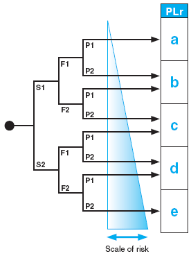
S1: slight (normally reversible injury)
S2: serious (normally irreversible injury or death)
F1: seldom-to-less-often and/or exposure time is short
F2: frequent-to-continuous and/or exposure time is long
P1: possible under specific conditions
P2: scarcely possible
Method to Evaluate Performance Level (PL)
Four parameters are used to evaluate a safety related control system’s performance level (PL).
1. Category
2. MTTFd (Mean Time To Dangerous Failure)
3. DCavg (Average Diagnostic Coverage)
4. CCF (Common Cause Failure)
The Categories refer to the architecture of a safety related control system, and are classified into five categories as defined in the previous version of EN954-1.
MTTFd refers to an average life before the dangerous failure of a component. DC refers to the certainty of detecting failures in the entire system including software. CCF refers to the protection of the entire system from failing due to a common cause. As parameters for reliability, MTTFd and DCavg are determined by formulas, and CCF is determined with a checklist method.
Each of the parameters is classified into levels using standard values: three levels for MTTFd, three levels for DC and two levels for CCF. Performance Levels are evaluated comprehensively in terms of these four parameters.
The following sections show how each of the parameters is calculated.
As described above, when the four parameters are calculated, the PL can be determined from the following graph:
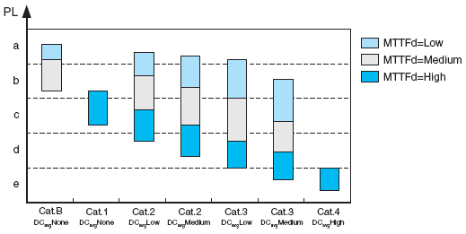
For example, with “Category 4, MTTFd=High, DCavg=High, CCF of 65 points or higher,” then the PL is evaluated as “e”. However, the thresholds in the above graph for MTTFd determination are not easy to locate therefore the below table is provided to give a more simplified view. Either the graph or the table may be used.

An interlocking device is a mechanical or electrical device that can prevent the machine from operating unless certain conditions are met, such as closing a guard. Provisions for interlocking are stipulated in ISO14120 for guards, ISO14119 for interlocking devices associated with guards, and ISO13849-1 for the method that is used to process the signal from an interlocking device and to stop machinery. This section describes interlocking parts linked to guards like safety limit switches and safety door switches in accordance with ISO14119 along with a description of each.
Safety machinery and equipment consist of a control system and an operative system as shown in Fig. 1 Interlocking device. The power control element combines the roles of the control and operative systems, and machine actuators are equipped with safeguards and interlocking devices.
Electricity is supplied to the power control elements only if a safety check signal is sent from the interlock device and an operate command is sent from the control system.
The interlock device is used to send safety check results to the power control elements as shown in the figure below. A safety signal can be sent from a PLC in some cases as long as the PLC does not have a negative impact on the interlock device.
In other words, the interlock device (safety-related part) and the PLC (non safety-related part) are completely independent of each other.
Control systems are divided into safety-related and non-safety-related parts in international safety standards, and they must be constructed so that non-safety-related parts do not have a negative impact on safety-related parts during normal operation or when a malfunction occurs.
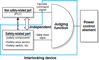
Interlocking devices are classified by type.
Control Interlock
This type of interlocking device inputs a stop command to a control system, like an electromagnetic relay that interrupts or removes the energy supplied to machine actuators.
Power Interlock
This type of interlocking device sends a stop command that directly interrupts or removes the energy supplied to machine actuators. Under the power interlock system, the control system does not intervene between the interlock device and the power supply, but instead the interlock device itself uses a safety switch or some similar measure to control interlocking.
Non-locking Type
The guard can be opened or closed at any time and the interlocking device sends a stop command only if the guard is open.
Locking Type
(1) Unconditional Unlocking:
An operator can unlock the guard at any time with this type of unlocking, but it does have a precondition in that it must take longer to unlock the guard than it does to clear the hazard.
(2) Conditional Unlocking:
The guard can be unlocked under certain conditions, such as when confirming that the hazardous condition has been cleared (e.g. confirming that rotation has stopped).
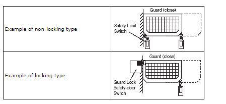
Locking and unlocking types can be classified by the actuating mechanism that is used to apply and release the lock.
Spring Applied, Power Released Type
OMRON uses a mechanical lock/solenoid release method.
Power Applied, Spring Released Type
OMRON uses a solenoid lock/mechanical release method.
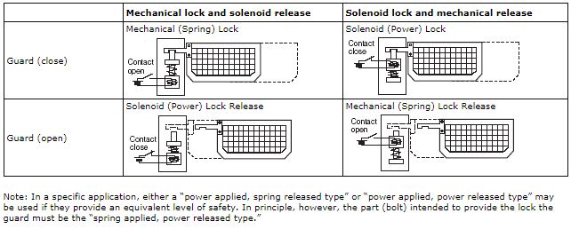
The following items must be considered in the design of interlocking devices that use a safety limit switch or safety door switch.
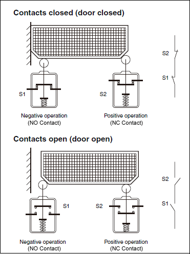
(1) When designing an interlocking device that uses a single mechanically actuated position detector switch, the switch must be actuated in positive operation (positive opening mechanism).
(2) When designing an interlocking device that uses two mechanically actuated position detector switches, one switch must be actuated in positive operation (positive opening mechanism) and the other must be activated in negative operation (negative opening mechanism) notably to avoid common cause failures.
(1) Position detector switches must be tightened and loosened with a tool.
(2) The use of slots for mounting must be limited to initial adjustment and provisions must be made so adjustment will not be needed after the switch is replaced.
(3) Guard movement produced by switch activation must be within a range that will not defeat the safeguard effectiveness.
(4) The mechanical operating range must remain within the specified operating range of the switch.
(5) Switches must not be used as mechanical stops.
(6) Switches must be located, and if necessary protected, to avoid damage from external causes.
(7) Easy access for switch maintenance and inspection must be afforded.
Faults due to common causes must be avoided with redundant designs using one positive-actuated and one negative-actuated switch.
When selecting an interlocking device it is necessary to consider all phases of the interlocking device, including the conditions of use and intended use of the machine, hazards present at the machine and their evaluation, stopping time and access time to the machine, and frequency of access.
An interlocking device with a guard locking must be used when the stopping time is greater than the time it takes a person to reach the danger zone (access time).
(1) For applications requiring frequent access, conduct a risk evaluation and then select an interlocking device that provides the least possible hindrance to the operation of the guard.
(2) For applications using interlocking devices with automatic monitoring, the interlocking device should be used with additional measures, such as conditional guard unlocking, because the frequency of function checks decreases and the probability of an undetected fault occurring increases as the opening frequency decreases.
The following control requirements must be satisfied for interlocking devices for movable guards (ISO 12100-1).
(1) Closing the movable guard enables operation of the machine that was covered by the guard. Closing the movable guard causes the operation to start automatically. At actual startup, restarting can be performed by pressing the start button after all other start conditions are met.
(2) The stop signal for the machine will be output if the guard is opened during operation of a machine that is covered by a guard. In other words, the machine will not be permitted to operate as long as it has not been detected that the guard is closed.
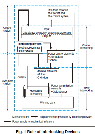
When a fault or disturbance in electrical equipment leads to a hazardous condition and the possibility that the machine as well as the item being processed may be damaged, appropriate steps must be taken to minimize the probability of a hazard. This section uses the safety categories found in EN 60204-1 to describe and illustrate the main procedures to follow to minimize risk in the event of a fault.
The control circuit must comply with the appropriate safe performance level as determined in the risk assessment.
(1) Use of Proven Circuit Techniques and Components
(2) Functional Tests
(3) Provisions of Redundancy
(4) Use of Diversity
(5) Self-monitoring by Safety Relays in Application Circuits
(6) Single-fault Detection
(7) Short-circuit Detection
(8) Emergency Stop
The following examples are typical.
? Basic Circuit Configuration
The following must be taken into consideration when designing safety circuits for a control system.
(1) The relay contacts must open when a coil is not energized.
(2) One line must be grounded on the secondary side of the insulating transformer.
(3) All coils in the safety circuit must be connected directly and as close as possible to the line that connects to the ground line.
(4) The safety circuit must employ a fuse.
The fuse will blow and power to the circuit will cut off if a ground fault occurs on line A. A ground fault will not occur on line B because it is grounded.
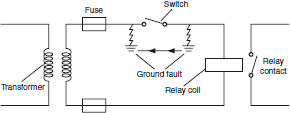
Two ground faults act as a bypass. As a result, the machine may start abruptly or its operation may not be interrupted.
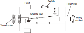
A ground fault causes half the voltage to be applied to the relay coil. As a result, the machine in operation may not be interrupted.
See (8) Emergency Stop for details.
Obtaining safety standards approval means obtaining approval from an independent body such as TÜV.
Parts with safety standards approval display the Safety mark mark.
A fail-safe function ensures safety in the event of fault, break down, or incorrect operation. A fail proof function ensures safety despite human error, fault, or incorrect operation.
Functional tests that ensure safety must be conducted at regular intervals and whenever electric products are started, and they must be conducted either automatically by the control systems of electric products or manually through inspections and tests. If faulty operation occurs, product operation must be suspended until troubleshooting has been completed.
Whole or parts of electric circuits must be redundant (duplicated) to minimize the probability that a malfunction in the circuits will result in a hazard.
The following are examples of redundant electric circuits that employ more than one relay or switch in combination so the circuits will function even if one of the relays or switches fails to operate.
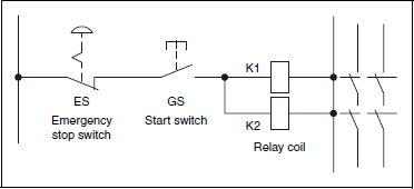
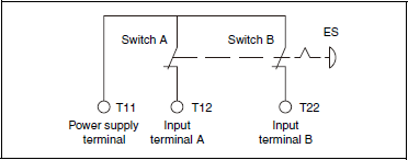
Common malfunctions and the probability of failure in electric products can be reduced if each product uses a variety of control circuits as well as various types of devices and components. The following are examples showing the use of diversity.
1. Safety door with safety components that use a combination of NC and NO contacts.
2. Circuits using control components that are different from each other in type.
3. Redundant combinations of electromechanical and electronic circuits.
When the reset switch is operated, the interface circuits containing safety relays automatically check to see if there are any faults. If there are faults in any circuit, then this safety control circuit will turn OFF power to stop operation.
G9S-301 (24 VDC) - Two Limit Switch Input Channels
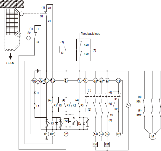
Fault detection 1: Detect closed door switches (K1, K2)
Fault detection 2: Detect fused interface relay and contactor contacts (K3)
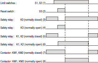
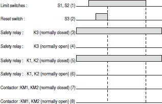
If the normally open contact (8) of the contactor is welded, the normally closed contact (7) will be neutral (not conducting), and no voltage will be applied to the coil of safety relay K3. K3 will not operate, in which case the relay sequence will not operate even if the reset switch (2) is turned ON and power will not be supplied. The auxiliary contacts of the contactor must be mirror contacts.
Programmable controllers are usually used only to monitor safety-related functions, to test functions periodically, or to serve as a backup. Programmable controllers conforming to IEC61131 must be used.
The following example shows a basic circuit with a programmable controller for single-fault detection.
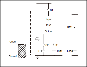
The lead wires of a safety control circuit may be bypassed or short-circuited due to damage caused by force, heat, shock, or acid. Such damage can be detected if the safety control circuit incorporates a short-circuit detecting function that satisfies the following criteria.
(1) The safety circuit must have two input channels that each employ an NC contact.
(2) There must be a potential difference between these channels.
The following example shows a circuit for short-circuit protection.
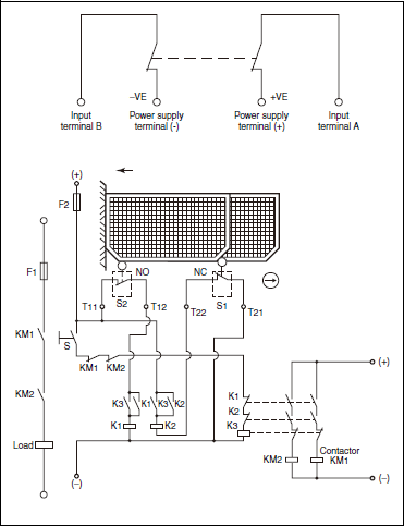
The following items are required for emergency stopping.
(1) Emergency stop equipment must be located at each operator control station and at other locations where the initiation of an emergency stop can be required.
(2) When machinery is divided into several emergency stop zones, emergency stop equipment must be placed where operators can see and access them easily and can operate them without exposure to hazards.
(3) The emergency stop function must have priority over all other functions and operation in any mode.
(4) The emergency stop function must work so that it falls under category 0 or category 1. The choice of category 0 or category 1 must depend on the risk assessment.
Type of Stop Functions
Stop Category 0: Stop category 0 is an uncontrolled stop that is achieved by immediately removing power to the machine actuators
(e.g., directly cutting off the power supply).
Stop Category 1: Stop category 1 is a controlled stop that is achieved by sending a stop command from the control circuit to stop
(e.g., brake) the machine actuators and then removing power to the actuators (e.g., cutting off control circuit power) after the stop is achieved.
Stop Category 2: Stop category 2 stops machine actuators without cutting off the power.
(5) Where several emergency stop devices are provided in a circuit, it must not be possible to restore that circuit until all triggered emergency stop devices have been reset.
(6) Emergency stop equipment must be used as neither an alternative to proper safeguarding measures nor as an alternative for automatic safety devices, but they may be used as a back-up measure.
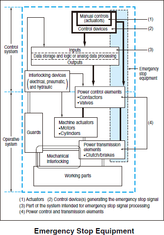
The functional and design-related principles of emergency stop buttons, pull-cord switches, foot pedals, and other emergency stop devices are defined in ISO 13850. Devices built in accordance with ISO 13850 are suitable for emergency stop applications. Their general design is as shown below.
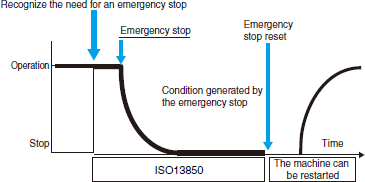
The requirements for the emergency stop function as stipulated in IEC 60204-1 are as follows:
The relevant standards divide applications into numerous stop categories. The selection of the appropriate category must be made depending on a risk assessment of the machine involved.
Basic safety is broadly classified into the following categories.
(1) Machines and equipment will not start until it is safe to do so.
(2) Machinery will be stopped whenever a hazardous condition is detected.
In order to maintain a safe environment, measures must be employed on one level to detect operators entering or present in a hazardous area and on another level to eliminate hazardous conditions.
The safety requirements for presence detection, such as those shown below, are defined by the standards and guidelines of each country.
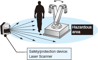
The sensor detects the presence of a worker in dangerous environments.
Presence detection methods are broadly classified into the following categories.
Features: Relative freedom in defining protected areas.
Features: Excellent environmental resistance
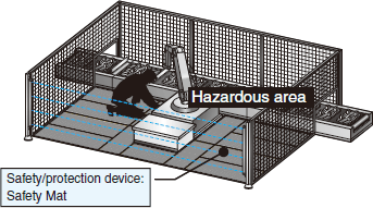
When an operator enters a hazardous area, the machine in the area must come to a complete stop before that operator reaches the hazardous part of the machine. Safe distance refers to the minimum calculated distance that the protective device must be installed from the hazardous part of the machine.
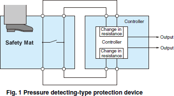
As shown in Fig. 1, two plates inside the Safety Mat make contact when an operator steps on the Mat. A Controller detects the contact and generates an output.
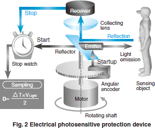
As shown in Fig. 2, the laser scanner emits a beam that is reflected by surrounding objects. It calculates the distance to the object from the time that it takes to receive the reflected light.
One way to prevent operators from approaching hazardous areas too closely when conditions are hazardous is to install two-hand controllers at specified locations.
The guidelines for designing Two-hand Controllers are given in ISO13851. The major safety requirements for Controller design are listed there under Functional Aspects and Principles of Design for Two-hand Controllers.
Note: Conduct actual designing in compliance with the detailed stipulations of ISO13851.
The characteristics that must be provided are categorized by type into Type I, Type II, and Type III categories. The major characteristics listed here are Type III characteristics used in Category 3 and 4, as determined by risk assessment.
(1) Two hands must be used together to start up the machine.
(2) Two input signals are required to produce an output signal.
(3) The output signal must turn OFF if either or both input signals turn OFF.
(4) Both input signals must be turned OFF before the output signal is restarted.
(5) Both input signals must turn ON within 0.5 s to enable synchronous startup output.
(6) Preventing inadvertent startup and disable prevention: Refer to Article 2.
The two startup switches must be at least 260 mm (inside dimensions laterally) apart.
Note: A shield must be installed between the two startup switches. This does not apply to applications where disable prevention is possible.
The two startup switches must be at least 550 mm (inside dimensions laterally) apart.
Note: A shield must be installed between the two startup switches. This does not apply to applications where disable prevention is possible.
Install a cover or enclosure
Install the startup switches at least 1,100 mm off the floor or from the operating level to prevent operators from employing disable prevention with one hand and another part of the body (e.g. knees, hips, etc.).
Note: Safe Distance The safe distance from the startup switches to the hazardous area must be calculated using factors such as hand and arm speed, response time of the startup switches, and maximum time required to eliminate a hazard according to ISO13855.
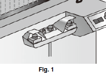
Fig. 1 shows a typical example of a Two-hand Controller according to Articles 2.1 to 2.3.
The part of "Circuit Diagrams" includes shows an example of a G9SA-TH301 Safety Relay Unit connected to a Two-hand Controller.
The part of "Circuit Diagrams" includes shows an example of an F3SX Safety Controller, F3SN-A Safety Light Curtain, and A22 Pushbutton Switch connected to a Two-hand Controller for the caulking machine shown below.
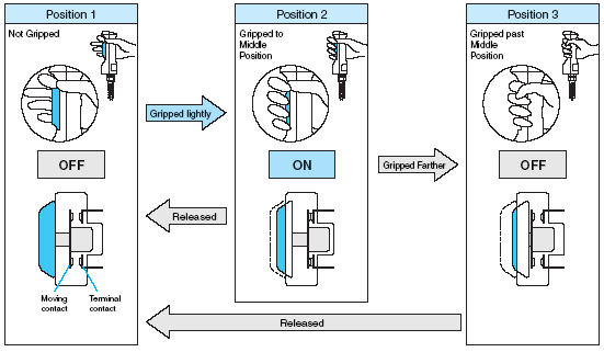
An enabling switch is a safety component used so that workers can avoid unexpected machine movement when performing non-scheduled maintenance work or other non-scheduled operations in hazardous areas, such as those inside safety fences.
When a worker is using a hand-held console with operation switches to teach a robot, retool, or perform maintenance, unexpected movement of a hazard can result in a hazardous state. When this occurs, it's impossible to predict whether the operator will instinctively release the console or will grip it with force. A normal switch thus does not turn OFF when excessive force is applied, which may result in a worker accident.
With an Enabling Switch, machines or robots can be controlled only when the switch is gripped lightly to the middle position. If the switch is gripped with force past the middle position or if the switch is released, the machine or robot will be shut OFF, disabling operation.
Enabling Switches are normally used built into teaching pendants, grip switches, and other hand-held controls. They can be combined with safety circuits built with Safety Relay Units and other devices to ensure safety.
Enabling Switches operate through three positions: OFF - ON - OFF. They are OFF when not pressed, ON when pressed to the middle position, and then OFF again when pressed past the middle position.
Until recently, there were no means to confirm the safety of technologies such as complex electronic components or software, which made it difficult to apply them safely. Demands have increased, however, by companies that want greater safety in the use of various devices. This has led to the concept of functional safety, which is a method of confirming safety by providing the reliability that electronic equipment and programmable devices used in safety equipment will operate properly when the safety related demand is given. Reliability here refers to "lowering human risk to the level of socially tolerable risk." This includes the following factors:
1. Periodic confirmation tests are conducted, showing that there are no latent hazards.
For example, a failure is detected in self-diagnosis and a safe state is achieved.
2. Reliability with respect to deterioration and lifetime of assembly components.
For example, the probability of a hazardous failure is determined for each part.
3. System reliability.
It is confirmed that protection against one type of hazard will not invite a different type of hazard.
IEC 61508, which was issued in 1998, is representative of common standards for functional safety. IEC 61508 is further divided into seven detailed standards for individual fields of application. Standards for industrial machinery are stipulated in IEC 62061. For detailed information, refer to these standards.
In the above standards, the SIL (Safety Integrity Level) is defined as parameters that specify the requirements of safety functions. In the area of machinery, it has been decided to coordinate the SIL with the performance level (PL) defined by ISO 13849-1,2006.

The required SIL (Safety Integrity Level) is greatly determined by whether the operation demand is low or high/continuous.
SIL Required of Safety-related Controls in Low Demand Mode (for Example, Safety-related Controls That Operate Only for a Short Time When There Is Demand, Such as ABS on Cars)
Example: If risk assessment determined that SIL2 is suitable, the TFM that needs to be achieved by the related safety controls would be 10-2 < TFM = 10-3.

SIL Required of Safety-related Controls in High or Continuous Demand Mode (for Example, Safety-related Controls That Operate Continuously or Frequently over a Long Period of Time, Such as a Pacemaker)
Example: If risk assessment determined that SIL2 is suitable, the TFM that needs to be achieved by the related safety controls would be 10-6 < TFM = 10-7.
Note: TFM (Target Failure Measure)

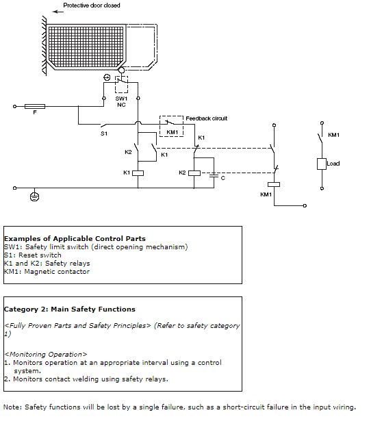
This part provides control circuit (safety circuit) examples grouped by category. These circuits are made up of electric interlocking mechanisms that incorporate protective door and safety switches.
Note 1:
These interlock mechanisms are only part of the safety systems of machines. An appropriate system suitable to the safety of the overall machine must be designed, selected, and constructed after evaluating the risks in the work environment as well as hazardous conditions, such as the frequency of access to hazardous areas and the time required to ensure the hazard has been removed.
Note 2:
Circuit Examples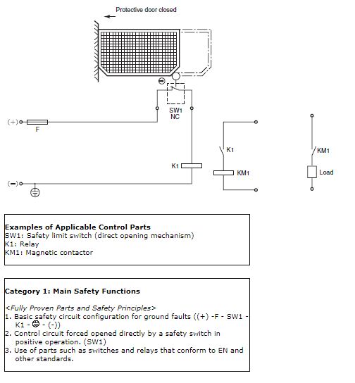
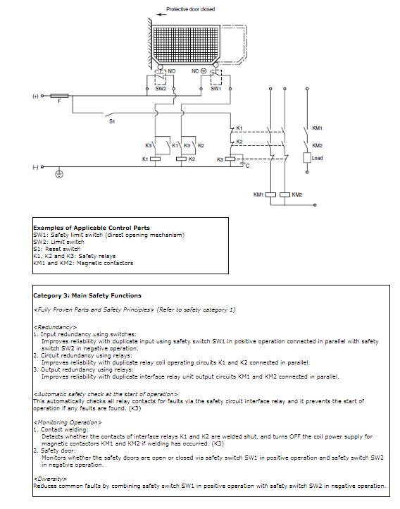
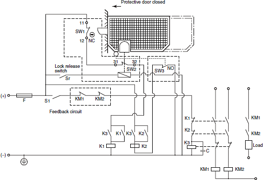
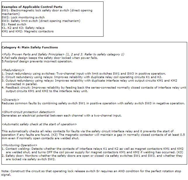
The international standards are described below, along with the European EN number and the new JIS number for each set of standards.

This part of these standards defines the basic concepts of machinery safety and stipulates safety design procedures.
(1) Machinery hazards are classified as follows: Mechanical hazards, electrical hazards, thermal hazards, hazards generated by noise, hazards generated by vibrations, hazards generated by radiation, hazards generated by materials and substances, and hazards generated by neglecting ergonomic principles in machine design.
(2) Identify the preceding hazards and apply safety design procedures to reduce risks.
Step 1: Specify the operating range of the machine.
Step 2: Identify the hazards and assess the risks.
Step 3: Remove hazards and reduce risks as much as possible.
Step 4: Design guards, safety equipment, and other safeguards against any residual risks.
Step 5: Inform and warn users about any residual risks.

This part of these standards describes the safety design procedures stipulated in part 1 in greater detail.
This part of these standards takes step 3 (Remove hazards and reduce risks as much as possible.), step 4 (Design guards, safety equipment and other safeguards against any residual risks.), and step 5 (Inform and warn users about any residual risks.) given in part 1 and describes them in greater detail.

These standards pertain to risk assessment in the safety design procedures described in ISO12100-1.
Assess risk is performed using the following systematic methodology:
A) Determine how the machinery will be used.
B) Check foreseeable hazards.
C) Identify risk elements based on hazardous events.
D) Assess the risk and design accordingly to reduce the risk.

These standards apply to control systems where safety is a concern.
(1) These standards consider the anticipated degree of injury (light to serious) and the probability of injury (rare to common) in determining the hazard level of machinery.
(2) These standards classify hazard levels in five safety categories and stipulates safety functions that control systems should have in every category.

Regarding the verification of the applicability of claims in relation to ISO13849-1 (EN954-1) categories.
In order to verify applicability to the category claims, the following should be specified:
(1) Guidelines for validity testing and inspections
(2) General considerations at time of design
(3) List of failures and failure exclusion criteria
(4) Test and test results or report

This part of these standards applies to electrical equipment with a rated power supply voltage of less than 1,000 VAC or 1,500 VDC between lines or a rated frequency of less than 200 Hz.
This part of these standards stipulates all elements required in electrical equipment for machines including the control circuits, functions, devices, safety measures, and technical documents related to the installation, operation, and maintenance of electrical and electronic equipment in machines.

This standard sets out specific requirements regarding visual, audio and tactile methods for providing safety related information to operators and those that may be placed in dangerous situations.
(1) Separate signals into passive and active
(2) Visual spectrum, brightness, and contrast ratio
(3) Meaning of colors and the shape of markings, and examples of forms that can be discerned by touch alone
(4) Operating switch symbols
(5) Shape, color and dimensions of safety markings (Prohibitions, warnings, information etc.)

This standard sets out the identification of machines, and markings to ensure safe use and the reduction of danger from incorrect connections.
(1) Regulations regarding manufacturer information (manufacturer name, address etc.), and rating information (power supply range, maximum speed etc.)
(2) Regulations regarding necessary markings such as for AC, DC and grounding etc.

Specifies safety issues for actuators that are operated by hand or by human control.
(1) Set up away from dangers, and avoid ambiguous operations. Also, be sure that operation does not create alternative risks.
(2) Design to increase the clockwise rotation of handles and lifting action for levers, so that the operator is better aware of the resulting operation.
(3) Two-handed operating controls and enabling devices where necessary.

This standard specifies those matters applicable to the machinery portion of the industry as included in the IEC 61508 Series Functional Safety Standards.
This standard applies to the design and verification of safety related control systems that use electric, electronic, or programmable electronic control systems.
Standards, including the following, for the allotment of SIL (Safety Integrity Level) and in order to achieve the allotted SIL, for safety functions performed by safety control systems.
(1) Functional safety management
(2) Create specifications for safety controls
(3) Control system design
(4) User information (Manual)
(5) Check Validity

These standards stipulate general design and selection principles for equipment that uses interlocking devices for safety.
(1) There are two types of interlocking devices: those with and those without a guard lock.
(2) The guard must not allow machinery to operate until it is closed and it sends a stop command if it is open.

This part of these standards applies to control circuit devices and switching elements that are produced to control, signal, and interlock switching and control devices. It applies to control circuits with a maximum rated voltage of 600 VDC or 1,000 VAC (a maximum frequency of 1,000 Hz).
(1) This part of these standards consists of Chapter 1: General Requirements, Chapter 2: Special Requirements for Indicators, and Chapter 3: Special Requirements for Positive Opening.
(2) It contains provisions such as switching capacity, temperature rise, terminal strength, protective structures, and positive opening.

An IEC 60947-5 Series standard that stipulates 3-position enabling switches, for enable devices under the IEN60204-1 standard. This does not apply to devices that employ teaching pendants or grip switches etc., but only to those devices with built-in enable switches.
(1) Stipulates electrical properties such as withstand voltage and insulation, and operating characteristics for operating stroke and load etc.
(2) The 3-position enabling switch verification mark has been changed.

These standards stipulate safety requirements related to the design and selection of two-hand control devices.
(1) Stipulates dimensions for prevention of defect.
(2) Output signal shall be designated only when both control actuating devices are actuated less than or equal to 0.5 s.
(3) Classify devices by type (type I, II, IIIA, IIIB and IIIC) and risk assessment results as the basis for selecting devices.

These are German labor safety standards that were enacted to prevent industrial accidents. They apply to testing on positive opening position detector switches that are installed for safety.
(1) Limit and door switches are classified in two categories according to function.
(2) The switches must have a positive opening mechanism, a mechanical service life of 1,000,000 operations, and an enclosure rating of IP54, and must not operate with any tool except a special operation key.

These are also German labor safety standards. They apply only to devices that have a lock monitoring mechanism in door switches that use a key lock for safety.
(1) The switches must use a mechanism like a solenoid for locking and unlocking.
(2) They must have a locking strength and positive opening mechanism, a mechanical service life of 1,000,000 operations, and an enclosure rating of IP54, and must not operate with a tool other than a special operation key.

These standards stipulate principles used to design emergency stop devices.
(1) Devices must have a positive opening mechanism.
(2) Devices must have a latching mechanism.
(3) The operative parts must be structured to allow easy access to the mushroom-shaped pushbuttons, wires, and ropes.
(4) The operative parts must be red on a yellow background.

These standards apply to devices, such as safety sensors/safety light curtains, that detect the presence of workers electrically and output a control signal for their protection. They stipulate items like fault detection performance, software design policy, heat resistance performance, EMC performance, vibration and shock performance, indicator colors, labeling details, and the content of operating manuals.
(1) Electro-sensitive protective equipment (ESPE) is classified as either type 4, which complies with category 4 requirements in EN954-1, or type 2, which complies with category 2 requirements in that same standard.
(2) The provisions in these standards stipulate that equipment displays the fault mode for electronic components in the equipment and they demonstrate that safety characteristics for the type of equipment are maintained in all fault modes.

This part of these standards applies to the type of ESPE protective equipment that in principle detect emitted or received light. They stipulate items such as detection performance for the minimum size object detected, effective aperture angle, extraneous light resistance performance, and mutual interference resistance performance.
(1) Directional angles are stipulated separately for type 4 and type 2 according to the distance between the emitter and receiver.
(2) Conditions that maintain ordinary operation and conditions that permit incorrect operation safely are stipulated for all extraneous light sources.

This part of these standards applies to electro-sensitive protective equipment that diffuse or reflect light. They stipulate items such as detection performance for the detection range, allowable errors, response time, detection capacity, resistance to extraneous light, and reflective detection capability as well as the influence of background interference.
(1) Only stipulated for Type 3. (not specified for types 1, 2 and 4)
(2) Conditions that maintain ordinary operation and conditions that permit incorrect operation safely are stipulated for all extraneous light sources.

These standards stipulate the minimum distance that must be provided between hazardous parts of machinery and protective equipment. Referred to as the safe distance, this distance is calculated from the worker entry direction, protective equipment response time, machine response time, and minimum object size detectable by the protective equipment.
(1) These standards apply when individual machine standards do not prescribe the method used to calculate safe distance.
(2) Protective equipment must be selected with a detection performance level capable of maintaining a safe distance so machines can be stopped before they pose a hazard to workers.

These standards apply to control circuit relays that are installed for safety and its provisions are for self-monitoring relays that have a forced guided mechanism that prevents normally open and closed contacts from operating simultaneously.
(1) If a normally open contact of a relay with forcibly guided (linked) contact is welded shut, the coil switches OFF and all normally closed contacts must maintain a gap of at least 0.5 mm. Even if a normally closed contact is welded shut, the coil switches ON and all normally open contacts must maintain a gap of at least 0.5 mm.
(2) Ideally, contact load switching must comply with the AC-15 (AC electromagnetic load) and DC-13 (DC electromagnetic load) utilization categories.
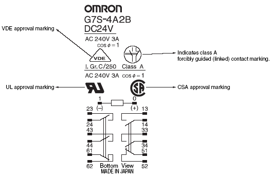
(3) The forced guide contact mark may be used on all class A relays (all relays with forcibly guided (linked) contacts).
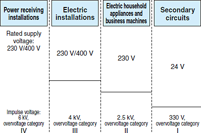
Pollution degree is the most important factor in deciding clearances (determined by the pollution degree and overvoltage categories) as well as creepage (determined by the pollution degree and CTI value), and it is classified into four degrees depending on the air pollution of the equipment used.

The overvoltage category classifies overvoltages into categories I, II, III and IV depending on whether the rated voltage is the rated impulse voltage or the rated voltage of the equipment as shown in the table below. Rated impulse voltage levels are set individually with respect to the rated voltages as shown in the figure below. The overvoltage category is one of the factors that decide spacing (determined by the overvoltage category and pollution degree).

Measurement of CTI Value
(The value is measured using method A from the CTI/PTI value measurement methods stipulated in IEC60112.)
The CTI value of an insulation material is the maximum possible voltage that does not cause tracking when 50 drops of 0.1% ammonium chloride solution are dripped onto the material at a rate of 30 seconds per drop.
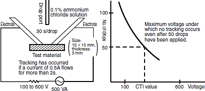
Materials Classified with CTI Value Range (IEC60664-1)
Group I: CTI value greater than 600
Group II: CTI value greater than 400 but less than 600
Group IIIa: CTI value greater than 175 but less than 400
Group IIIb: CTI value greater than 100 but less than 175
Standard limit switches use group IIIa or better insulation material
Materials that conform to CTI values of 175, 250, 300, 375 and 500 are called PTI-175, PTI-250, PTI-300, PTI-375 and PTI-500 respectively. IEC60335 and IEC60065 stipulate that electric household appliances and consumer electronic appliances such as TVs, VTRs and radios must use PTI-175 or PTI-250 materials.
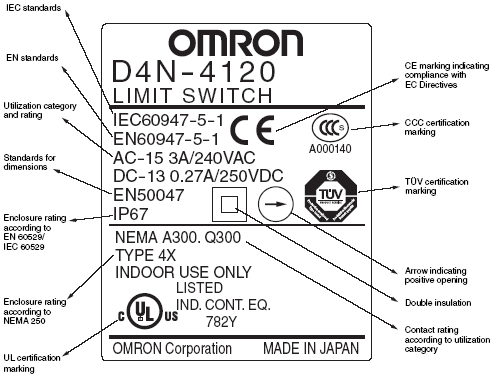
The rated operational voltage (Ue) of equipment is the voltage applied to equipment, and is combined with the rated operational current (Ie) as references for utilization categories (i.e., AC-15).
The rated operational current (Ie) is the current applied to equipment.
The conventional free air thermal current (Ith) is the maximum test current used by the manufacturer for temperature-rise tests on unenclosed products in free air.
The conventional enclosed thermal current (Ithe) is the test current stated by the manufacturer to be used for temperature-rise tests on products mounted in a specified enclosure. The value of the current must be greater than that of the rated operational current (Ie).
The rated impulse withstand voltage (Uimp) is the peak value for an impulse voltage of prescribed form which equipment is capable of withstanding without failure and to which clearance values are referred.
The rated insulation voltage (Ui) is the maximum operating voltage that can be withstood without damage. It is the reference voltage for dielectric strength tests and creepage distance for insulation material. The maximum value of the rated insulation voltage (Ui) must be greater than that of the rated operating voltage.
The switching overvoltage is the maximum reverse voltage that occurs with load switching. It must never exceed the rated input withstand voltage (Uimp).
The rated conditional short-circuit current is the current stated by the manufacturer that a product can withstand provided the product is protected by a device (10-A fuse model gI or gG/IEC60269 for the D4BL) that is designated by the manufacturer under conditions specified by related product standards.
A600 is the contact rating for a utilized category that expresses the following:

Utilization Category for Switching Elements (Classified by switching path and current.)

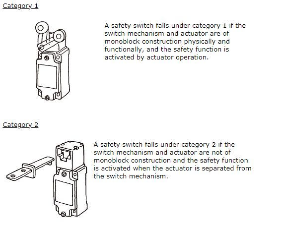
According to GS-ET-15, safety switches equipped with positive opening mechanisms are classified in category 1 or 2 according to functional differences.
Type 4 safety devices satisfy category 4 requirements prescribed in EN954-1.
ESPE equipment electrically detects people and outputs a control signal for their protection.
AOPD protective devices are electro-sensitive protective devices that operate on the principle of detection by emitted and received light.
The protective height is the range within which objects can be detected. The height is the length from the first optical beam to the last optical beam.
The response time is the maximum amount of time it takes from the moment someone is detected in the detection zone until the output turns OFF. The time it takes to turn output ON again once it goes off is also listed in catalog specifications mainly for system design.
The muting function temporarily disables the detection function. In that case, the protective equipment remains ON regardless of whether someone enters the detection zone or not. F3SN-A models do not have the muting function. The muting function can be added by connecting the F3SP-U2P Muting Controller. The muting function can also be added to the F3SJ-A by mounting the F39-CN6 Muting Cap.
A test rod is an opaque rod equivalent to the smallest detectable object. It is an accessory that is used to check the detection performance of area sensors.
The safety zone is the minimum distance that must be allowed from hazardous parts of machinery to the protection equipment. It is prescribed so that machinery will turn OFF before someone entering the detection zone of the protection equipment reaches hazardous parts of the machinery.
The imaginal line that top beam and bottom beam of light curtain is connected. It is the reference line that is used to measure the Safety distance from hazardous parts of machinery to the light curtain. The axis is marked by the light beam axis line mark on the indicator section of F3SN-A models.
The effective aperture angle is the angle to which area sensors must be rotated to switch the output from ON to OFF. Measurements can be taken in two directions with lateral rotation as long as the rotation follows the axis formed by the light beams.
A lock out disables normal operation and it occurs when the output is forced OFF. When F3SJ/F3SN control output remains OFF because self-diagnosis results have determined that operation cannot be resumed as a result of a fault, this is called a lock out.
Emitter:

Receiver:

This part provides control circuit (safety circuit) examples grouped by category. These circuits are made up of electric interlocking mechanisms that incorporate protective door and safety switches.
Note 1:
These interlock mechanisms are only part of the safety systems of machines. An appropriate system suitable to the safety of the overall machine must be designed, selected, and constructed after evaluating the risks in the work environment as well as hazardous conditions, such as the frequency of access to hazardous areas and the time required to ensure the hazard has been removed.
Note 2:
Circuit Examples


The international standards are described below, along with the European EN number and the new JIS number for each set of standards.

This part of these standards defines the basic concepts of machinery safety and stipulates safety design procedures.
(1) Machinery hazards are classified as follows: Mechanical hazards, electrical hazards, thermal hazards, hazards generated by noise, hazards generated by vibrations, hazards generated by radiation, hazards generated by materials and substances, and hazards generated by neglecting ergonomic principles in machine design.
(2) Identify the preceding hazards and apply safety design procedures to reduce risks.
Step 1: Specify the operating range of the machine.
Step 2: Identify the hazards and assess the risks.
Step 3: Remove hazards and reduce risks as much as possible.
Step 4: Design guards, safety equipment, and other safeguards against any residual risks.
Step 5: Inform and warn users about any residual risks.

This part of these standards describes the safety design procedures stipulated in part 1 in greater detail.
This part of these standards takes step 3 (Remove hazards and reduce risks as much as possible.), step 4 (Design guards, safety equipment and other safeguards against any residual risks.), and step 5 (Inform and warn users about any residual risks.) given in part 1 and describes them in greater detail.

These standards pertain to risk assessment in the safety design procedures described in ISO12100-1.
Assess risk is performed using the following systematic methodology:
A) Determine how the machinery will be used.
B) Check foreseeable hazards.
C) Identify risk elements based on hazardous events.
D) Assess the risk and design accordingly to reduce the risk.

These standards apply to control systems where safety is a concern.
(1) These standards consider the anticipated degree of injury (light to serious) and the probability of injury (rare to common) in determining the hazard level of machinery.
(2) These standards classify hazard levels in five safety categories and stipulates safety functions that control systems should have in every category.

Regarding the verification of the applicability of claims in relation to ISO13849-1 (EN954-1) categories.
In order to verify applicability to the category claims, the following should be specified:
(1) Guidelines for validity testing and inspections
(2) General considerations at time of design
(3) List of failures and failure exclusion criteria
(4) Test and test results or report

This part of these standards applies to electrical equipment with a rated power supply voltage of less than 1,000 VAC or 1,500 VDC between lines or a rated frequency of less than 200 Hz.
This part of these standards stipulates all elements required in electrical equipment for machines including the control circuits, functions, devices, safety measures, and technical documents related to the installation, operation, and maintenance of electrical and electronic equipment in machines.

This standard sets out specific requirements regarding visual, audio and tactile methods for providing safety related information to operators and those that may be placed in dangerous situations.
(1) Separate signals into passive and active
(2) Visual spectrum, brightness, and contrast ratio
(3) Meaning of colors and the shape of markings, and examples of forms that can be discerned by touch alone
(4) Operating switch symbols
(5) Shape, color and dimensions of safety markings (Prohibitions, warnings, information etc.)

This standard sets out the identification of machines, and markings to ensure safe use and the reduction of danger from incorrect connections.
(1) Regulations regarding manufacturer information (manufacturer name, address etc.), and rating information (power supply range, maximum speed etc.)
(2) Regulations regarding necessary markings such as for AC, DC and grounding etc.

Specifies safety issues for actuators that are operated by hand or by human control.
(1) Set up away from dangers, and avoid ambiguous operations. Also, be sure that operation does not create alternative risks.
(2) Design to increase the clockwise rotation of handles and lifting action for levers, so that the operator is better aware of the resulting operation.
(3) Two-handed operating controls and enabling devices where necessary.

This standard specifies those matters applicable to the machinery portion of the industry as included in the IEC 61508 Series Functional Safety Standards.
This standard applies to the design and verification of safety related control systems that use electric, electronic, or programmable electronic control systems.
Standards, including the following, for the allotment of SIL (Safety Integrity Level) and in order to achieve the allotted SIL, for safety functions performed by safety control systems.
(1) Functional safety management
(2) Create specifications for safety controls
(3) Control system design
(4) User information (Manual)
(5) Check Validity

These standards stipulate general design and selection principles for equipment that uses interlocking devices for safety.
(1) There are two types of interlocking devices: those with and those without a guard lock.
(2) The guard must not allow machinery to operate until it is closed and it sends a stop command if it is open.

This part of these standards applies to control circuit devices and switching elements that are produced to control, signal, and interlock switching and control devices. It applies to control circuits with a maximum rated voltage of 600 VDC or 1,000 VAC (a maximum frequency of 1,000 Hz).
(1) This part of these standards consists of Chapter 1: General Requirements, Chapter 2: Special Requirements for Indicators, and Chapter 3: Special Requirements for Positive Opening.
(2) It contains provisions such as switching capacity, temperature rise, terminal strength, protective structures, and positive opening.

An IEC 60947-5 Series standard that stipulates 3-position enabling switches, for enable devices under the IEN60204-1 standard. This does not apply to devices that employ teaching pendants or grip switches etc., but only to those devices with built-in enable switches.
(1) Stipulates electrical properties such as withstand voltage and insulation, and operating characteristics for operating stroke and load etc.
(2) The 3-position enabling switch verification mark has been changed.

These standards stipulate safety requirements related to the design and selection of two-hand control devices.
(1) Stipulates dimensions for prevention of defect.
(2) Output signal shall be designated only when both control actuating devices are actuated less than or equal to 0.5 s.
(3) Classify devices by type (type I, II, IIIA, IIIB and IIIC) and risk assessment results as the basis for selecting devices.

These are German labor safety standards that were enacted to prevent industrial accidents. They apply to testing on positive opening position detector switches that are installed for safety.
(1) Limit and door switches are classified in two categories according to function.
(2) The switches must have a positive opening mechanism, a mechanical service life of 1,000,000 operations, and an enclosure rating of IP54, and must not operate with any tool except a special operation key.

These are also German labor safety standards. They apply only to devices that have a lock monitoring mechanism in door switches that use a key lock for safety.
(1) The switches must use a mechanism like a solenoid for locking and unlocking.
(2) They must have a locking strength and positive opening mechanism, a mechanical service life of 1,000,000 operations, and an enclosure rating of IP54, and must not operate with a tool other than a special operation key.

These standards stipulate principles used to design emergency stop devices.
(1) Devices must have a positive opening mechanism.
(2) Devices must have a latching mechanism.
(3) The operative parts must be structured to allow easy access to the mushroom-shaped pushbuttons, wires, and ropes.
(4) The operative parts must be red on a yellow background.

These standards apply to devices, such as safety sensors/safety light curtains, that detect the presence of workers electrically and output a control signal for their protection. They stipulate items like fault detection performance, software design policy, heat resistance performance, EMC performance, vibration and shock performance, indicator colors, labeling details, and the content of operating manuals.
(1) Electro-sensitive protective equipment (ESPE) is classified as either type 4, which complies with category 4 requirements in EN954-1, or type 2, which complies with category 2 requirements in that same standard.
(2) The provisions in these standards stipulate that equipment displays the fault mode for electronic components in the equipment and they demonstrate that safety characteristics for the type of equipment are maintained in all fault modes.

This part of these standards applies to the type of ESPE protective equipment that in principle detect emitted or received light. They stipulate items such as detection performance for the minimum size object detected, effective aperture angle, extraneous light resistance performance, and mutual interference resistance performance.
(1) Directional angles are stipulated separately for type 4 and type 2 according to the distance between the emitter and receiver.
(2) Conditions that maintain ordinary operation and conditions that permit incorrect operation safely are stipulated for all extraneous light sources.

This part of these standards applies to electro-sensitive protective equipment that diffuse or reflect light. They stipulate items such as detection performance for the detection range, allowable errors, response time, detection capacity, resistance to extraneous light, and reflective detection capability as well as the influence of background interference.
(1) Only stipulated for Type 3. (not specified for types 1, 2 and 4)
(2) Conditions that maintain ordinary operation and conditions that permit incorrect operation safely are stipulated for all extraneous light sources.

These standards stipulate the minimum distance that must be provided between hazardous parts of machinery and protective equipment. Referred to as the safe distance, this distance is calculated from the worker entry direction, protective equipment response time, machine response time, and minimum object size detectable by the protective equipment.
(1) These standards apply when individual machine standards do not prescribe the method used to calculate safe distance.
(2) Protective equipment must be selected with a detection performance level capable of maintaining a safe distance so machines can be stopped before they pose a hazard to workers.

These standards apply to control circuit relays that are installed for safety and its provisions are for self-monitoring relays that have a forced guided mechanism that prevents normally open and closed contacts from operating simultaneously.
(1) If a normally open contact of a relay with forcibly guided (linked) contact is welded shut, the coil switches OFF and all normally closed contacts must maintain a gap of at least 0.5 mm. Even if a normally closed contact is welded shut, the coil switches ON and all normally open contacts must maintain a gap of at least 0.5 mm.
(2) Ideally, contact load switching must comply with the AC-15 (AC electromagnetic load) and DC-13 (DC electromagnetic load) utilization categories.
(3) The forced guide contact mark may be used on all class A relays (all relays with forcibly guided (linked) contacts).
Pollution degree is the most important factor in deciding clearances (determined by the pollution degree and overvoltage categories) as well as creepage (determined by the pollution degree and CTI value), and it is classified into four degrees depending on the air pollution of the equipment used.

The overvoltage category classifies overvoltages into categories I, II, III and IV depending on whether the rated voltage is the rated impulse voltage or the rated voltage of the equipment as shown in the table below. Rated impulse voltage levels are set individually with respect to the rated voltages as shown in the figure below. The overvoltage category is one of the factors that decide spacing (determined by the overvoltage category and pollution degree).


Measurement of CTI Value
(The value is measured using method A from the CTI/PTI value measurement methods stipulated in IEC60112.)
The CTI value of an insulation material is the maximum possible voltage that does not cause tracking when 50 drops of 0.1% ammonium chloride solution are dripped onto the material at a rate of 30 seconds per drop.

Materials Classified with CTI Value Range (IEC60664-1)
Group I: CTI value greater than 600
Group II: CTI value greater than 400 but less than 600
Group IIIa: CTI value greater than 175 but less than 400
Group IIIb: CTI value greater than 100 but less than 175
Standard limit switches use group IIIa or better insulation material
Materials that conform to CTI values of 175, 250, 300, 375 and 500 are called PTI-175, PTI-250, PTI-300, PTI-375 and PTI-500 respectively. IEC60335 and IEC60065 stipulate that electric household appliances and consumer electronic appliances such as TVs, VTRs and radios must use PTI-175 or PTI-250 materials.
The rated operational voltage (Ue) of equipment is the voltage applied to equipment, and is combined with the rated operational current (Ie) as references for utilization categories (i.e., AC-15).
The rated operational current (Ie) is the current applied to equipment.
The conventional free air thermal current (Ith) is the maximum test current used by the manufacturer for temperature-rise tests on unenclosed products in free air.
The conventional enclosed thermal current (Ithe) is the test current stated by the manufacturer to be used for temperature-rise tests on products mounted in a specified enclosure. The value of the current must be greater than that of the rated operational current (Ie).
The rated impulse withstand voltage (Uimp) is the peak value for an impulse voltage of prescribed form which equipment is capable of withstanding without failure and to which clearance values are referred.
The rated insulation voltage (Ui) is the maximum operating voltage that can be withstood without damage. It is the reference voltage for dielectric strength tests and creepage distance for insulation material. The maximum value of the rated insulation voltage (Ui) must be greater than that of the rated operating voltage.
The switching overvoltage is the maximum reverse voltage that occurs with load switching. It must never exceed the rated input withstand voltage (Uimp).
The rated conditional short-circuit current is the current stated by the manufacturer that a product can withstand provided the product is protected by a device (10-A fuse model gI or gG/IEC60269 for the D4BL) that is designated by the manufacturer under conditions specified by related product standards.
A600 is the contact rating for a utilized category that expresses the following:

Utilization Category for Switching Elements (Classified by switching path and current.)

According to GS-ET-15, safety switches equipped with positive opening mechanisms are classified in category 1 or 2 according to functional differences.

Type 4 safety devices satisfy category 4 requirements prescribed in EN954-1.
ESPE equipment electrically detects people and outputs a control signal for their protection.
AOPD protective devices are electro-sensitive protective devices that operate on the principle of detection by emitted and received light.
The protective height is the range within which objects can be detected. The height is the length from the first optical beam to the last optical beam.
The response time is the maximum amount of time it takes from the moment someone is detected in the detection zone until the output turns OFF. The time it takes to turn output ON again once it goes off is also listed in catalog specifications mainly for system design.
The muting function temporarily disables the detection function. In that case, the protective equipment remains ON regardless of whether someone enters the detection zone or not. F3SN-A models do not have the muting function. The muting function can be added by connecting the F3SP-U2P Muting Controller. The muting function can also be added to the F3SJ-A by mounting the F39-CN6 Muting Cap.
A test rod is an opaque rod equivalent to the smallest detectable object. It is an accessory that is used to check the detection performance of area sensors.
The safety zone is the minimum distance that must be allowed from hazardous parts of machinery to the protection equipment. It is prescribed so that machinery will turn OFF before someone entering the detection zone of the protection equipment reaches hazardous parts of the machinery.
The imaginal line that top beam and bottom beam of light curtain is connected. It is the reference line that is used to measure the Safety distance from hazardous parts of machinery to the light curtain. The axis is marked by the light beam axis line mark on the indicator section of F3SN-A models.
The effective aperture angle is the angle to which area sensors must be rotated to switch the output from ON to OFF. Measurements can be taken in two directions with lateral rotation as long as the rotation follows the axis formed by the light beams.
A lock out disables normal operation and it occurs when the output is forced OFF. When F3SJ/F3SN control output remains OFF because self-diagnosis results have determined that operation cannot be resumed as a result of a fault, this is called a lock out.


Emitter:

Receiver:
