A Limit Switch is enclosed in a case to protect a built-in basic switch from external force, water, oil, gas, and dust. Limit Switches are made to be particularly suited for applications that require mechanical strength or environmental resistance.
A Limit Switch is enclosed in a case to protect a built-in basic switch from external force, water, oil, gas, and dust. Limit Switches are made to be particularly suited for applications that require mechanical strength or environmental resistance.
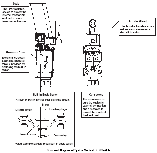
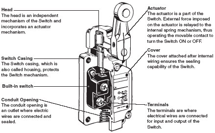
The shapes of Limit Switches are broadly classified into Horizontal, Vertical, and Multiple Limit Switches. The structure of a typical vertical Limit Switch is shown in the following figure as an example. Limit Switches are generally composed of five components.
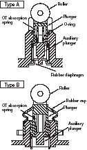
The drive mechanism of the Limit switch is an important part of the Limit Switch and is directly linked to seal performance and operating characteristics. Drive mechanisms are classified into three types, as shown in the following figure.
There are two types of plunger (types A and B in the figure) depending on the sealing method. With type A, an O-ring or a rubber diaphragm is used for sealing. The rubber seal is not externally exposed, and so resistance is provided against cutting debris from machine tools, but sand and fine shavings may become stuck on the sliding surface of the plunger. With type B, sand and fine shavings will not become stuck, and the sealing performance is superior to type A, but hot cutting debris striking the Switch may damage the rubber cap.
Whether type A or type B is required depends on the location in which the Switch is to be used. With the plunger drive, the movement of the plunger piston enables air to be compressed and taken in.
Therefore, if the plunger is left pushed in for a long time, the air in the Limit Switch will escape and the internal pressure will become equivalent to atmospheric pressure. This will cause the plunger to tend to reset slowly even if an attempt is made to quickly reset it. To prevent this problem from occurring, design the system to limit the amount of air compressed by pushing in the plunger to 20% or less of the total air pressure in the Limit Switch. To extend the service life of the Limit switch, the plunger drive includes an OT absorption mechanism that absorbs the remaining plunger movement using an OT absorption spring and stops the movement of an auxiliary plunger that pushes the Built-in switch according to the movement of the plunger.
The amount of plunger movement is increased at the end of the lever (i.e., roller) by the lever ratio, and so an absorption mechanism is generally not used.
The structure of the WL is shown as a typical example. Other drives include those in which the plunger performs the function of the reset plunger and those in which a coil spring is used for the reset force and a cam is used to move the auxiliary plunger.
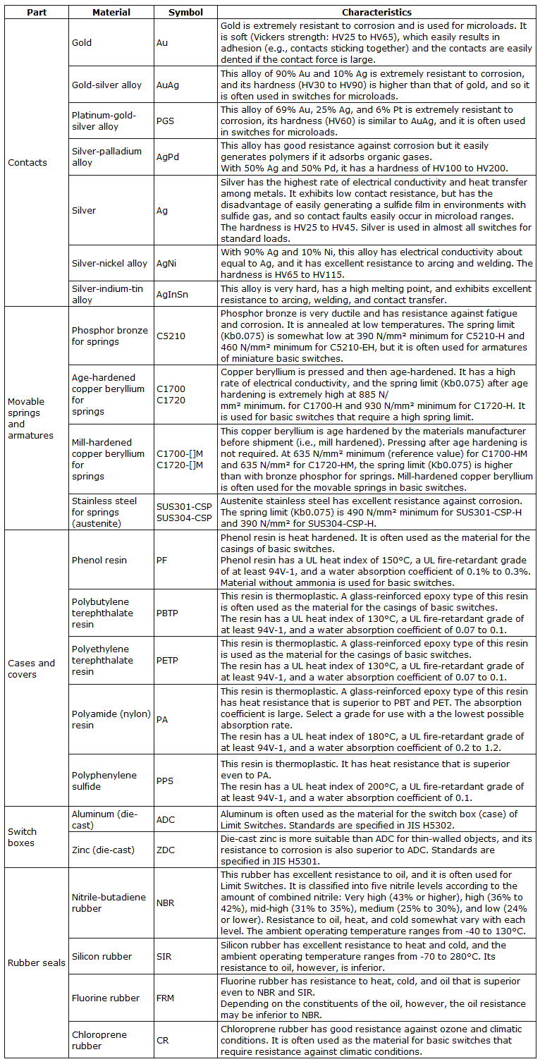
The main parts of the Switch are formed from the following materials.
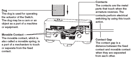
A Built-in switch enclosed in a metal or resin case to protect it from external forces, water, oil, dust, dirt, etc. Also abbreviated to merely "Switch".
Generally, the ratings of the Switch refer to values that ensures the characteristics and performance of the Switch, such as rated current and rated voltage under specific conditions.
Contacts are mechanically opened and closed for current switching.
The electrical input/output circuit configuration of contacts which depends on the application.
Terminals that are hardened by applying resin after lead wires have been connected in order to eliminate any exposed current-carrying parts and to improve sealing performance.
The mechanical durability refers to the number of available switching operations on condition that the Switch is actuated to the OT position per operation.
The electrical durability is the switching durability at the rated load (i.e., a resistive load) with overtravel set as the reference value.
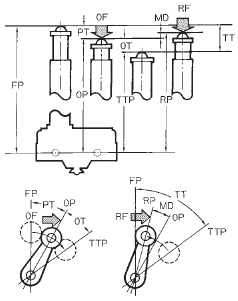
The initial position of the actuator when no external force is applied.
The position where the movable contact reverses from the free position when an external force is applied to the actuator.
The position of the actuator when it reaches the stopper.
The actuator position where the movable contacts reverse from the operating position to the free position when the external force on the actuator is reduced.
The force applied to the actuator required to operate the switch contacts.
The value to which the force on the actuator must be reduced to allow the contacts to return to the normal position.
The distance or angle through which the actuator moves from the free position to the operating position.
The distance or angle through which the actuator moves from the operating position to the total travel position.
The distance or angle from the operating position to the releasing position.
The distance or angle through which the actuator moves from the free position to the total travel position.
The following provides information on the following terms used in this catalog.
EN standards applicable to electronic machine control circuitry, the contents of which are the same as those of IEC 60947-5-1.
Switch application categories. Refer to the following examples.

Instantaneous overvoltage generated from the closed circuit, which must not exceed the Uimp value.
The minimum space distance between two charged parts.
The minimum distance on the surface of the insulator between two charged parts.
The minimum direct distance between the charged part and the nonmetal switch housing through air or any other insulator.
Rated current for the Switch to operate.
The rated switch operating voltage, which must not exceed the rated insulation voltage (Ui).
The maximum rated voltage at which the insulation voltage of the Switch is maintained. This value is used as the parameter of the dielectric strength and creepage distance of the Switch.
The normal carry current that does not increase the permissible upper-limit temperature of the Switch if it is a model with its charged part sealed. The rated permissible upper-limit temperature is 65°C if the terminals are made of brass.
The peak impulse voltage that the Switch can withstand with no insulation breakage.
The current that the Switch can withstand until the circuit breaker operates.
The device, such as a breaker or fuse, which breaks the current to protect the Switch from short-circuiting.
The environment in which the Switch is used. The pollution degree is divided into four levels as shown below. The Switch falls under pollution degree 3.

Electric Shock Preventive Levels.
