Functions Required of Motor Protective Relays
Motor Protective Relay applications can be grouped by purpose into the following categories.
Motor Protective Relays have the following functions built in to provide functions (1) and (2) above.
These functions are described in more detail below.
The motor will catch fire if it is overloaded and overcurrent is supplied for an extended period of time.
This is why overload current must be instantly detected to shut down the motor and protect it from damage.
Unfortunately, overcurrent around 500% the rated current is generally present with inductive motors anywhere from several seconds to several tens of seconds at startup as shown in Fig. 1. If the motor's overcurrent element operates at that point, the motor will shut down immediately upon startup and will not run. Therefore, Motor Protective Relays need to have an overcurrent element that detects whether current exceeding the rated value is being supplied to the motor as well as a time element that will not operate with overcurrent present only during motor startup time, but will operate if overcurrent is present beyond that time. In other words, the time element is required to prevent faulty Motor Protective Relay operation when the motor starts.
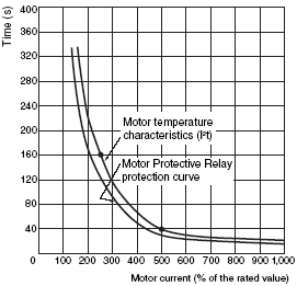
The time element is required for another very important reason. Fig. 2 shows the I²t curve for the temperature characteristics of the motor. The motor will operate normally and will not burn as long as it is operated in the area below this curve. In the example, the motor can operate normally even though overcurrent around 500% the rated current is supplied to the motor for 40 seconds. If the current is halved to 250%, then we get the following:

and the motor will operate normally for up to four times the time in the previous example, or 160 seconds. If we try 100% the rated current, then we get the following:

meaning the motor will last only 1,000 seconds according to the preceding formula. However, the formula is not applicable in this case because the motor can in fact operate continuously since 100% is the rated current. The curve then is an approximation rather than a precise representation of I²t.
This does not mean that the motor will burn up immediately with that much overcurrent supplied to it. There is some built-in time flexibility to allow the motor to withstand the overload resulting from the starting current and startup time. To allow the motor to operate within those parameters then, overcurrent should not cause the Motor Protective Relay to operate immediately. The better choice would be to use activation time characteristics, or the so-called inverse time-delay characteristics, selected to operate the Motor Protective Relay quickly for large currents and take longer to operate for low currents to ensure motor operation in the area below the curve shown in Fig.2. This is precisely why the time element is added to the overload element. It prevents unnecessary work stoppages that would occur should the Motor Protective Relay operate immediately when overcurrent is present.
This is not true for every application, however. In cases where the load is fixed and current exceeding the rated value clearly is an abnormal condition for the load, then failure to shut down the motor immediately when overcurrent is supplied will damage the load and the damage may spread through the system. The fastest possible overload element activation time is always preferable for load protection applications. Even here, a significant motor starting current will be supplied even in these applications, so an overload element is needed that will not operate for a specified period of time at startup and can operate instantly in subsequent operation. These are generally referred to as instantaneous elements.
The preceding section describes why overload elements require both a current-detecting element and a time element, but how do you select these current and time values?
The JEM 1357 standard (Inductive and Static Protective Relays for Three-phase Inductive Motors) stipulates that the must operate value should fall between 105% and 125% of the current SV and the majority of Motor Protective Relay manufacturers conform to this standard. This value is sufficient for any motors unless otherwise specified.
JEM 1357 also stipulates a maximum time value of 40 seconds for overcurrent that is 600% of the current SV and 4 minutes for overcurrent that is 200% of the current SV.
JIS B 8324 (Submersible Motor-Pumps for Deep Well) stipulates that elements must operate within 5 seconds for current five times the total load current to protect motors. There are various types of general Motor Protective Relays with activation times ranging from several seconds to several tens of seconds for overcurrents of 500% the rated value.
Fig.1 Motor Startup Current
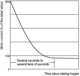
Fig. 2 Motor Temperature Characteristics and Protection Curve
Summary of overload elements
1. The current element of the overload elements will not operate at the rated current and is generally set to operate at 125% of the rated value. Set the time to several seconds or several tens of seconds with an overcurrent of 500% of the rated value and set it longer than the motor's startup time. With inverse time-delay characteristics, the time characteristics are normally set for quick activation with high currents and slow activation with low currents.
2. Some time elements operate with the same time characteristics at startup and in subsequent operation and other time elements have a time delay only at startup and operate instantly to protect loads connected to the motor in subsequent operation. The latter are generally referred to as instantaneous elements.
The operation resulting from an open motor power line or a motor that was originally supposed to operate with three-phase voltage, but is currently operating with single-phase voltage because of loose connections, faulty control switch connection, or an open wire in the motor is called open-phase operation.
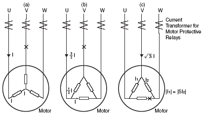
If the motor starts up under open-phase conditions, startup current will be supplied indefinitely because a stopped inductive motor will not start with a single-phase voltage. Therefore the overload element described earlier can be used to detect this condition and prevent the motor from burning up. Should an open-phase condition occur during normal operation and result in single-phase operation, however, the three-phase inductive motor will continue to operate as a single-phase inductive motor if the load is light enough. Refer to Fig. 3. The three possible conditions are a power-supply open phase in a star-connected motor, a power-supply open phase in a delta-connected motor, and an internal delta open phase. Let's see whether we can prevent the motor from burning up here simply by inserting an overload element in the power supply line.
1. Open-phase in a Star-connected Motor
As shown in Fig. 3 (a), the power supply line current and the motor winding current are the same no matter where the line is open. This means the motor will not burn up because the overload element on the power supply line will detect overcurrent if an open-phase condition occurs. The overload element cannot detect overcurrent if it does not reach the element when the motor load is light, but the motor will not burn up here again because the current is too low and operation will continue with the lighter load.
Fig. 3 Open-phase Current Distribution
2. External Open-phase with a Delta-connected Motor
Let's see what happens with the situation shown in Fig. 3 (b). If we make I the winding current during normal operation, then the power supply line current is  . If we make In the rated current in the windings, then the rated current of the power supply line will be
 ![]() and the overload element will monitor the equivalent winding current to determine whether In < I by observing whether
and the overload element will monitor the equivalent winding current to determine whether In < I by observing whether  <
<  .
.
In the open-phase condition shown in (b), however, the power supply line current will be 3/2In when I = In. This means that 3/2 In < , or 1.5 In < 1.732 In. Depending on the overload status of the motor then, the overload element will not operate because the power line current will be below the rated current even with overcurrent in the windings and the windings may burn. Therefore a separate phase-detecting element must be installed in such cases to prevent the motor from burning.
3. Internal Open-phase with a Delta-connected Motor
Let's look at the situation in Fig. 3 (c). With I1 and I2, |I1| = |I2| just as in normal operation with a phase difference of 120°. The V-phase power supply line current then is again just as in normal operation while the U- and W-phase currents are I1 and I2, respectively. Since an overcurrent higher than that found in normal operation is supplied to the windings when viewed from the standpoint of the power supply line, the overload element will detect the overcurrent and prevent the motor from burning. The wiring here then is essentially the same as that in (1) . The description so far has been directed toward preventing the motor from burning.
Fig. 4 Vector Diagram for Open-phase Power Supply Line Current
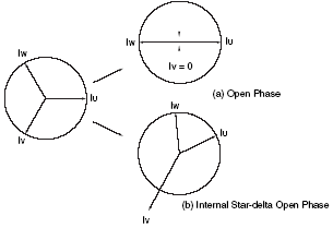
An open phase is an abnormal condition. It is not advisable to allow the motor to continue to run with an open-phase condition even with a light load. The slightest increase in the load could stop the motor from running. Short-circuiting or electrical shock accidents could also occur if someone were to touch the outer covering of a disconnected inductive line.
The fundamental principle of protection is to detect and dispose of error conditions immediately and therefore protection is not limited strictly to preventing the motor from burning. The fundamental principle is always to detect open-phase conditions as quickly as possible.
In other words, open-phase elements are generally installed in situations like those shown in Fig. 3 (a) and (c) to speed up the detection process because it takes a while for overload elements to detect open-phase conditions with light loads rather than merely preventing motors from burning.
There is one other thing to keep in mind about open-phase elements. The U-, V-, and W-phase currents in Fig. 3 (a) and (b) are balanced during normal operation, but the power supply line current of the open phase when an open-phase condition occurs will drop straight to zero and single-phase reciprocating current will be supplied to the other two phases. In this case, the vector relationship before and after the open-phase occurrence changes dramatically as shown in Fig. 4 (a).
We know intuitively that the vector in Fig. 3 (c) will change the way it did in Fig. 4 (b) and that it is not as significant as that in Fig. 4 (a). In fact, it will be harder to detect an open phase with the situation in Fig. 3 (c) than with the situation in Fig. 3 (a) and (b).
Normally the condition shown in Fig. 3 (a) and (b) is referred to as open phase and the condition shown in Fig. 3 (c) is referred to as internal star-delta open phase. The most common detectable open phases are those shown in (a) and (b), so special care must be taken when using star-delta inductive motors (the most common of which are 1.5 kW or higher).
Fig. 5 Current-type Open-phase Element Ranking
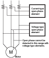
There are other methods that use motor voltages rather than current transformers to detect open phases as shown in Fig. 5. This method cannot, however, detect an open phase on the motor side because of where the connecting point for open-phase detection is located. An open phase cannot be detected on the power supply side with light load operation either because the motor terminal voltage will not drop very much. For these reasons, the current method is the better choice for detection.
Open-phase Element Summary
If the phase sequence is reversed with three-phase inductive motors, the rotating direction of the motor will be reversed. There are no applications that allow motor rotation in just any direction and even the briefest reversal may be fatal to the load. This is why we have a reverse-phase element that will instantly detect when the phase sequence of power supplied to the motor is reversed.
Fig. 6 Comparison between Voltage and Current-type Reverse-phase Elements
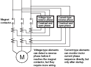
Current- and voltage-type elements can be used for reverse-phase detection as in open-phase detection. Refer to Fig. 6. If a reverse-phase element is installed prior to the magnet contactor as shown in Fig. 6, a reverse phase can be detected before the motor is started. This can prevent the motor from operating in reverse even briefly as mentioned earlier. The fastest the current-type element can operate is 0.5 s, so some reverse operation is unavoidable. This makes the voltage-type element more practical. The drawback to the voltage-type element, however, is that there is one more connection to the Motor Protective Relay, and a VT must be installed when using a high-voltage motor, for example. The advantage of the current-type element is that it can determine the phase sequence of current supplied to the motor directly, but the drawback as mentioned earlier is that it requires a little time before it can start detecting (the motor starts before the reverse current is detected).
In both cases, the phase sequence is only detected in reverse-phase detection at the connection point (power line position for voltage detection and CT position for current detection). This means that special attention must be paid to this point during installation.
It is extremely rare that the phase sequence would be reversed after the motor was installed, and thus a reverse-phase element is often not required. There are cases, however, when installing a reverse-phase element would be best, such as in applications where connections are often changed, such as for motors with mobile power supplies, or in applications where connections are changed for maintenance.
Reverse-phase Element Summary
There are several problems that must be addressed with using a motor and Motor Protective Relay. The following section describes an open-phase voltage drop, motor current waveform distortion, capacitor installation to improve the power factor, and unbalanced motor currents.
Open-phase Voltage Drop (Power Supply Connection Precautions)
Protection will be disabled, however, if the magnet contactor power supply and Motor Protective Relay power supply are out of phase. As shown in Fig. 7, for example, both the Motor Protective Relay and magnet contactor are drawing power from the U and W phases, but if we make it so only the magnet contactor is drawing power from the U and W phases, then the magnet contactor will not reset despite an open V phase because the rated voltage will be applied to the contactor and the Motor Protective Relay cannot operate because only half the voltage is applied to it. Therefore you can operate the Motor Protective Relay with half the voltage or reset the magnet contactor with half the voltage through careful wiring. Care is required either way.
Fig. 7 Open-phase Voltage Drop and Phase-advance Capacitor Position
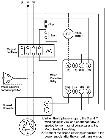
Note: An open phase will not drop the voltage to half while the motor is operating with a light load because near-normal voltage is inversely supplied from the motor side. In that case, the protection expected from magnet contactor release voltage is not achieved.
Motor Current Waveform for a Ventilation Fan
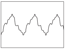
Current should be supplied to the motor with the sine wave shown in the figure above, but highly distorted current waveforms have been observed in some battered, old submersible motors that are operating perfectly fine.
Motor Protective Relays are designed for sine wave input, so distortion of the waveform will increase activation current value errors with overload elements or cause open- and reverse-phase elements to operate improperly. You could conclude from this that voltage-type fast activating reverse-phase elements are preferable over current types because there is generally less distortion in the voltage waveforms of motors. However, manufacturers have conducted countless studies on the problem of waveform distortion and there is very little difference between the two types today.
Capacitor Installation to Improve the Power Factor
Install an advance-phase capacitor parallel to the motor as shown in Fig. 7 to improve the motor's power factor. Current supplied to a motor with a light load is almost always reactive and susceptible to infusion of higher harmonics. Installing a capacitor parallel to the motor will negate the fundamental harmonic component leaving only higher harmonics. If the harmonic current is significant, then the open-phase and reverse-phase circuits designed for 50/60 Hz sine wave input tend to malfunction. This rarely occurs because the harmonic current is generally low. It is safer, however, to install the capacitor before the Motor Protective Relay as shown in Fig. 7 to lower the odds of circuit malfunction.
If the capacitor is installed after the Motor Protective Relay, the motor current appears to drop. The problem is that you have to anticipate that drop when setting the overcurrent must-operate value for the Motor Protective Relay. From that standpoint, you should apply no more than the motor current to the Motor Protective Relay.
Current Converter
A current converter consists of a current transformer that steps down motor current to a level the transistor circuits can handle, a three-phase full-wave rectifier diode that rectifies the secondary current from the current transformer, and a resistor that converts the rectified current to a DC voltage.
This current converter in particular has been designed for use with a wide range of motor currents. The taps in the current converter can be switched to vary the resistance in three levels. You could, for example, output 21 V from the current converter by connecting a 600-? resistor for a motor current of 80 A, a 1,200-? resistor for a motor current of 40 A, or a 2,400-? resistor for a motor current of 20 A. The output from the current collector is always 21 V, so the Motor Protective Relay can be set to operate at 20 A, 40 A, or 80 A simply by switching the taps using 21 V for activation.
(Note: The voltages and resistances are example values.)
The current converter can also be operated at 10 A by selecting the 20-A activation tap and winding the motor power line twice around the converter so 10 A looks like 20 A. Similarly, it can be operated at 5 A by winding the power line around the current converter four times.
Fig. 8 Internal Block Diagram of the SE-series Static Motor Protective Relay (Inverse Time-delay Type)
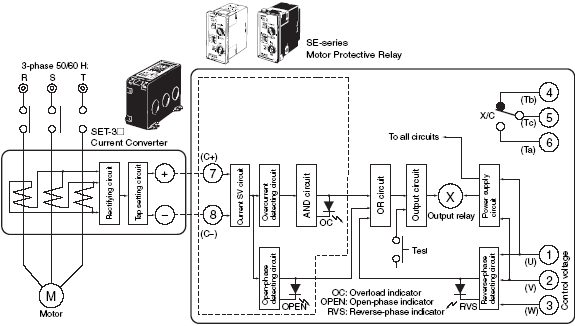
Note: 1. These figures are plug-in terminal numbers. The parentheses indicate panel-mounted terminal symbols. 2. Terminal 3 (W) does not have to be wired if the reverse element is OFF.
The current converter output is input to the Motor Protective Relay via lines to terminal 7 (C+) and terminal 8 (C-). (The figures here are plug-in terminal numbers and the parentheses indicate terminal numbers for embedded models.) There the current is first split by the current scale SV circuit and then input to the overcurrent detection circuit. The current scale SV circuit is a simple potentiometer-type voltage splitter that can convert current must operate values by varying the split rate. If the 20-A tap is selected here, then the must operate value can be set between 8 and 20 A by turning the potentiometer knob. When overcurrent occurs, the overcurrent detection circuit will detect it and drive the next time SV circuit. This time SV circuit has the inverse time-delay characteristics described earlier and its time characteristics are shown in Fig. 9.
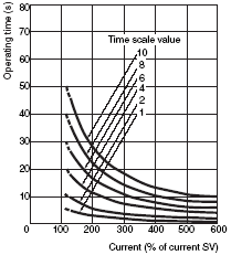
Fig. 9 Overload Activation Time Characteristics (Reference values)
Time Changeover Switch: × 1
Time Changeover Switch: × 4
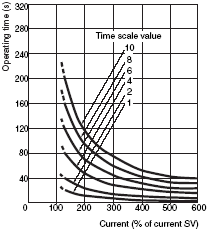
The time SV circuit also contains a potentiometer. The operating time can be varied between 2 and 10 s by turning the potentiometer know when current 600% of the current SV is supplied. It also has a multiplier switch that can increase the operating time by a factor of 4, that is between 8 and 40 seconds. One feature of the time SV circuit then is the wide time selection range from 2 to 40 s.
When overcurrent flow continues beyond the SV time settings, the output relay (X) is energized from the output circuit through the OR circuit, the contact switches from X to c, and the alarm, breaking, or other action associated with the contact is operated. With an instantaneous Motor Protective Relay, the motor is considered to have started when motor current exceeds the rating by at least 30% and the start time circuit will begin operating. There is no output for a prescribed period of time, however, regardless of the size of the input current. The overcurrent detection circuit operates immediately and generates an output, but the motor will not operate without the AND output. After the startup time has elapsed, motor current ranging from the rating to 50% of the rating will be supplied and the startup time circuit output will continue without interruption.
The overcurrent detection circuit will operate as soon as overcurrent is detected and the (X) relay will operate less than 0.5 s later.
Fig. 10 Internal block diagram of the SE Static Motor Protection Relay (instantaneous type)
The box (box symbol) on inverse time-delay models indicate the following:
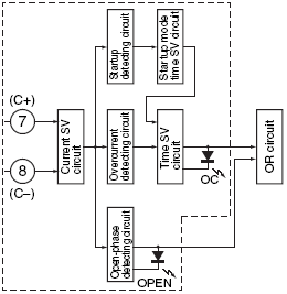
(Manual Reset Type)
SE: The (X) relay is a mechanically self-holding relay that operates until it is manually reset even if the power goes out.x
K2CM: The (X) relay remains locked even if the power goes out because it uses a keep relay system. A power supply is required to reset the relay.
(Automatic Reset Type)
The relay will reset automatically if the power drops below the set value. (An open phase will reduce the operation power supply output if the relay is used in conjunction with an open-phase element. Therefore, use another power supply other than the motor power supply for the U and V phases. Reverse-phase elements cannot be used for this reason.)
Fig. 11 Current Converter Output Waveform

Fig. 11 (a) shows the rectified output waveform during normal operation, (b) shows the waveform with an open phase, and (c) shows the waveform with an open phase in a star-delta inductive motor. From this we know that the DC component is large, the AC component is small, and the frequency component is high from at least the 6th harmonic during normal operation. We also know that the DC component is small, the AC component is large, and the 2nd AC component harmonic is the largest with an open phase. We can conclude then that an open phase can be detected with a circuit structured to respond to the second harmonic/DC component ratio or the AC component/DC component ratio.
Fig. 12 Structure of an Open-phase Detection Circuit

The static Motor Protective Relay conforms to this principle, so an open-phase has occurred when the ratio of the DC component extracted by one filter and the second harmonic component extracted by another filter from among the current converter outputs (more precisely the split voltages) has been exceeded. As shown in Fig. 13, the operating time of the relay with an open phase is approximately 1.5 seconds regardless of the current.
Fig. 13 Open-phase Operating Characteristics
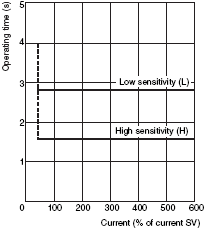
It has been found, however, that the 2nd harmonic component/DC component approximates an unbalanced rate function. This means that the Motor Protective Relay is designed more for unbalanced detection than for open-phase detection and it is set to operate when the unbalanced factor reaches approximately 35%. Fig. 14 shows how the unbalanced factor varies with the current value.
Fig. 14 Unbalanced Operation Characteristics
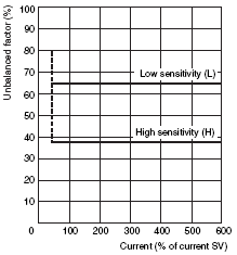
The current plotted on the horizontal axis represent the largest of the three phases. When the open-phase detection circuit provides an output, the (X) relay will operate via the OR circuit shown in Fig. 8.
Fig. 15 shows the schematic and Fig. 16 shows vector diagrams for a reverse-phase detection circuit. Here, the 1.5 Vuv between d and e in normal operation drop to 0 V with a reverse phase and basic reverse phase detection is achieved when 0 V is applied to the transistor. The (X) relay is operated by the output from the reverse-phase detection circuit via the OR circuit. The U and V phases supply power to the Motor Protective Relay, so you might have felt compelled to disconnect terminal 3 (W) because you did not need a reverse-phase element. This could have the opposite effect, because the Vuv can split between RP1 and CC1 and split voltage applied to the transistor may cause it to operate. It may not operate if the voltage input is low enough, but you can never be sure. You may have to switch to a circuit without a reverse-phase element in this case. This same Motor Protective Relay can be used at 50 or 60 Hz and therefore Vde never really drops all the way to zero even in normal operation. The difference in Vde between normal and reverse-phase operation is significant enough, however, to ensure stable operation.
Fig. 15 Structure of a Reverse-phase Detection Circuit
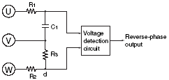
Fig. 16 Vector Diagrams for a Reverse-phase Detection Circuit
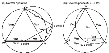
Fig. 17 (a) and (b) are examples of external connections. Terminal 3(W) does not have to be connected if a reverse-phase element is not used.
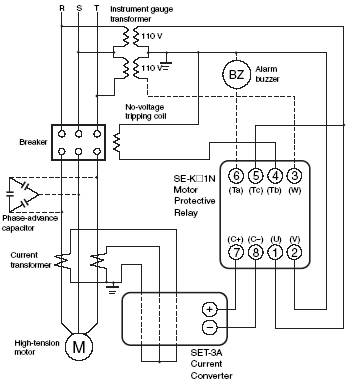
Fig. 17 External Connections for a Star-delta Startup Motor
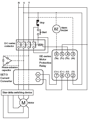
Fig. 17 (b) External connections for no-voltage tripping with high-tension inductive motors
The unbalance rate for motor current normally does not exceed several percentage points, but an unbalance rate of 10% to 20% or more has been observed in motors that have been in use for many years and motors that are supplied power through V-wired transformers.
Refer to the simple unbalance rate calculation method in the reference information on the following page. Use this method for measurement. Delta internal phase detection may not be possible if the unbalance rate exceeds 20%.
According to the law of symmetrical coordinates, the unbalance rate is defined as:

Where ![]() ,
, ![]() , and
, and ![]() are the current of the three phases and the vector operator is as follows:
are the current of the three phases and the vector operator is as follows:
This gives us a scale for expressing three-phase current and the extent of voltage unbalance. These are difficult calculations, however, and the following calculation table is a simpler way to work out the unbalance rate.
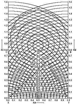
Fig. 18 is a graph for determining the unbalance rate if you know the absolute values for the three phase inputs.
If we have a three-phase AC input, for example, with a phase A current, IA, of 50 A, a phase B current, IB, of 35 A, and a phase C current, IC, of 45 A, then we can use current IA as a base and divide the other phase currents by IA to find the unbalance rate, as follows:
Check to see if arc B starting from the point KB = 0.7 on the vertical axis on the right side intersects at point P1 with arc C starting from the point KC = 0.9 on the vertical axis on the left side. The point P1 is located on the circle representing an unbalanced rate of 20%. In this case, then, we determined that the unbalanced rate will be 20%.
Similarly, KA = 1.0, KB = 1.3, and KC = 1.0 when IA = 50 A, IB = 65 A, and IC = 50 A. The intersecting point for these arcs is P2, and P2 is close enough to the circle representing an unbalanced rate of 20% that we can conclude the unbalanced rate here too is 20%. The intersecting points for arcs emanating from any KC and KB
combination falls on the 20% unbalanced rate circle and all have an unbalanced rate of 20%. We know from this that there are an infinite number of combinations with the same unbalance rate.
Similarly, D1 through D8 represent all combinations with an unbalance rate of 25%.
If we consider star-delta P1XY then XY = IA, P1X = IC, and P1Y= IB. In other words, star-delta P1XY yields a vector diagram for IA, IB, and IC.
Fig. 18 Calculating Table for the Unbalanced Rate of Three-phase Current and Voltage
There are all kinds of motor circuit failures and protective devices designed for specific purposes must be used to protect against such failures. The following describes various motor accident details and protective measures.
There are a variety of protective devices, including 3E relays, thermal relays, and motor circuit breakers, and they are summarized below. All the protective devices for motors have specific functions.
Unfortunately none of these functions can reach their full potential unless they are used properly. This is why you must select the proper device for the type of protection you require.
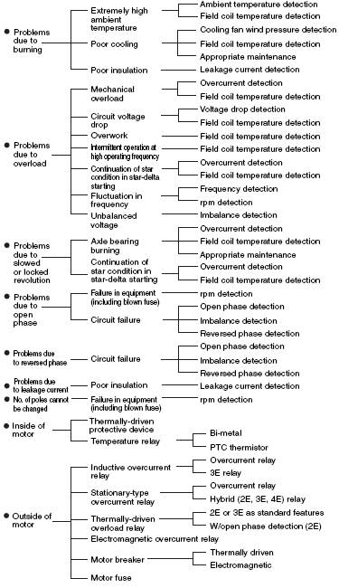
Variation in the types of inductive motors available today leads to many types of failures.
The following table lists appropriate protective devices for these motors.
Purpose of Protection and Applicable Protective Relays for Inductive Motors
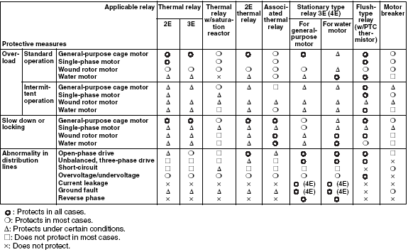
As discussed above, there are various motor protective equipment and devices available. The 3E Relay is provided with three features to protect motors: protection from overload, open phase, and reverse phase. These three features of the 3E Relay are discussed next.
Overload Protection
The overload protection feature of the 3E Relay protects the motor from overload when it operates normally. With this feature alone, the motor can be protected most of the time. To ensure effective protection, it is necessary to set correctly the "must operate voltage" and operate time of the 3E Relay.
The PC characteristics curve of the 3E Relay, (which is used as a yardstick when designing a motor protection system) can be drawn in the following procedure.
Protective Coordination of Motors
When designing a motor system, adequate considerations must be given to whether the motors and their circuits can be effectively coordinated with other equipment and devices. It is important that each motor operates in protective coordination (PC) with the devices listed in the following table.
| Electromagnetic switch | |
| Molded case circuit breaker (MCCB) | |
| Branch circuit wiring | |
| Thermal relay or 3E relay |
Creating a PC Characteristic Curve
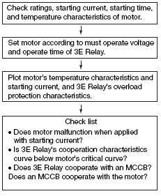
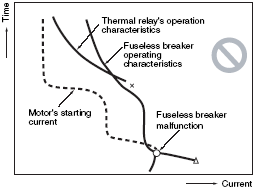
As examples, correct and incorrect PC characteristic curves are shown below.
CORRECT
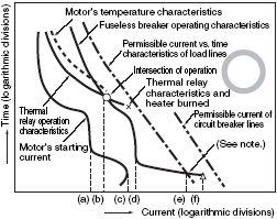
Note: The current value at the end of the load line must be lower than this value.
INCORRECT
Open-phase Protection
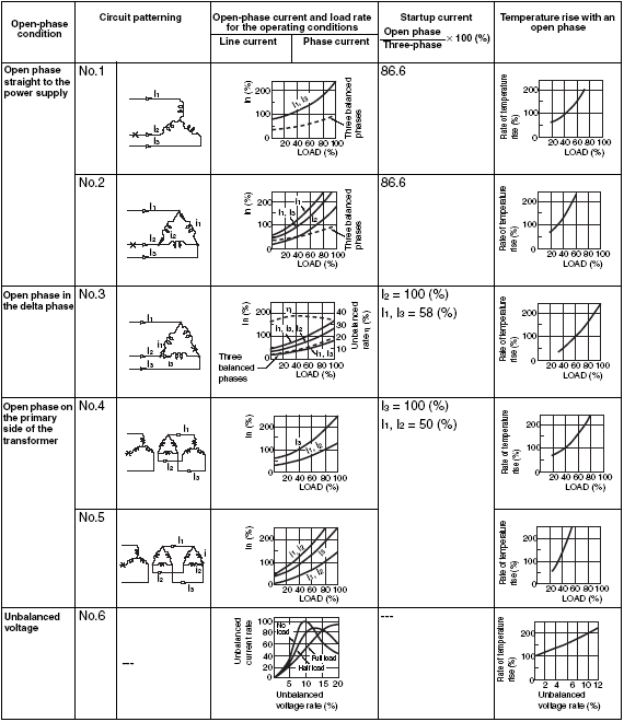
An open-phase condition refers to single-phase motor operation that results from a broken motor power line or loose power line connections, faulty switch contact, or a broken wire in a motor. When it occurs, the phase current increases markedly compared to the increase in motor line current, the winding temperature exceeds the permissible limit, and the motor will burn up in some cases. Open-phase protection is needed here rather than overload protection. The figure shows open-phase accidents and current fluctuations. The point of the figure is to show that the increase in phase current is relatively higher than the increase in line current in cases 2, 3, and 5 in the figure and that line current overload detection cannot always detect failures.
There is no need to set the activation values on the user end because open-phase detection sensitivity is fixed. Examples are provided here, however, because these failures are so difficult.
Reverse-phase Protection
The motor rotating direction will be reversed if the phase sequence is reversed. Reverse-phase elements will detect the phase sequence of the power supply and will lock up the motor during startup if the phases are reversed. Phase sequence detection is no longer needed once the elements are properly installed. Although one side effect of the elements is motor protection, the main purpose is to protect the load.
Open-phase Accidents and Current Fluctuation
