Rotary Encoders measure the number of rotations, the rotational angle, and the rotational position. Linear Encoders are also available to measure linear movement.
Rotary Encoders are sensors that detect position and speed by converting rotational mechanical displacements into electrical signals and processing those signals. Sensors that detect mechanical displacement for straight lines are referred to as Linear Encoders.
Linking to the shaft using a coupling enables direct detection of rotational displacement.
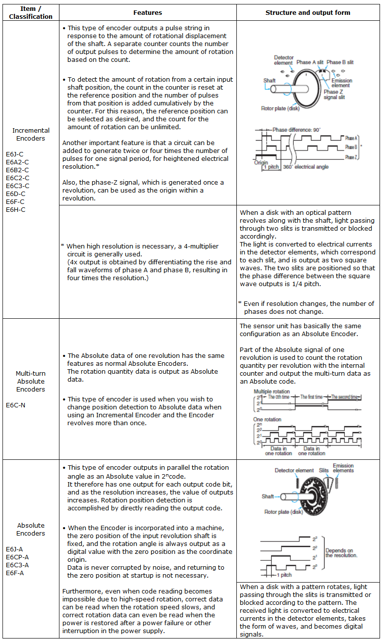
With an Absolute Encoder, the rotational angle is output in parallel as an Absolute value.
The rotation direction is determined by the output timing of phases A and B with an Incremental Encoder, and by the code increase or decrease with an Absolute Encoder.
Select the Sensor to match the requirements for precision, cost, and connected circuits.

Select a type that is suitable in terms of the cost vs. capacity, returning (or not) to the origin at startup, the maximum speed, and noise tolerance.
Select the optimal model in view of required precision and cost of machine equipment. We recommend selecting a resolution of from 1/2 to 1/4 of the precision of the machine with which the Encoder will be used.
Also take into consideration the type of shaft that is required (hollow shaft or regular shaft) in relation to mounting space.
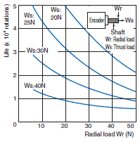
When selecting, take into consideration how the mounting method affects the load on the shaft and mechanical life.
Base your selection on the maximum mechanical speed during use.
Base your selection on the maximum shaft speed when the device in which the Encoder is used is in operation.
Maximum response frequency = (Revolutions/60) × Resolution.
There are deviations in the actual signal periods, so the specifications of the selected model should provide a certain amount of leeway with respect to the above calculated value.
Select the model based on how much dust, water, and oil there is in the application environment.
Dust only: IP50
Water or oil also present: IP52(f), IP64(f) (water-resistant, oil-resistant)
Oil present: Oil-proof construction
How much torque does the drive have?
Select the circuit type based on the device to be connected, the frequency of the signal, transmission distance,
and noise environment.
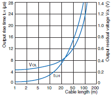
For long distance transmission, a line-driver output is recommended.


Measurement Example:
Power supply voltage: 5 VDC
Load resistance: 1 kO (Output residual voltage is measured at a 35 mA load current.)
Cable: Special Cable