Safety switches come in the form of safety door switches and safety limit switches.
Door monitoring and interlocking switches are one of the most important types of protective devices to prevent dangerous situations by taking power away from the machine.
When it is decided to protect the machine with protective fences, we must be sure that the only way inside the dangerous area is through the guard. If the guard is opened, a mechanically actuated position detector stops the machine. Every guard in the fence must have mechanically actuated position detectors to ensure the safety of personnel. A basic requirement is that it the door is opened, the machine must stop before anyone can reach the hazardous moving parts of the machine.
The most import selection criteria of an interlocking device are:
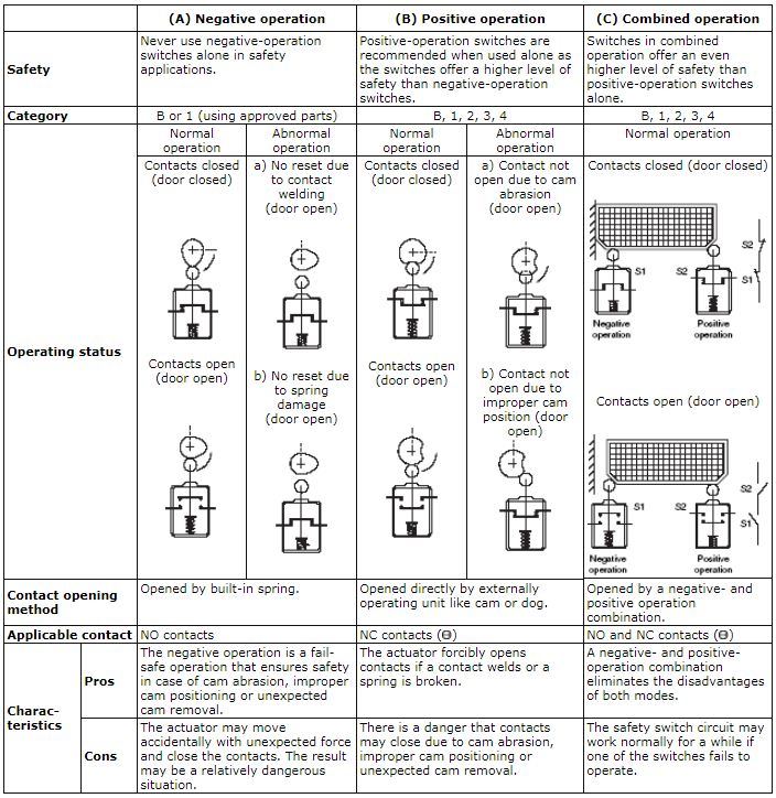
The position switch shall be actuated in the positive mode. The break contact of the position switch shall be of the “positive opening operation” type (IEC60947-5-1).
The security of an interlock switch is dependent on its ability to withstand attempts to “cheat” or defeat the mechanism. An interlock switch should be designed so that is cannot be defeated in a simple manner. This means that the intended operation will be achieved manually or with a readily available object.
Readily available objects may be:
ISO14119 “interlocking devices associated with guards” provides guidance of interlocking devices and is intended to be used together with EN60947-5-1 for electromechanical switches.
Door monitoring must ensure that the safety door protects the hazardous area as defined in the risk assessment (ISO14121). The sensors and the signal processing must comply with all required norms and directives.
An interlocking device with guard locking shall be used when the stopping time is greater than the access time taken by a person to reach the danger zone.
The device is intended to lock a guard in the closed position and linked to a control system so that:
For applications requiring frequent access, the interlocking device shall be chosen to provide the least possible hindrance to the operation of the guard.
In that case also requirements of intended use, conditions of use, risk assessment and stopping time and access time must be taken into account.
There are three types of mechanical actuation. These are:
When one single detector is used it shall be actuated in the positive mode since, among other characteristics, this mode of actuation prevents the detector from being defeated in a simple manner.
A higher level protection against defeat can be achieved, e.g., by enclosing the cam and detector in the same housing.
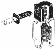
The operation key operated switch is designed to prevent easy cheating of the switch. A dedicated operation key is needed every time. These switches can be used on sliding, hinged and lift-off guards. Mainly they are used in interlocking switches.
A disadvantage in these switches is that can be defeated by using an operation key which is not attached to the guard.
Preventing this kind of defeat is possible and it can be achieved by:
• Physical obstruction or shielding preventing introduction of spare actuators
• Permanent assembly (by welding, riveting, “one way” screw) of the operating key with the guard to render dismantling more difficult.
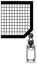
In hinged door switches it is very difficult to defeat the switch. That is a very good feature of hinged door switches. Another feature is easy use in small size guards, where key operated switches cannot be used due to operation key radius. Care must be taken for large wide guard doors because the opening angle results in a bigger movement of the door. That can result in a significant gap in the opening edge on very wide guard doors.
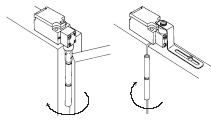
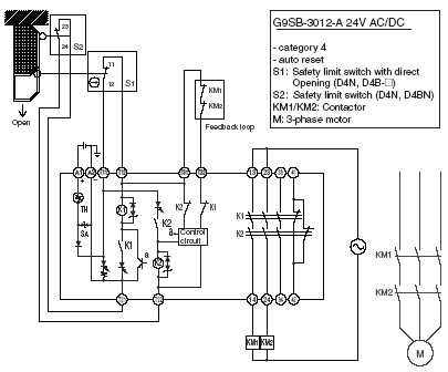
Below you will find some door monitoring application examples.
As shown in the following illustration, the safety limit switch has a positive opening mechanism that consists of inelastic, uneven parts engaged with one another so that the actuator will not be deformed or displaced by a strong force which may be applied on the actuator when a contact is welded.
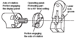
Note: The lever is secured with uneven parts so that the lever will not fail if a strong force is applied to it. The lever cannot be attached backwards.
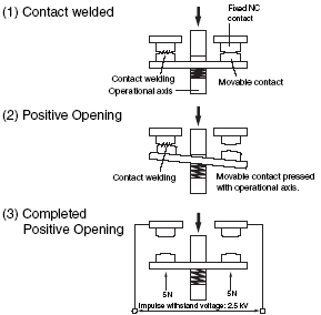
The contacts must withstand the impulse voltage specified by IEC60947-5-1 when the contacts have been forcibly opened with the positive operating force (POF) and positive overtravel (POT) exceeding the contact welding force, which is equivalent to 10 N.
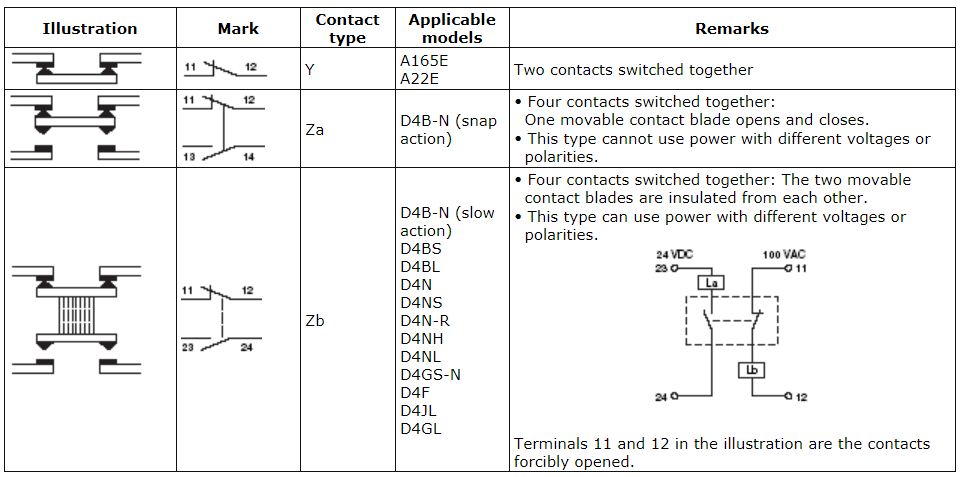
EN 60617 applies to diagram marks to be used when designing electrical circuits. EN 60617 is harmonized with IEC 60617 and JIC C 0617. These diagram mark standards must be followed in the product design.
The following figure shows contact marks used in the user’s guide as cited from EN 60617.
