(1) Safety Relay Units
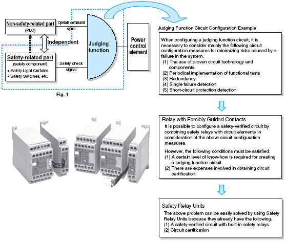
A typical configuration for the operation control of machinery and equipment is shown in Fig. 1.
Non-safety-related Parts
The role of non-safety-related parts is to start and continue the operation of devices upon receiving an operate command signal from an automatic control system.
Safety-related Parts
The role of safety-related parts is to enable operation only when the safety of the machinery and equipment is confirmed.
Judging Function
The judging function sends an operate signal to a power control element only when it has judged that both the above-mentioned operate command
signal, which is sent from a non-safety-related part, and the safety check signal, which confirms the safety of the machinery, allow operation.
Judging Function Elements
The judging function cannot be created by simply combining multiple elements.
Its circuit must incorporate elements that will minimize risks caused by a failure in machinery or equipment. These circuit configuration elements typically include items 1 to 5 shown below.
Necessity of Safety Relay Units
It is possible to configure a safety-verified circuit by incorporating safety relays with forcibly guided contacts. However, this requires a certain level of
technology to configure the circuit and some expense for its certification. As a result, it has become general practice to use standard units that specialized
manufacturers have developed by incorporating safety relays. These are provided as a series of Safety Relay Units with proven functional safety.
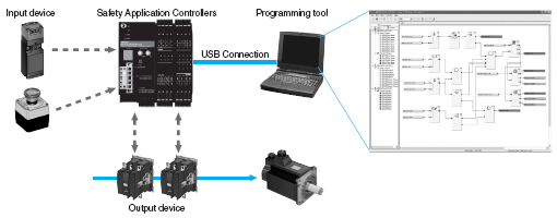
(2) Safety Application Controllers
Safety Relay Units are suited to simple relay sequence configurations for single input/single output applications. Advanced units with electronic or programmable control have been developed to handle complicated applications (with multiple inputs and outputs) that are difficult for simple relay sequences. Even in these advanced units, the following technologies ensure sufficient safety.
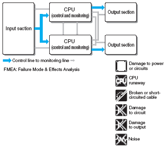
Dual CPUs
We pursued safety to the limit to deliver safety and reliability backed by the highest level of safety design and FMEA. Two CPU Units perform mutual checking and diagnostic monitoring of each I/O section, and the safety of operations is further verified by FMEA and process-controlled design and production.
 Effective Functions
1. Logic Connections
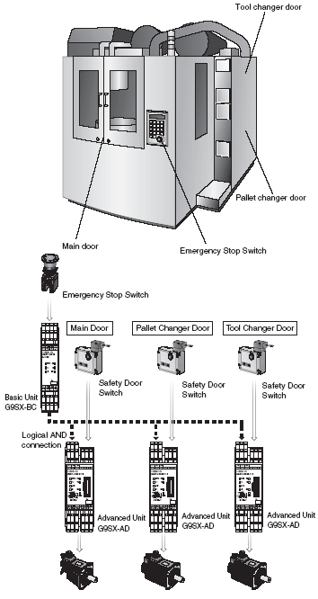
For example, an AND condition is required for both partially stopping each module of a device and stopping the entire device. By making this AND logic into a function, it can be used in combinations to enable flexible response to even complicated applications.
1. When the Emergency Stop Switch is pressed, the entire machine will stop.
2. When a door is open, the corresponding part will not activate.

(2) Programmability
By creating safety programs, the designer can more flexibly handle complex applications. There are, however, four requirements for safety in programming safety circuits.
Preventing User Programming Errors
Safety functions (such as emergency stop buttons and two-hand operating buttons) are provided as verified function blocks to ensure safety at the function block level.
(The safety of the combination of function blocks must be verified to ensure final safety.)
Preventing Unexpected Operation from Incorrect Wiring
External wiring faults are detected, including incorrect wiring, ground faults, short circuits, and disconnection. Internal circuit faults are also detected.
Preventing Unintentional Settings
Checks are performed to ensure that the parameters input by the user are correctly transferred to and set in the devices before automatically enabling starting.
Preventing System Access Except by Administrators
Passwords are set for devices to allow only administrators to change parameters, operating modes, or others aspects of operation.
(3) Networking
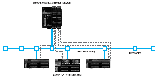
Creating networks for safety circuits enables applications that require distributing safety devices, as well as expansion of I/O capacity. The following four measures are taken in implementing safety circuit networks.
Cross-checking Communications Data (System Redundancy)
Redundancy is implemented for safety data by sending inverted data together with safety data to improve safety.
Special Check Code for Safety Data (Safety-CRC)
Check codes called Safety-CRC are attached to both the safety data and inverted data to ensure that any message corruption is detected.
IDs for Transmitters and Receivers
Safety devices have unique ID codes, which can be used by the devices to prevent incorrect data communications.
Data Time Management
Safety devices attach time stamps to the data they send. These are managed by the devices to ensure that communications are handled in a suitable timeframe and a suitable order to monitor for reversed or late communications data.
