These Controllers receive sensor signals and control heaters or other devices to maintain a preset temperature. They can also be used for humidity, pressure, and flowrate control. OMRON also provides temperature and humidity sensors.
The following example describes the basic configuration for temperature control.
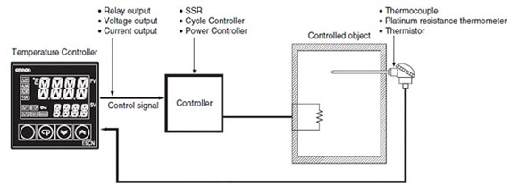
An Temperature Controller receives electrical signals input from the Temperature Sensor, compares the electrical signal input to the set point, and outputs adjustment signals to the Controller.
A Controller is used to heat or cool furnaces and tanks using devices such as a solenoid that cuts off electric current to a heater or a fuel valve that shuts off the fuel supply.
The Temperature Sensor consists of an element protected by a pipe. Locate the element, which converts temperatures into electrical signals, in places where temperature control is required.
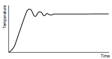
The set point is input to operate the Temperature Controller. The time required for stable temperature control varies with the controlled object. Attempting to shorten the response time will usually result in overshooting or hunting the temperature. The response time must not be shortened to reduce overshooting or hunting the temperature. There are applications that require prompt, stable control in the waveform shown in (1) despite overshooting. There are other applications that require the suppression of overshooting in the waveform shown in (3) despite the long time required to stabilize the temperature. In other words, the type of temperature control varies with the application and purpose. The waveform shown in (2) is usually considered to be a proper one for standard applications.
1. The temperature stabilizes after overshooting several times.
2. Proper response
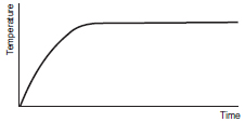
3. The response is slow in reaching the set point.
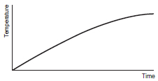
Before selecting a Temperature Controller or Temperature Sensor, it is necessary to understand the thermal characteristics of the controlled object for proper temperature control.
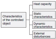
Heat capacity, which indicates the ease of heating, varies with the capacity of the furnace.
Static characteristics, which indicate heating capability, vary with the capacity of the heater.
Dynamic characteristics, which indicate the startup characteristics (i.e. excessive response) of heating, vary with heater and furnace capacity that can affect each other in a complex way.
External disturbances cause temperature changes. For example, the opening or closing of a door on a constant temperature tank can cause external disturbances that generate temperature changes.
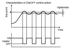
As shown in the graph below, if the process value is lower than the set point, the output will be turned ON and power will be supplied to the heater. If the process value is higher than the set point, the output will be turned OFF and power to the heater will be shut off. This control method, in which the output is turned ON and OFF based on the set point in order to keep the temperature constant, is called ON/OFF control action. With this action, the temperature is controlled using two values (i.e., 0% and 100% of the set point). Therefore, the operation is also called two-position control action.
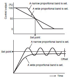
P action (or proportional control action) is used to obtain an output in proportion to the input. The Temperature Controller in P action has a proportional band with the set point in the proportional band. The control output varies in proportion to deviation in the proportional band. In normal operation, a 100% control output will be ON if the process value is lower than the proportional band. The control output will be decreased gradually in proportion to the deviation if the process value is within the proportional band, and a 50% control output will be ON if the set point coincides with the process value. (i.e., there is no deviation). This means P action ensures smoother control with minimal hunting compared with the ON/OFF control action.
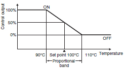
Example:
If a Temperature Controller with a temperature range of 0 °C to 400 °C has a 5% proportional band, the width of the proportional band will be converted into a temperature range of 20 °C. In this case, a full output is kept turned ON until the process value reaches 90 °C, and the output is OFF periodically when the process value exceeds 90 °C, provided the set point is 100 °C. When the process value is 100 °C, there will be no difference in time between the ON period and the OFF period (i.e. the output is turned ON and OFF 50% of the time.)
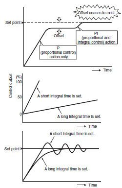
I action (integral control action) is used to obtain an output in proportion to the time integral value of the input.
P action causes an offset. Therefore if proportional control action and integral control action are used in combination, the offset will be reduced over time until the control temperature eventually will coincide with the set point and the offset will cease to exist.
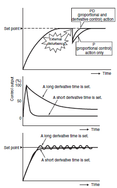
D action (derivative control action) is used to obtain an output in proportion to the time derivative value of the input.
Proportional control action corrects the control results as does integral control action. Therefore, proportional control action and integral control action respond slowly to temperature change. This is why derivative control is required. Derivative control action corrects control results by adding the control output in proportion to the slope of temperature change. A large control output is applied to radical external disturbances to get the temperature quickly back under control.
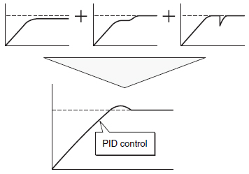
PID control is a combination of proportional, integral, and derivative control actions. The temperature is controlled smoothly here by proportional control action without hunting, automatic offset adjustment is made by integral control action, and quick response to an external disturbance is made possible by derivative control action.
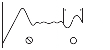
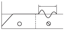
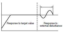
Conventional PID control uses a single control block to control the responses of the Temperature Controller to a target value and to external disturbances. Therefore, the response to the target value will oscillate due to overshooting if importance is placed on responding to external disturbances with the P and I parameters set to small values and the D parameter set to a large value in the control block. On the other hand, the Temperature Controller will not be able to respond to external disturbances quickly if importance is placed on responding to the target value (i.e., the P and I parameters are set to large values). This makes it impossible to satisfy both the types of response in this case.
Two PID control eliminates this drawback while maintaining the strengths of PID control. This makes it possible to improve both types of responses.
(1) Response to the target value will be slow if response to the external disturbance is improved.
(2) Response to the external disturbance will be slow if response to the target value is improved.
(3) Controls both the target value and the external disturbance response.
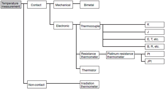
There are two categories of temperature measurement, as described below.
If the fixed winding is locked in position completely in phase with fixed winding S1-S3 (energized by sin ? voltage) for example, then sin ? voltage will be induced in R1-R2. When the rotating winding starts rotating, sin (? - a) voltage will be induced in R1-R2 because of the cos ? voltage of the S2-S4 winding that is 90° out of phase with the S1-S3 winding. (See the figure below.)
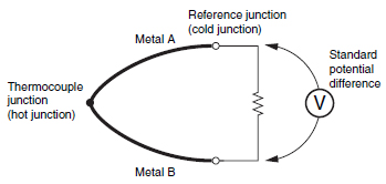
A thermocouple uses the thermoelectric force (i.e., the Seebeck effect) that is generated between different types of metal to measure temperature.
This type of combined metal wires is called a thermocouple.
The size of the potential difference is determined by the two different materials of the metal wires and by the difference in temperature between the thermocouple junction (i.e., hot junction) and standard junction (i.e., cold junction). Any difference in temperature in between has no effect (Law of Intermediate Temperatures). There is also no effect if there are different types of metals in between as long as there is no difference in temperature (Law of Intermediate Metals).
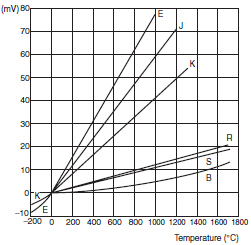
Among thermocouples, types K, E, J, and T use base metals, and types B, R, and S use noble metals.
The type of thermocouple is chosen based on the measurement temperature, environment, and accuracy. In general, however, types K, J, and R are commonly used.
These are special extension wires (cable) used when the temperature measurement point and the Temperature Controller are far apart or when a thermocouple temperature sensor with a terminal block is used.
For the thermocouple wires, use compensating lead wires in an extension cable considering the construction and resistive value. The compensating lead wires consist of materials that match the potential difference of the thermocouple to be used.
Two types are available depending on the temperature used: general purpose (-20 to 90°C) and heat-resistant (0 to 150°C). The characteristics are determined according to JIS.
This device exploits the constant relation of metal resistance to temperature.
Conditions requited for metal wire material:
1. High temperature coefficient of electrical resistance and good linearity
2. Stability
3. Ability to be used with a broad temperature range
The material which best meets these conditions is platinum. Only the platinum resistance thermometer is prescribed by JIS.
This device uses the characteristic of platinum (Pt) that causes its electrical resistance to increase in proportion to temperature.
Pt (new JIS) is prescribed at present by JIS (C1604-1997). JPt (former JIS) is often used in Japan but has been discontinued. Both types, however, are still widely used. Pt and JPt have different characteristics, so the type must conform to the input specifications of the Temperature Controller.
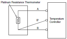
The resistance of a platinum resistance thermometer is 100 O at 0°C and the standard resistance ratio (R100/R0 value) is 1.3851 (Pt100).These values are low and so they will be greatly influenced by the compensating lead wire resistance.
Generally, wiring with a three-wire resistance thermometer is used to eliminate the influence of the compensating wire resistance.
One resistance conductor is connected to two wires and the other is connected to another wire to eliminate the influence of resistance when lead wires are extended. All of OMRON's three-wire platinum resistance thermometers are configured this way.
