Automation Systems
  Motion & Power Solutions
  Safety, Vision and IDENT
  Sensing Solutions
  Control Components
  Switching & Accessories
  Switchgear and Trolley Systems
  Process Weighing
  LED Lighting
  Omron
Omron
 Mitsubishi
 Delta
Delta
 Autonics
 Inno
Inno
 Panasonic
 Novotechnik
 Orientalmotor
 Microscan
 IPA
IPA
 Technomech
 Intech
 Honeywell
 IOT & Traceability
 Project & Panel Engg.
 Application Case Studies
 Solutions by Industry
 Solutions by Process
 Solutions by Product
 Youtube Videos
 Corporate Information
 Company Profile
 Quality Policy
 Mission Statement
 Chairman's Message
 Intech Group Companies

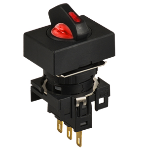
Compact Industrial SCARA
Compact Industrial Robot with light weight space saving arm. Its high speed operation is best suited for pick and place, labelling, tracking
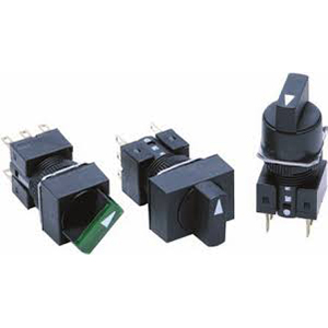

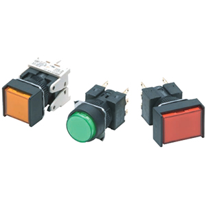
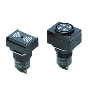
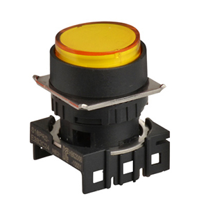
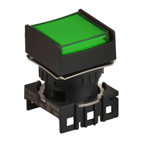
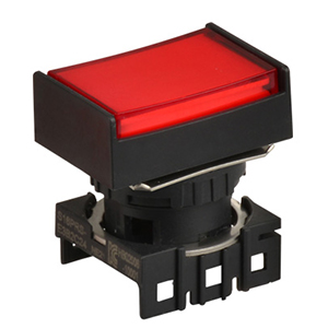
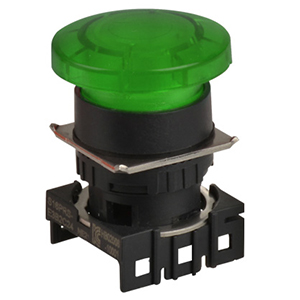
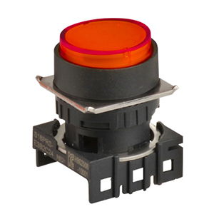
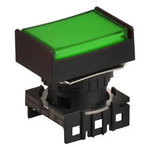
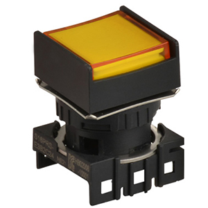
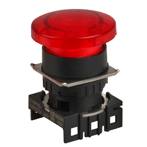
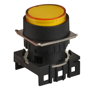
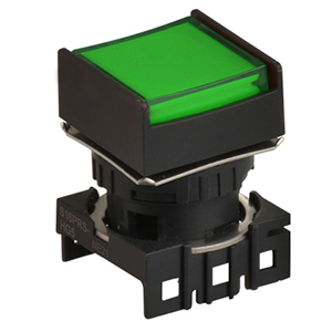
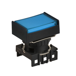
• Same separate construction as the A16-series Pushbuttons with Miniature Design of 28.5 mm
• The same contacts can be used for both standard loads and microloads.
• Oil-resistant IP65 models
• Conforms to EN60947-5-1.
5 A at 125 VAC, 3 A at 250 VAC (general use)
3 A at 30 VDC (resistive)
Note: Certification has been obtained for the Switch. For detailed information on individual products that have received certification, consult your supplier.
3 A at 250 VAC
3 A at 30 VDC
5 A at 125 VAC
3 A at 250 VAC
3 A at 30 VDC
| Rated voltage | Resistive load |
|---|---|
| 125 VAC | 5A |
| 250 VAC | 3A |
| 30 VDC | 3A |
Minimum applicable load: 1 mA at 5 VDC
Rated values are obtained from tests conducted under the following conditions.
1. Load: Resistive load
2. Mounting conditions: No vibration and no shock
3. Temperature: 20±2°C
4. Operating frequency: 20 times/min
| Name | Contact form |
|---|---|
| SPDT |

|
| Rated voltage | Rated current | Operating voltage | Internal limiting resistor |
|---|---|---|---|
| 5 VDC | 8 mA | 5 VDC ± 5% |
Red, yellow: 300 Ω Green: 160 Ω |
| 12 VAC/VDC | 12 VAC/VDC ± 5% |
Red, yellow: 1 kΩ Green: 910 Ω |
|
| 24 VAC/VDC | 24 VAC/VDC ± 5% | 2.4 kΩ |
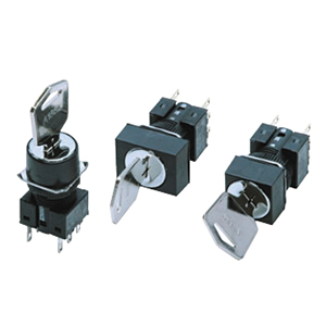
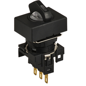
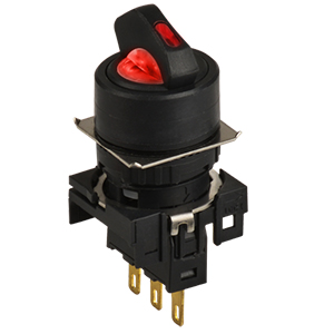
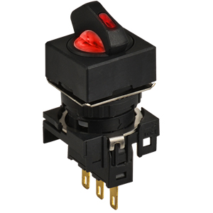
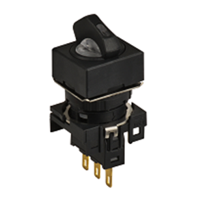
| Type | Knob-type Selector Switch | |
|---|---|---|
|
Allowable operating frequency |
Mechanical | 20 operations/minute max. |
| Electrical | 10 operations/minute max. | |
| Insulation resistance | 100 MΩ min. (at 500V DC) | |
| Contact resistance | 100 mΩ max. (initial value) | |
|
Dielectric strength |
Between terminals of same polarity |
1,000 VAC, 50/60 Hz for 1 min |
|
Between terminals of different polarity |
2,000 VAC, 50/60 Hz for 1 min | |
|
Between each terminal and ground |
2,000 VAC, 50/60 Hz for 1 min | |
| Between lamp terminals | 1,000 VAC, 50/60 Hz for 1 min * | |
|
Vibration resistance |
Malfunction | 10 to 55 Hz, 1.5-mm double amplitude (malfunction within 1 ms) |
|
Shock resistance |
Destruction | 500 m/s2 max. |
| Malfunction | 150 m/s2 max. (malfunction within 1 ms) | |
| Durability | Mechanical | 250,000 operations min. |
| Electrical | 100,000 operations min. | |
| Electric shock protection class | Class II | |
| PTI (tracking characteristic) | 175 | |
| Degree of contamination | 3 (IEC60947-5-1) | |
| Weight | Approx. 13 g (in the case of a lighted DPDT switch) | |
| Ambient operating temperature | -10°C to 55°C (with no icing or condensation) | |
| Ambient operating humidity | 35% to 85%RH | |
| Ambient storage temperature | -25°C to 65°C (with no icing or condensation) | |
* With LED not mounted.(Perform testing with the LED not mounted.)
| Item | Type | Screw-less Clamp | |||
|---|---|---|---|---|---|
| Recommended wire size | 0.5 mm2 twisted wire or 0.8 mm-dia. solid wire | ||||
| Usable wires and tensile strength | Twisted wire | 0.3 mm2 | 0.5 mm2 | 0.75 mm2 | 1.25 mm2 |
| Solid wire | 0.5 mm dia. | 0.8 mm dia. | 1.0 mm dia. | --- | |
| Tensile strength | 10 N | 20 N | 30 N | 40 N | |
| Length of exposed wire | 10 ± 1 mm | ||||
| Compliant | JIS C 2811 Terminal Blocks for Industrial Use | ||||
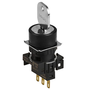
| Type | Knob-type Selector Switch | |
|---|---|---|
| Characteristics | 2 notches | 3 notches |
| Operating torque (OF) max. | 0.1 Nm | |
| Set position (SP) | 90 ± 5 ° | 45°+10, 0 |
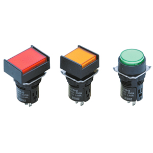
• The Dimension shows 2-switch outputs.
• The lamp terminal is not provided with non-lighted models.
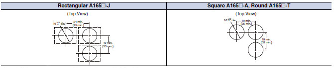
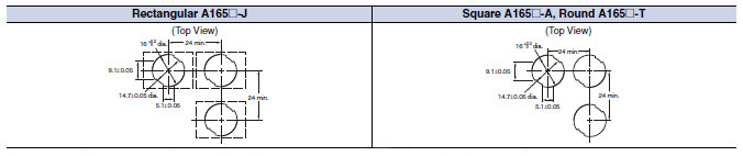
Note: See below for panel cutouts.
Note: See below for panel cutouts.
Note: See below for panel cutouts.
The lamp terminal is not also provided with nonlighted models.
Note: See below for panel cutouts.
The lamp terminal is also provided with nonlighted models.
Note: 1. Make sure the thickness of the mounting panel is 0.5 to 3.2 mm.
2. If the panel is to be finished with coating, etc., make sure that the panel meets the specified dimensions after coating.
3. Figures in parentheses are for screw-less clamp connectors.
Note: 1. Ensure that the variation in the distance between the centers of neighboring mounting holes is less than ±0.1 mm.
2. Make sure the thickness of the mounting panel is 0.5 to 3.2 mm. If, however, a Switch Guard or Dust Cover is used, the thickness of the mounting panel must be 0.5 to 2 mm.
3. If the panel is to be finished with coating, etc., make sure that the panel meets the specified dimensions after coating.