Automation Systems
  Motion & Power Solutions
  Safety, Vision and IDENT
  Sensing Solutions
  Control Components
  Switching & Accessories
  Switchgear and Trolley Systems
  Process Weighing
  LED Lighting
  Omron
Omron
 Mitsubishi
 Delta
Delta
 Autonics
 Inno
Inno
 Panasonic
 Novotechnik
 Orientalmotor
 Microscan
 IPA
IPA
 Technomech
 Intech
 Honeywell
 IOT & Traceability
 Project & Panel Engg.
 Application Case Studies
 Solutions by Industry
 Solutions by Process
 Solutions by Product
 Youtube Videos
 Corporate Information
 Company Profile
 Quality Policy
 Mission Statement
 Chairman's Message
 Intech Group Companies

Compact Industrial SCARA
Compact Industrial Robot with light weight space saving arm. Its high speed operation is best suited for pick and place, labelling, tracking

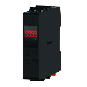
• Character height of 4.8 or 3.2 mm makes for easy-toview display.
• Installation is easy with snap-in mounting.
• The series includes a complete range of locking-type models that prevent accidental operation.
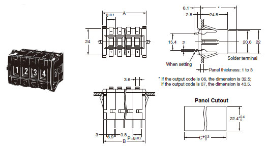
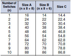
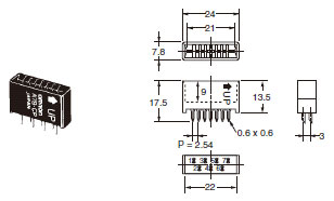
![A7BS / A7BL Dimensions 3 A7BS-2[][](-1)_Dim](upload/Images/omron/a7bs_a7bl_dm_121-111936.jpg)
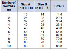
Note:Note:
Note:The dimensions above include both End Caps, and will increase 8 mm for each Spacer inserted.
Note:Unless otherwise specified, a tolerance of ±0.4 mm applies to all dimensions.
The tolerance for multiple connection is ±(number of units x 0.4) mm.
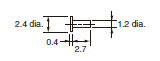
Use A7BS-S Stopper Pins to make dial display restrictions for these Switches.
Insert the Stopper Pins in the positions required to give the desired display range. For example, for a display range of 0 to 5, insert a Stopper Pin at position 1 (see following diagram) to stop the display from going above 5 when the (+) button is pressed, and insert a Stopper Pin at position 2 to stop the display from going below 0 when the (-) button is pressed.
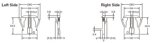
![A7BS / A7BL Dimensions 10 A7BS-20[]-S(-1)_Dim](upload/Images/omron/355_dm_321-111940.gif)
Note:If the output code is 06, the dimension is 32.5;
if the output code is 07, the dimension is 43.5.
Note:Note:
Note:Two pins constitute one set.
Note:The first shipment is free and is attached to the Switch.
Order the A7BS-S separately if it is required for maintenance.
Note:Note:
Note:The dimensions above include both End Caps, and will increase 8 mm for each Spacer inserted.
Note:Unless otherwise specified, a tolerance of ±0.4 mm applies to all dimensions.
The tolerance for multiple connection is ±(number of units x 0.4) mm.
_Dim](upload/Images/omron/a7bs_a7bl_dm_821-111950.jpg)
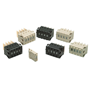
Note:The [] in the Spacer model number stands for a letter in the range A to U. (Refer to the table under the explanation about Spacers on Lineup.)
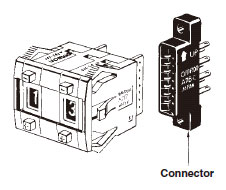
Note:(These devices allow Switches to be quickly removed for maintenance and inspection of connectivity, and quickly re-installed.)
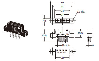
Insert Connectors with the "UP" arrow pointing up.
Note:Unless otherwise indicated, dimensional tolerances for dimensions in the models above are ± 0.4 mm.