Automation Systems
  Motion & Power Solutions
  Safety, Vision and IDENT
  Sensing Solutions
  Control Components
  Switching & Accessories
  Switchgear and Trolley Systems
  Process Weighing
  LED Lighting
  Omron
Omron
 Mitsubishi
 Delta
Delta
 Autonics
 Inno
Inno
 Panasonic
 Novotechnik
 Orientalmotor
 Microscan
 IPA
IPA
 Technomech
 Intech
 Honeywell
 IOT & Traceability
 Project & Panel Engg.
 Application Case Studies
 Solutions by Industry
 Solutions by Process
 Solutions by Product
 Youtube Videos
 Corporate Information
 Company Profile
 Quality Policy
 Mission Statement
 Chairman's Message
 Intech Group Companies

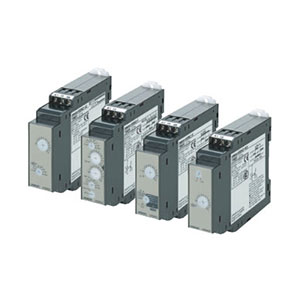
Compact Industrial SCARA
Compact Industrial Robot with light weight space saving arm. Its high speed operation is best suited for pick and place, labelling, tracking

last update: April 3, 2017
| S Series | L Series | |||
|---|---|---|---|---|
| Time range setting | x0.1 | x1 | x1 | x10 |
| Set time range | 0.1 to 1.2 s | 1 to 12 s | 1 to 12 s | 10 to 120 s |
| Power ON time | 0.1 s min. | 0.3 s min. | ||
| Scale numbers | 12 | |||
Note: The Timer will not operate if the specified power-on time is not kept. Be sure to supply power for at least the period specified. Also, make sure that the repeat cycle for the timing-out operation is at least 3 s.
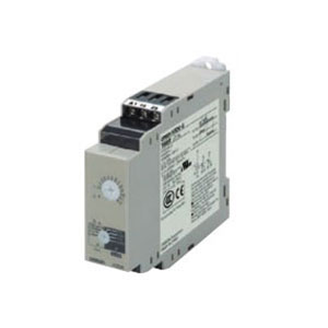
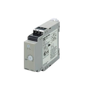
| Supply voltage |
100 to 120 VAC, 50/60 Hz 200 to 240 VAC, 50/60 Hz 24 to 48 VAC/DC, 50/60 Hz *1 |
|
|---|---|---|
| Allowable voltage fluctuation range | 85% to 110% of rated voltage | |
|
Power consumption |
H3DK-HCS/-HCL | At 120 VAC: 11.7 VA max. |
| H3DK-HDS/-HDL | At 240 VAC: 29.5 VA max. | |
| H3DK-HBS/-HBL | At 48 VAC: 1.2 VA max. *2 | |
| Control output |
Contact output, 5 A at 250 VAC with resistive load (cosφ = 1), 5 A at 30 VDC with resistive load *2 Contact materials: Ag-alloy |
|
| Ambient operating temperature | -20 to 55°C (with no icing) | |
| Storage temperature | -40 to 70°C (with no icing) | |
| Ambient operating humidity | 25% to 85% | |
*1. DC ripple: 20% max. (A single-phase, full-wave rectifying power supply can be connected.)
*2. Refer to DC Power Consumptions (Reference Information) on Catalog for DC power consumptions.
*3. The control output ratings are for one H3DK operating alone.
If you operate two or more Timers side by side, refer to Installation Pitch and Output Switching Capacity (Reference
Values) on the Catalog.
| Accuracy of operating time | ±1% of FS max. (±1% ±10 ms max. at 1.2-s range) | |
|---|---|---|
| Setting error | ±10% of FS ±0.05 s max. | |
| Influence of voltage | ±0.5% of FS max. (±0.5% ±10 ms max. at 1.2-s range) | |
| Influence of temperature | ±2% of FS max. (±2% ±10 ms max. at 1.2-s range) | |
| Insulation resistance | 100 MΩ min. at 500 VDC | |
| Dielectric strength |
Between current-carrying metal parts and exposed non-current-carrying metal parts: 2,000 VAC 50/60 Hz for 1 min. Between control output terminals and operating circuit: 2,000 VAC 50/60 Hz for 1 min. Between contacts not located next to each other: 1,000 VAC 50/60 Hz for 1 min. |
|
| Impulse withstand voltage |
Between power supply terminals: 1 kV for 24-VAC/DC and 48-VAC/DC models, 5 kV for all other models. Between current-carrying metal parts and exposed non-current-carrying metal parts): 1.5 kV for 24-VAC/DC and 48-VAC/DC models, 5 kV for all other models. |
|
| Noise immunity |
Square-wave noise generated by noise simulator (pulse width: 100 ns/1 μs, 1-ns rise): ±1.5 kV (between power supply terminals) |
|
| Static immunity | Malfunction: 4 kV, Destruction: 8 kV | |
|
Vibration resistance |
Destruction | 0.75-mm single amplitude at 10 to 55 Hz for 2 h each in 3 directions |
| Malfunction | 0.5-mm single amplitude at 10 to 55 Hz for 10 min each in 3 directions | |
|
Shock resistance |
Destruction | 1,000 m/s2 3 times each in 6 directions |
| Malfunction | 100 m/s2 3 times each in 6 directions | |
|
Life expectancy |
Mechanical | 10 million operations min. (under no load at 1,200 operations/h) |
| Electrical | 100,000 operations min. (5 A at 250 VAC, resistive load at 1,200 operations/h) | |
| Degree of protection | IP30 (Terminal block: IP20) | |
| Weight | Approx. 120 g | |
The relation between the installation pitch and the load current is shown in the following graph. (Except for the H3DK-GE) If Timer is used under load conditions that exceed the specified values, the temperature inside the Timer will increase, reducing the life expectancy of internal parts.
Tested Timer: H3DK-H
Applied voltage: 240 VAC
Installation pitch: 0, 5, 10, and 50 mm
| Safety standards |
cURus: UL 508/CSA C22.2 No. 14 EN 50274: Finger protection, back-of-hand proof EN 61812-1: Pollution degree 2, Overvoltage category III CCC: Pollution degree 2, Overvoltage category II, section DB14048.5-2008 part 5-1 LR: Test Specification No. 1-2002 Category ENV 1.2 |
|---|---|
| EMC |
(EMI)EN61812-1 Radiated Emissions:EN 55011 class B Emission AC Mains:EN 55011 class B Harmonic Current:EN 61000-3-2 Voltage Fluctuations and Flicker:EN61000-3-3 (EMS)EN61812-1 Immunity ESD: IEC61000-4-2 Immunity RF-interference: IEC61000-4-3 Immunity Burst: IEC61000-4-4 Immunity Surge: IEC61000-4-5 Immunity Conducted Disturbance: IEC61000-4-6 Immunity Voltage Dip/Interruption: IEC61000-4-11 |
| Input | None | |
|---|---|---|
| Output | Control output |
The Timer operates as soon as the Timer is turned ON. The Timer starts timing when the power is turned OFF and the output is turned OFF when the time set on the dial elapses. |
last update: April 3, 2017