Automation Systems
  Motion & Power Solutions
  Safety, Vision and IDENT
  Sensing Solutions
  Control Components
  Switching & Accessories
  Switchgear and Trolley Systems
  Process Weighing
  LED Lighting
  Omron
Omron
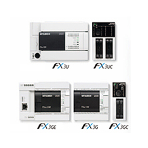
 Mitsubishi
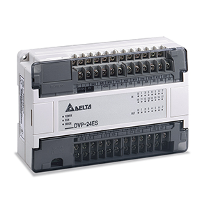
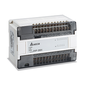
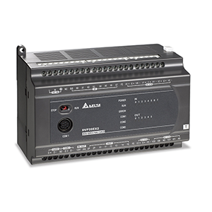
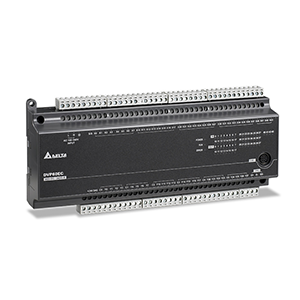
 Delta
Delta
 Autonics
 Inno
Inno
 Panasonic
 Novotechnik
 Orientalmotor
 Microscan
 IPA
IPA
 Technomech
 Intech
 Honeywell
 IOT & Traceability
 Project & Panel Engg.
 Application Case Studies
 Solutions by Industry
 Solutions by Process
 Solutions by Product
 Youtube Videos
 Corporate Information
 Company Profile
 Quality Policy
 Mission Statement
 Chairman's Message
 Intech Group Companies

Compact Industrial SCARA
Compact Industrial Robot with light weight space saving arm. Its high speed operation is best suited for pick and place, labelling, tracking
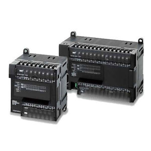

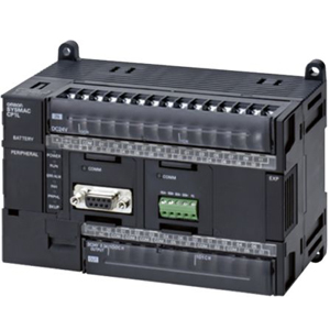
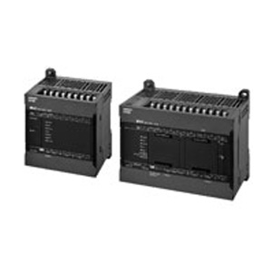
The CP1E provide high cost performance to further reduce costs by allowing you to select the optimal CPU Unit from the E[][]S-type Basic Models or N/[][]S(1)-type Application Models.
Windows is registered trademarks of Microsoft Corporation in the USA and other countries.
Other company names and product names in this document are the trademarks or registered trademarks of their respective companies.
Intuitive control with “Smart Input.”
When you begin typing an instruction from the keyboard in Ladder Editor Mode,suggested instructions are displayed and the addresses are automatically entered.
Connecting lines are added automatically based on the cursor position, enabling intuitive ladder programming.
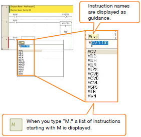
When you begin typing an instruction from the keyboard while in the Ladder Editor Window, suggested instructions are displayed. All you have to do is select the instruction from the list for easy input even if you do not remember the entire mnemonic.
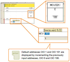
The address of the next operand, including input bits and output bits, is incremented by one and displayed as the default. This enables easily inputting consecutive addresses.
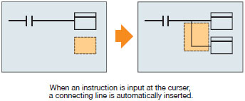
With the automatic connecting line insertion function the necessary connection is added automatically based on the curser position.
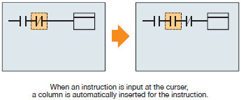
The column is automatically inserted when an instruction is added even if the curser is above another instruction.
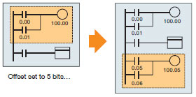
To create the same group of ladder instructions more than once with the address addition copy function, the instructions can be reused simply by inputting an address offset.
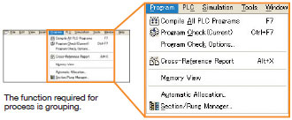
An intuitively designed menu structure makes it easy to see the overall system simply by looking at the menu for smooth operation without referring to a manual.
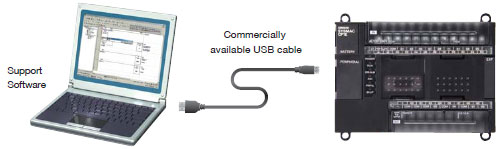
All CP1E CPU Units use high-speed USB for the peripheral port. Support software (computers) can be connected using commercially available USB cables. Without the need for USB conversion cables or special cables, connection is easier and cable cost is low.
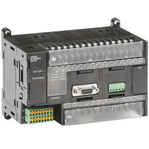
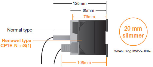
6 mm slimmer than the normal type.
Flexibly handle even small-scale systems.
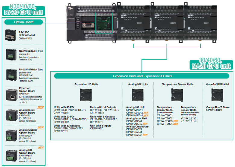
Various Option Units available for increased expandability.
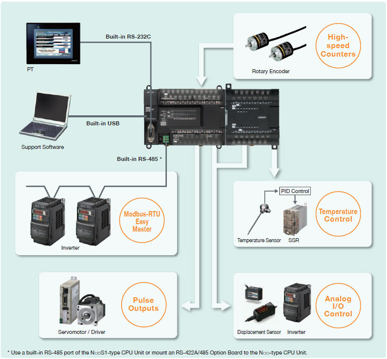
The Application Models (CP1E-N[][]/N[][]S(1)) are equipped with high-speed counters, pulse outputs, and a built-in serial port(s).
In addition, using the Expansion Unit and Option Board, you can control a wide range of devices.
Two 100kHz pulse outputs for high-precision position control.
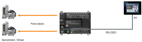
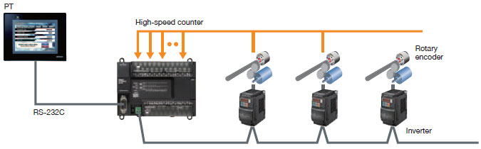
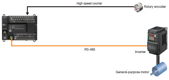
Control multiple axes with one PLC using the two 100kHz and four 10kHz, single-phase high-speed counters.
* The Basic Models are equipped with six 10kHz, single-phase high-speed counters.
Specify Inverter speeds via RS-485
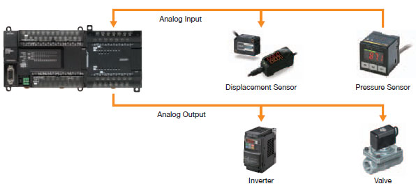
High-accuracy analog I/O control with a resolution 1/12,000.
You can add up to 4 analog I/O by mounting an Analog Option Board and up to 24 analog I/O by connecting Expansion Units.
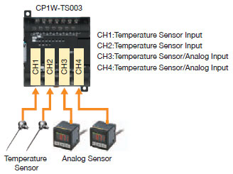
The combination of the Temperature Input Unit with the PID instructions enables temperature control.
Up to 12 thermocouple inputs per Unit for CP1W-TS004.
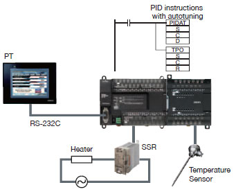
The CP1W-TS003 has two inputs that can be used for temperature sensor or analog inputs.
Both temperature sensor and analog inputs can be achieved with only one Unit.
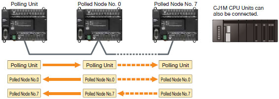
Link data with up to 10 words between up to nine CP1E-N CPU Units when controlling a device with multiple CP1E-N PLCs.
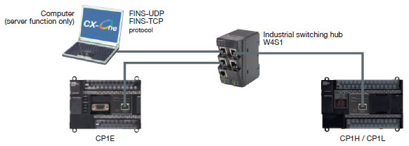
Mount a CP1W-CIF41 Ethernet Option Board to an option board slot on the CP1E-N/NA type CPU Unit.
Perform monitoring and programming with CX-Programmer or communicate with a host computer via Ethernet (server function only).
An option board for an additional Serial or Ethernet communication port can be added to the N30/40/60 and NA20 CPU Unit. Three expansion units are available.
* The Option Board cannot be mounted to the CP1E-N□□S/N□□S1.