Automation Systems
  Motion & Power Solutions
  Safety, Vision and IDENT
  Sensing Solutions
  Control Components
  Switching & Accessories
  Switchgear and Trolley Systems
  Process Weighing
  LED Lighting
  Omron
Omron
 Mitsubishi
 Delta
Delta
 Autonics
 Inno
Inno
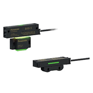
 Panasonic
 Novotechnik
 Orientalmotor
 Microscan
 IPA
IPA
 Technomech
 Intech
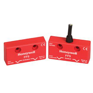
 Honeywell
 IOT & Traceability
 Project & Panel Engg.
 Application Case Studies
 Solutions by Industry
 Solutions by Process
 Solutions by Product
 Youtube Videos
 Corporate Information
 Company Profile
 Quality Policy
 Mission Statement
 Chairman's Message
 Intech Group Companies

Compact Industrial SCARA
Compact Industrial Robot with light weight space saving arm. Its high speed operation is best suited for pick and place, labelling, tracking
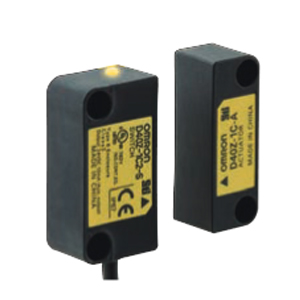

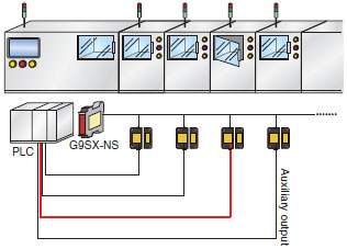
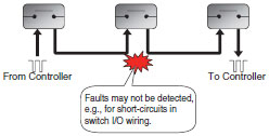
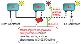
OMRON's unique electromagnetic induction system for safety was achieved by implementing a detection function for external wiring errors in the Switch.
The thorough pursuit of safety is evident in mutual checking by double CPUs.
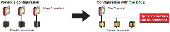
The D40Z can be connected to G9SP or G9SX-NS[] Safety Controllers. Select the best model for your application.
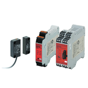
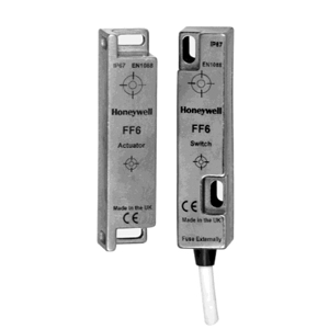
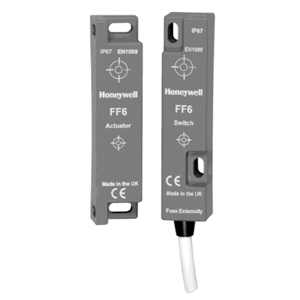
With these electronic switches, stable detection is possible even when the door closes slowly.
Permanent magnets are not used, so iron is not attracted, making maintenance easier.
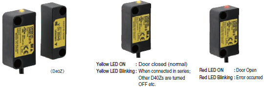
The switch's LED indication patterns make identification of abnormal condition possible at the production sites.
Note: For more information, refer to Catalog.
Bipolar NPN/PNP allows for easy connection with any PLC.
The error location can be easily identified. Using a branch relay for a different pole is not required.