Automation Systems
  Motion & Power Solutions
  Safety, Vision and IDENT
  Sensing Solutions
  Control Components
  Switching & Accessories
  Switchgear and Trolley Systems
  Process Weighing
  LED Lighting
  Omron
Omron
 Mitsubishi
 Delta
Delta
 Autonics
 Inno
Inno
 Panasonic
 Novotechnik
 Orientalmotor
 Microscan
 IPA
IPA
 Technomech
 Intech
 Honeywell
 IOT & Traceability
 Project & Panel Engg.
 Application Case Studies
 Solutions by Industry
 Solutions by Process
 Solutions by Product
 Youtube Videos
 Corporate Information
 Company Profile
 Quality Policy
 Mission Statement
 Chairman's Message
 Intech Group Companies

Compact Industrial SCARA
Compact Industrial Robot with light weight space saving arm. Its high speed operation is best suited for pick and place, labelling, tracking
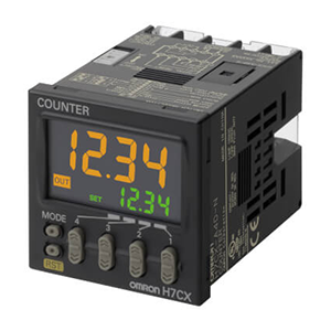

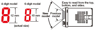
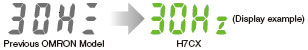
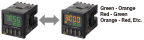
The larger characters and wider viewing angle join a bright display for easy reading even in well-lit locations.
We increased the number of display segments to make setting parameters even easier.
Using green when output is OFF using orange when output is ON
*Display colors can be switched only on models with terminal blocks.
The shorter body enables mounting in thin control panels.
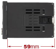
At only 59 mm, the shortest body for any industrial counter.
At only 78 mm, the shortest body for any industrial counter that isolates the power supply and input circuits.
*Models with sockets: 63.7 mm (case dimension)
The above claims apply to counters with a maximum ambient temperature of 55 ºC.
According to OMRON investigations June 2009.
Restricting the set time help prevent incorrect settings.
The number of times that the control output turns ON is counted and an alarm is displayed when a preset count is exceeded.
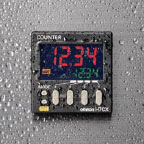
A Twin counter mode has been added to enable using two counters with only one unit.
*Only two-stage models.
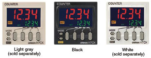
Replace the front panel with an Optional Front Panel to change the basic color from black to light gray or white.
• Optional Front Panels let you match the color of the panel or surrounding devices.
Worry-free application is possible in locations subject to water.
*When the Y92S-29 waterproof packing is used.
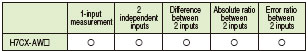
New input modes have been added to the new models.
Now you can handle a wider range of applications.
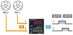
(1) One-input measurement
Measurement operation with one input.
Select the HI-LO, AREA, HI-HI, or LO-LO output mode.
(2) Independent Measurement for Two Inputs Measurement operation with two independent inputs.
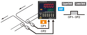
(3) Differential Input for Two Inputs Measuring the difference between two inputs (CP1 - CP2).
(4) Absolute ratio for two inputs measuring the ratio between two inputs (CP1/CP2).
(5) Error ratio between two inputs measuring the ratio between two inputs ((CP1-CP2)/CP2)).
last update: December 01, 2015
| Models | H7CX-A114[]-N | H7CX-A11[]-N | H7CX-A4[]-N | |
|---|---|---|---|---|
| Classification | Preset counter | |||
| Configuration | 1-stage preset counter, 1-stage preset counter with total counter (selectable) *1 | |||
| Ratings |
Power supply voltage*2 |
100 to 240 VAC, 50/60 Hz 24 VAC, 50/60 Hz or 12 to 24 VDC |
100 to 240 VAC, 50/60 Hz 12 to 24 VDC |
|
|
Operating voltage fluctuation range |
85% to 110% of rated supply voltage (12 to 24 VDC: 90% to 110%) | |||
|
Power consumption |
Approx. 9.4 VA at 100 to 240 VAC, Approx. 7.2 VA/4.7 W at 24 VAC/12 to 24 VDC, Approx. 3.7 W at 12 to 24 VDC |
|||
| Mounting method | Flush mounting or surface mounting | Flush mounting | ||
| External connections | 11-pin socket | Screw terminals | ||
| Degree of protection |
IEC IP66, UL508 Type 4X (indoors) for panel surface only and only when Y92S-29 Waterproof Packing is used. |
|||
| Input signals | CP1, CP2, reset, and total reset | |||
| Counter |
Maximum counting speed |
30 Hz (minimum pulse width: 16.7 ms) or 10 kHz (minimum pulse width: 0.05 ms) (selectable) (ON/OFF ratio 1:1) *Common setting for CP1 and CP2 |
||
| Input mode |
Increment, decrement, increment/decrement (UP/DOWN A (command input), UP/DOWN B (individual inputs), or UP/DOWN C (quadrature inputs)) |
|||
| Output mode | N, F, C, R, K-1, P, Q, A, K-2, D, and L. | |||
|
One-shot output time |
0.01 to 99.99 s | |||
| Reset system |
External (minimum reset signal width: 1 ms or 20 ms, selectable), manual, and automatic reset (internal according to C, R, P, and Q mode operation) |
|||
| Tachometer | Refer to the separate table for tachometer function ratings. | |||
| Prescaling function | Yes (0.001 to 9.999) | Yes (0.001 to 99.999) | Yes (0.001 to 9.999) | |
| Decimal point adjustment | Yes (rightmost 3 digits) | |||
| Sensor waiting time |
290 ms max. (Control output is turned OFF and no input is accepted during sensor waiting time.) |
|||
| Input method |
No-voltage inputs: ON impedance: 1 kΩ max. (Leakage current: 12 mA at 0 Ω) ON residual voltage: 3 V max. OFF impedance: 100 kΩ min. Voltage input: High (logic) level: 4.5 to 30 VDC Low (logic) level: 0 to 2 VDC (Input resistance: approx. 4.7 kΩ) No-voltage input/voltage input (selectable) |
|||
| External power supply | 12 VDC (±10%), 100 mA (except for H7CX-A[]D models) Refer to on page for details. | |||
| Control output |
Contact output: 3 A at 250 VAC/30 VDC, resistive load (cosφ=1), Minimum applied load: 10 mA at 5 VDC (failure level: P, reference value) Transistor output: NPN open collector, 100 mA at 30 VDC, Residual voltage: 1.5 VDC max. (approx. 1 V), Leakage current: 0.1 mA max. |
|||
| Display*3 |
7-segment, negative transmissive LCD Character height Count value: 12 mm (red) Set value: 6 mm (green) |
7-segment, negative transmissive LCD Character height Count value: 10 mm (red) Set value: 6 mm (green) |
7-segment, negative transmissive LCD Character height Count value: 12 mm (red, green, or orange selectable) Set value: 6 mm (green) |
|
| Digits |
4 digits -999 to 9999 (-3 digits to +4 digits) |
6 digits -99999 to 999999 (-5 digits to +6 digits) |
4 digits -999 to 9999 (-3 digits to +4 digits) |
|
| Memory backup | EEPROM (overwrites: 100,000 times min.) that can store data for 10 years min. | |||
|
Operating temperature range |
-10 to 55°C (-10 to 50°C if Counter/Tachometers are mounted side by side) (with no icing or condensation) |
|||
| Storage temperature range | -25 to 70°C (with no icing or condensation) | |||
| Operating humidity range | 25% to 85% | |||
| Case color |
Black (N1.5) (Optional Front Panels are available to change the Front Panel color to light gray or white.) |
|||
| Attachments | --- |
Flush mounting adapter, waterproof packing, terminal cover |
||
| Models | H7CX-A[]-N | H7CX-A4W[]-N | H7CX-AW[]-N/-AU[]-N | |
|---|---|---|---|---|
| Classification | Preset counter | Preset counter/tachometer | ||
| Configuration |
1-stage preset counter, 1-stage preset counter with total counter (selectable) *1 |
1-stage/2-stage preset counter, total and preset counter *1, batch counter, dual counter, and twin counter (selectable) |
1-stage/2-stage preset counter, total and preset counter *1, batch counter, dual counter, twin counter, and tachometer (selectable) |
|
| Ratings |
Power supply voltage*2 |
100 to 240 VAC, 50/60 Hz 12 to 24 VDC |
100 to 240 VAC at 50/60 Hz 24 VAC at 50/60 Hz or 12 to 24 VDC 12 to 24 VDC |
|
|
Operating voltage fluctuation range |
85% to 110% of rated supply voltage (12 to 24 VDC: 90% to 110%) | |||
|
Power consumption |
Approx. 9.4 VA at 100 to 240 VAC, Approx. 7.2 VA/4.7 W at 24 VAC/12 to 24 VDC, Approx. 3.7 W at 12 to 24 VDC |
|||
| Mounting method | Flush mounting | |||
| External connections | Screw terminals | |||
| Degree of protection |
IEC IP66, UL508 Type 4X (indoors) for panel surface only and only when Y92S-29 Waterproof Packing is used. |
|||
| Input signals |
CP1, CP2, reset, and total reset |
CP1, CP2, reset 1, and reset 2 | ||
| Counter |
Maximum counting speed |
30 Hz (minimum pulse width: 16.7 ms) or 10 kHz (minimum pulse width: 0.05 ms) (selectable) (ON/OFF ratio 1:1) *Common setting for CP1 and CP2 |
||
| Input mode |
Increment, decrement, increment/decrement (UP/DOWN A (command input), UP/DOWN B (individual inputs), or UP/DOWN C (quadrature inputs)) |
|||
| Output mode |
N, F, C, R, K-1, P, Q, A, K-2, D, and L. |
N, F, C, R, K-1, P, Q, A, K-2, D, L, and H. | ||
|
One-shot output time |
0.01 to 99.99 s | |||
| Reset system |
External (minimum reset signal width: 1 ms or 20 ms, selectable), manual, and automatic reset (internal according to C, R, P, and Q mode operation) |
|||
| Tachometer | Refer to the separate table for tachometer function ratings. | |||
| Prescaling function | Yes (0.001 to 99.999) | Yes (0.001 to 9.999) | Yes (0.001 to 99.999) | |
| Decimal point adjustment | Yes (rightmost 3 digits) | |||
| Sensor waiting time |
290 ms max. (Control output is turned OFF and no input is accepted during sensor waiting time.) |
|||
| Input method |
No-voltage inputs: ON impedance: 1 kΩ max. (Leakage current: 12 mA at 0 Ω) ON residual voltage: 3 V max. OFF impedance: 100 kΩ min. Voltage input: High (logic) level: 4.5 to 30 VDC Low (logic) level: 0 to 2 VDC (Input resistance: approx. 4.7 kΩ) No-voltage input/voltage input (selectable) |
|||
| External power supply | 12 VDC (±10%), 100 mA (except for H7CX-A[]D models) Refer to on page for details. | |||
| Control output |
Contact output: 3 A at 250 VAC/30 VDC, resistive load (cosφ=1), Minimum applied load: 10 mA at 5 VDC (failure level: P, reference value) Transistor output: NPN open collector, 100 mA at 30 VDC, Residual voltage: 1.5 VDC max. (approx. 1 V), Leakage current: 0.1 mA max. |
|||
| Display*3 |
7-segment, negative transmissive LCD Character height Count value: 10 mm (red, green, or orange selectable) Set value: 6 mm (green) |
7-segment, negative transmissive LCD Character height Count value: 12 mm (red, green, or orange selectable) Set value: 6 mm (green) |
7-segment, negative transmissive LCD Character height Count value: 10 mm (red, green, or orange selectable) Set value: 6 mm (green) |
|
| Digits |
6 digits -99999 to 999999 (-5 digits to +6 digits) |
4 digits -999 to 9999 (-3 digits to +4 digits) |
6 digits -99999 to 999999 (-5 digits to +6 digits), tachometer: 0 to 999999 |
|
| Memory backup | EEPROM (overwrites: 100,000 times min.) that can store data for 10 years min. | |||
|
Operating temperature range |
-10 to 55°C (-10 to 50°C if Counter/Tachometers are mounted side by side) (with no icing or condensation) |
|||
| Storage temperature range | -25 to 70°C (with no icing or condensation) | |||
| Operating humidity range | 25% to 85% | |||
| Case color |
Black (N1.5) (Optional Front Panels are available to change the Front Panel color to light gray or white.) |
|||
| Attachments |
Flush mounting adapter, waterproof packing, terminal cover |
Flush mounting adapter, waterproof packing, terminal cover, label for DIP switch settings |
||
*1. 1-stage preset counter and total counter functionality.
*2. Do not use the output from an inverter as the power supply.The ripple must be 20% maximum for DC power.
*3. The display is lit only when the power is ON. Nothing is displayed when power is OFF.
| Model |
H7CX-A114[]-N H7CX-A11[]-N H7CX-A4[]-N H7CX-A[]-N H7CX-A4W[]-N |
H7CX-AW[]-N/-AU[]-N | |||
|---|---|---|---|---|---|
| Input mode |
No tachometer functionality |
Selectable from independent measurements for 1 or 2 inputs, differential input for 2 inputs, absolute ratio for 2 inputs, and error ratio for 2 inputs. |
|||
|
Pulse measurement method |
Periodic measurement | Pulse width measurement | |||
|
Maximum counting speed |
30 Hz (minimum pulse width: 16.7 ms) |
1-input mode: 10 kHz (minimum pulse width: 0.05 ms) Other modes: 5 kHz (minimum pulse width: 0.1 ms) |
30 Hz (minimum pulse width: 16.7 ms) |
1-input mode: 10 kHz (minimum pulse width: 0.05 ms) Other modes: 5 kHz (minimum pulse width: 0.1 ms) |
|
|
Minimum input signal width |
--- | --- | 30 ms *1 |
1-input mode: 0.2 ms Other modes: 0.4 ms * |
|
|
Measuring ranges |
0.001 to 30.00 Hz |
1-input mode: 0.001 to 10 kHz, Other modes: 0.01 to 5 kHz |
0.030 to 999999 s |
1-input mode: 0.0002 to 99999 s Other modes: 0.0004 to 99999 s |
|
| Sampling period | 200 ms min. |
200 ms min. or continuous selectable (minimum interval of 10 ms) |
Continuous (minimum interval of 10 ms) |
||
|
Measuring accuracy |
±0.1% FS ±1 digit max. (at 23 ±5°C) | ||||
| Output mode |
Input mode: Not 2-input independent measurement: HI-LO, AREA, HI-HI, LO-LO 2-input independent measurement: HI-HI, LO-LO |
||||
| Auto-zero time | 0.1 to 999.9s | ||||
| Startup time | 0.0 to 99.9s | ||||
| Averaging |
Simple averaging/moving averaging selectable, Processing: OFF, 2, 4, 8, or 16 times |
||||
| Hold input | Minimum input signal width: 20 ms | ||||
| Insulation resistance |
100 MΩ min. (at 500 VDC) between current-carrying terminals and exposed non-current- carrying metal parts, and between non-continuous contacts |
|
|---|---|---|
| Dielectric strength |
2,000 VAC, 50/60 Hz for 1 min between current-carrying metal parts and non-current- carrying metal parts 2,000 VAC, 50/60 Hz for 1 min between power supply and input circuit for all models except H7CX-[]D[] (1,000 VAC for 24 VAC/12 to 24 VDC) 1,000 VAC (for H7CX-[]SD[]), 50/60 Hz for 1 min between control output, power supply, and input circuit (2,000 VAC for models other than H7CX-[]SD[]) 1,000 VAC, 50/60 Hz for 1 min between non-continuous contacts |
|
| Impulse withstand voltage |
3.0 kV between power terminals (1.0 kV for models with 24 VAC/12 to 24 VDC or 12 to 24 VDC) 4.5 kV between current-carrying terminals and exposed non-current-carrying metal parts (1.5 kV for models with 24 VAC/12 to 24 VDC or 12 to 24 VDC) |
|
| Noise immunity |
±1.5 kV between power terminals (±480 V for models with 12 to 24 VDC) ±600 V between input terminals Square-wave noise by noise simulator (pulse width: 100 ns/1 μs, 1-ns rise) |
|
| Static immunity | Malfunction: 8 kV Destruction: 15 kV | |
|
Vibration resistance |
Destruction | 10 to 55 Hz with 0.75-mm single amplitude each in three directions for 2 h each |
| Malfunction | 10 to 55 Hz with 0.35-mm single amplitude each in three directions for 10 min each | |
|
Shock re-sistance |
Destruction | 300 m/s2 each in three directions |
| Malfunction | 100 m/s2 each in three directions | |
| Life expectancy |
Mechanical: 10,000,000 operations min. Electrical: 100,000 operations min. (3 A at 250 VAC, resistive load, ambient temperature condition: 23°C) * |
|
| Weight | Approx. 130 g (Counter only) | |
A current of 0.15 A max. can be switched at 125 VDC (cosφ=1) and current of 0.1 A max. can be switched if L/R=7 ms. In both cases, a life of 100,000 operations can be expected.
|
Approved safety standards |
cULus (or cURus): UL508/CSA C22.2 No. 14 *1 EN 61010-1 (IEC 61010-1): Pollution degree 2/overvoltage category II B300 PILOT DUTY 1/4 HP 120 VAC, 1/3 HP, 240 VAC, 3 A resistive load VDE0106/P100 (finger protection) |
|---|---|
| EMC |
(EMI) EN61326-1 *2 Emission Enclosure: EN 55011 Group 1 class A Emission AC mains: EN 55011 Group 1 class A (EMS) EN61326-1 *2 Immunity ESD: EN 61000-4-2: 4 kV contact discharge; 8 kV air discharge Immunity RF-interference: EN 61000-4-3: 10 V/m (Amplitude-modulated, 80 MHz to 1 GHz); 10 V/m (Pulse- modulated, 900 MHz ±5 MHz) Immunity Conducted Disturbance: EN 61000-4-6: 10 V (0.15 to 80 MHz) Immunity Burst: EN 61000-4-4: 2 kV power-line; 1 kV I/O signal-line Immunity Surge: EN 61000-4-5: 1 kV line to lines (power and output lines); 2 kV line to ground (power and output lines) Immunity Voltage Dip/Interruption: EN 61000-4-11: 0.5 cycle, 100% (rated voltage) |
*1. The following safety standards apply to models with sockets (H7CX-A11[] or H7CX-A114[]).
cUL (Listing): Applicable when an OMRON P2CF(-E) Socket is used.
cUR (Recognition): Applicable when any other socket is used.
*2. Industrial electromagnetic environment (EN/IEC 61326-1 Table 2)
| Inputs | CP1, CP2 |
(1) In general (except for Dual Counter Mode) Reads counting signals. Increment, decrement, command, individual, and quadrature inputs accepted. (2) When used as a dual counter or twin counter Reads CP1 count signals with CP1 input and CP2 count signals with CP2 input. Increment signals can be input. |
|---|---|---|
| Reset/reset 1 |
(1) In general (except for Dual Counter Mode) Resets present value and outputs (OUT2 when using the batch counter) *2. Counting cannot be performed during reset/reset 1 input. Reset indicator is lit while reset input is ON. (2) When used as a dual counter or twin counter. Resets the CP1 present value (to 0). Counting for CP1 input cannot be performed while the reset 1 input is ON. The reset indicator is lit while the reset 1 input is ON. |
|
| Total reset or reset 2 | The reset function depends on the selected configuration *3. | |
| Outputs | OUT1, OUT2 | Outputs signals according to the specified output mode when a set value is reached. |
*1. For information on operation of I/O functions, refer to Catalog.
*2. In increment mode or increment/decrement mode, the present value returns to 0; in decrement mode, the present value returns to the set value with 1-stage models, and returns to set value 2 with 2-stage models.
*3. Reset operates as described in the following table. (The reset indicator will not be lit.)
| Configuration | Reset operation |
|---|---|
| 1-stage/2-stage preset counter | Does not operate (not used). |
| Total and preset counter |
Resets the total count value. The total count value is held at 0 while the total reset input is ON. |
| Batch counter |
Resets the batch count value and batch output (OUT1). The batch count value is held at 0 while the reset 2 input is ON. |
| Dual counter |
Resets the CP2 present value. Counting for CP2 input cannot be performed while the reset 2 input is ON. |
| Twin counter | Resets the CP2 present value. |
• The following table shows the delay from when the reset signal is input until the output is turned OFF. (Reference values)
| Minimum reset signal width | Output delay time |
|---|---|
| 1 ms | 0.8 to 1.2 ms |
| 20 ms | 15 to 25 ms |
| Inputs | CP1, CP2 |
Reads counting signals. (The CP2 input can be used when the input mode is not 1-input mode.) |
|---|---|---|
| Reset/reset 1 |
Holds the measurement value and outputs. (The reset 2 input can be used when the input mode is 2-input independent measurement.) Functions as a hold input. The measurement value (displayed value) and the outputs are held while the RST Key on the front panel is pressed. The reset indicator is lit when the value is being held. |
|
| Outputs | OUT1, OUT2 | Outputs signals according to the specified output mode when a set value is reached. |
Note: M3.5 terminal screw (effective length: 6 mm)
Note: M3.5 terminal screw (effective length: 6 mm)
Note: 1. The mounting panel thickness should be 1 to 5 mm.
Note: 2. To allow easier operation, it is recommended that Adapters be mounted so that the gap between sides with hooks is at least 15 mm (i.e., with the panel cutouts separated by at least 60 mm).
Note: 3. It is possible to horizontally mount Timers side by side. Attach the Flush Mounting Adapters so that the surfaces without hooks are on the sides of the Timers. If they are mounted side-byside, water-resistance will be lost.
* These dimensions depend on the kind of DIN Track. (Reference value)