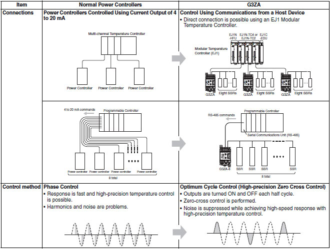
Note: The G3ZA must be used in combination with an SSR without the zero cross function when the soft-start function is used.
last update: September 24, 2012
|
Load power supply voltage range |
100 to 240 VAC | 400 to 480 VAC |
|---|---|---|
| Power supply voltage | 100 to 240 VAC (50/60 Hz) | |
| Operating voltage range | 85 to 264 VAC | |
| Power consumption | 16 VA max. | |
| Load power supply voltage | 100 to 240 VAC | 400 to 480 VAC |
| Load power supply voltage range | 75 to 264 VAC | 340 to 528 VAC |
| Manipulated variable input | 0.0% to 100.0% (via RS-485 communications) | |
| Current transformer input *1 |
Single-phase AC, 0 to 50 A (primary current of CT) Single-phase AC, 0 to 150 A (primary current of CT) |
|
| Trigger output |
One voltage output for each channel, 12 VDC ±15%, Max. load current: 21 mA (with built-in short-circuit protection circuit) |
|
| Alarm output |
NPN open collector, one output Max. applicable voltage: 30 VDC, Max. load current: 50 mA Residual voltage: 1.5 V max., Leakage current: 0.4 mA max. |
|
| Indications | LED indicators | |
| Control method |
Optimum cycle control Soft-start optimum cycle control *2 Three-phase optimum cycle control |
|
| Ambient operating temperature | -10 to 55°C (with no icing or condensation) | |
| Ambient operating humidity | 25% to 85% | |
| Storage temperature | -25 to 65°C (with no icing or condensation) | |
| Elevation | 2,000 m max. | |
| Accessories | Instruction Sheet | |
*1. CT inputs are provided only on Models with heater burnout detection.
*2. Use an SSR without the zero-cross function (G3PA-[]BL-VD) for soft-start optimum cycle control. (Refer to G3PA for
details.)
| Current indication accuracy |
Current Range 0 to 50 A, ±3 A 0 to 150 A, ±9 A 0 to 100%, ±6% * (for models with heater burnout detection) |
|---|---|
| Insulation resistance | 100 MΩ min. (at 500 VDC) between primary and secondary |
| Dielectric strength | 2,000 VAC, 50/60 Hz for 1 min between primary and secondary |
| Vibration resistance | Vibration frequency: 10 to 55 Hz, acceleration: 50 m/s2 in X, Y, and Z directions |
| Shock resistance | 300 m/s2 three times each in six directions along three axes |
| Weight | Approx. 200 g (including terminal cover) |
| Degree of protection | IP20 |
| Memory protection | EEPROM (non-volatile memory) (number of writes: 100,000) |
| Installation environment | Overvoltage category III, pollution degree 2 (according to IEC 60664-1) |
| Approved standards |
UL508 (Listing), CSA22.2 No. 14 EN50178 EN61000-6-4 (EN55011: 1998, A1: 1999 Class A, Group 1) EN61000-6-2: 2001 |
* When measured with percentage selected for the current monitor parameter and the maximum current measurable with the CT at 100%.
| Transmission line connections | Multipoint | |
|---|---|---|
| Communications method | RS-485 | |
| Max. transmission distance | 500 m | |
| No. of nodes | 31 (via multidrop connections) | |
| Synchronization method | Stop-start synchronization | |
| Communications baud rate | 9.6, 19.2, 38.4 or 57.6 kbps, Default: 9.6 kbps | |
| Transmission code | ASCII | |
| Communications data length | 7 or 8 bits, Default: 7 | |
| Communications stop bits | 1 or 2 bits, Default: 2 | |
| Communications parity | Vertical parity: None, even, or odd, Default: Even | |
| Flow control | None | |
| Item | Specification | ||
|---|---|---|---|
| Model number | E54-CT1 | E54-CT3 | G3ZA-CT150L |
| Max. continuous heater current | 50 A | 120 A * | 150 A |
| Detection current with G3ZA connected | 50 A | 150 A | |
| Dielectric strength | 1,000 VAC for 1 min | 2,000 VAC for 1 min | |
| Vibration resistance | 98 m/s2, 50 Hz | ||
| Weight | Approx. 11.5 g | Approx. 50 g | Approx. 130 g |
| Accessories | None |
Connection terminals (2) Plugs (2) |
None |
* The maximum continuous current is 50 A for the G3ZA in combination with the E54-CT3.
last update: September 24, 2012
Note: The G3ZA-CT150L is for use only in combination with the G3ZA (Ver.2.0 or higher).
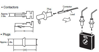
Wire terminal k and terminal l. (Do not use terminal kt and terminal lt.)
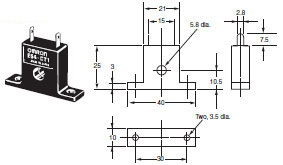
* Do not remove the attached resister.
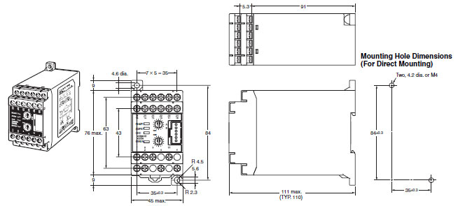
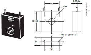
* Dimension in parentheses are for the PFP-50N.
| TITLE | DOCUMENT TYPE | SIZE |
| G3ZA | Catalog | 1198 KB |
|---|---|---|
|
G3ZA
Multi-channel power controller |
Manual | 2279 KB |
| Relay defects causes & solutions (SSR Edition) technical guide | Technical Guide | 6806 KB |
|
E54-CT1/CT3
Current transformer |
Instruction Manual | 67 KB |