Automation Systems
  Motion & Power Solutions
  Safety, Vision and IDENT
  Sensing Solutions
  Control Components
  Switching & Accessories
  Switchgear and Trolley Systems
  Process Weighing
  LED Lighting
  Omron
Omron
 Mitsubishi
 Delta
Delta
 Autonics
 Inno
Inno
 Panasonic
 Novotechnik
 Orientalmotor
 Microscan
 IPA
IPA
 Technomech
 Intech
 Honeywell
 IOT & Traceability
 Project & Panel Engg.
 Application Case Studies
 Solutions by Industry
 Solutions by Process
 Solutions by Product
 Youtube Videos
 Corporate Information
 Company Profile
 Quality Policy
 Mission Statement
 Chairman's Message
 Intech Group Companies


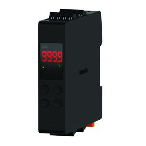
Compact Industrial SCARA
Compact Industrial Robot with light weight space saving arm. Its high speed operation is best suited for pick and place, labelling, tracking
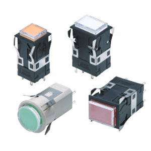

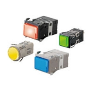
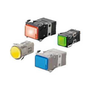
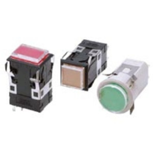
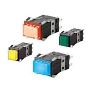
• Excellent operating sensitivity.
• Excellent illumination with even surface brightness.
• Three-color models (green, orange, red; chameleon lighting) included in lineup.
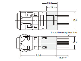
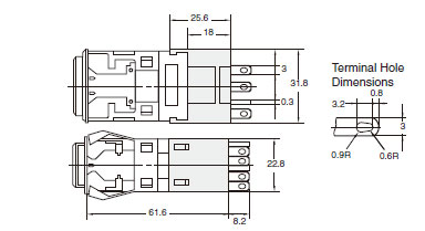
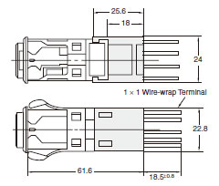
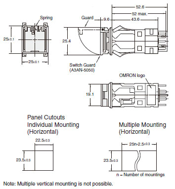
The Dimension shows 2-switch outputs.
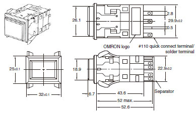
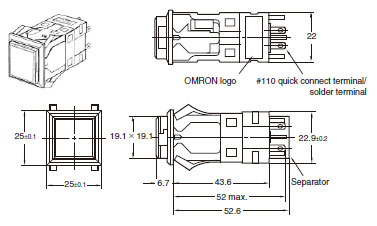
Note: The thickness of tab terminals #110 and solder terminals is 0.5 mm.
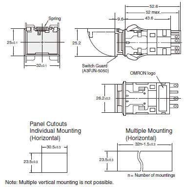
(If using a Switch Guard or Seal Cover, refer to the panel cutout diagrams on Data Sheet.)
Note: 1. n: Number of Units
2. Recommended panel thickness: 1 to 5 mm
3. Mount the panel before mounting the Switch Guard.
4. If the panel is to be finished (e.g., coated), make sure that the panel meets the specified dimensions after the
coating.
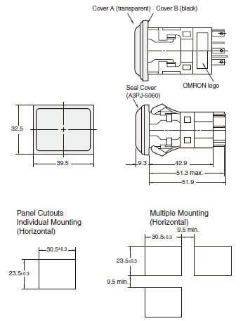
Note: 1. n: Number of Units
2. Recommended panel thickness: 1 to 5 mm
3. Mount the panel before mounting the Switch Guard.
4. If the panel is to be finished (e.g., coated), make sure that the panel meets the specified dimensions after the
coating.
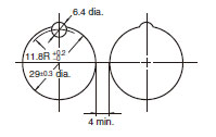
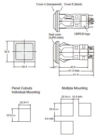
Note: 1. Recommended panel thickness: 1 to 5 mm
2. If the panel is to be finished (e.g., coated), make sure that the panel meets the specified dimensions after the
coating.
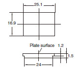
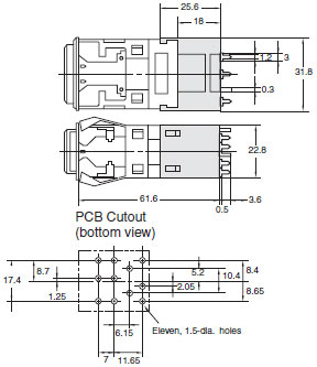
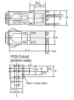
Note: PCB cutout dimensions show the switch mounted to the socket with the OMRON logo facing down.
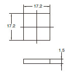
Note: 1. Recommended panel thickness: 1 to 5 mm
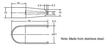
2. Unless otherwise specified, a tolerance of ± 0.4 mm applies to all dimensions.