Automation Systems
  Motion & Power Solutions
  Safety, Vision and IDENT
  Sensing Solutions
  Control Components
  Switching & Accessories
  Switchgear and Trolley Systems
  Process Weighing
  LED Lighting
  Omron
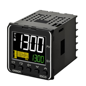
Omron
 Mitsubishi
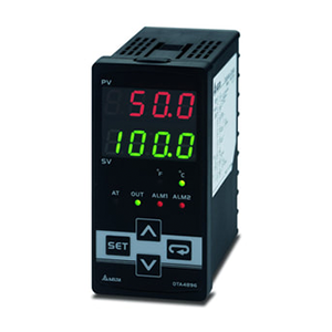
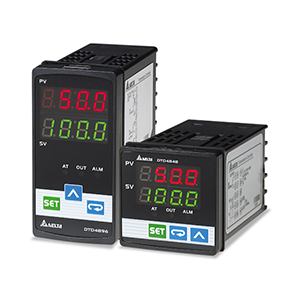
 Delta
Delta
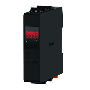
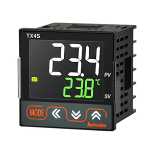
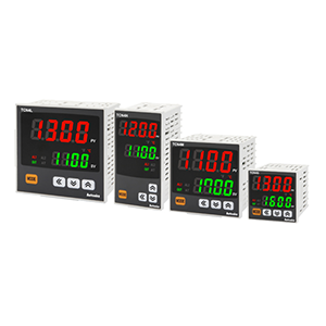
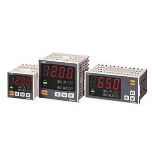
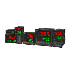
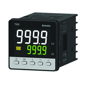
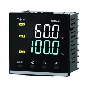
 Autonics
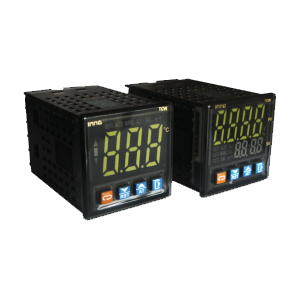
 Inno
Inno
 Panasonic
 Novotechnik
 Orientalmotor
 Microscan
 IPA
IPA
 Technomech
 Intech
 Honeywell
 IOT & Traceability
 Project & Panel Engg.
 Application Case Studies
 Solutions by Industry
 Solutions by Process
 Solutions by Product
 Youtube Videos
 Corporate Information
 Company Profile
 Quality Policy
 Mission Statement
 Chairman's Message
 Intech Group Companies

Compact Industrial SCARA
Compact Industrial Robot with light weight space saving arm. Its high speed operation is best suited for pick and place, labelling, tracking

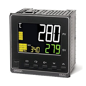
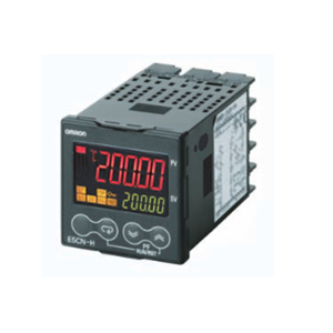
Indication Accuracy
Thermocouple input: ±0.3% of PV (previous models: ±0.5%)
Pt input: ±0.2% of PV (previous models: ±0.5%)
Analog input: ±0.2% FS (previous models: ±0.5%)
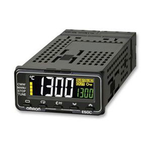
Models are available with screw terminal blocks or screwless clamp terminal blocks.
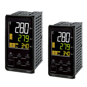
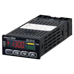
A PV/SV-status display function can be set to automatically alternate between displaying the status of the Temperature Controller (auto/manual, RUN/STOP, and alarms) and the PV or SV.
Preventive maintenance for relays in the Temperature Controller using a Control Output ON/OFF Counter.
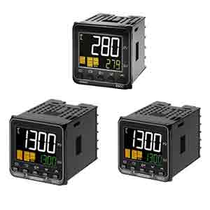
Switch the PV display between three colors.
Compatible with Support Software (CX-Thermo version 4.2 or higher).
Eleven-segment displays.
Models are available with one or two alarm outputs.
| Power supply voltage |
No D in model number: 100 to 240 VAC, 50/60 Hz D in model number: 24 VAC, 50/60 Hz; 24 VDC |
|
|---|---|---|
| Operating voltage range | 85% to 110% of rated supply voltage | |
|
Power consump- tion |
E5GN Screw terminal block |
100 to 240 VAC: 5.5 VA (max.) 24 VAC/VDC: 3 VA/2 W (max.) |
|
E5GN-[]-C Screwless clamp terminal block |
100 to 240 VAC: 5.5 VA (max.) 24 VAC/VDC: 3 VA/2 W (max.) |
|
| Sensor input |
Models with temperature inputs Thermocouple: K, J, T, E, L, U, N, R, S, B, W, or PL II Platinum resistance thermometer: Pt100 or JPt100 Infrared temperature sensor (ES1B): 10 to 70°C, 60 to 120°C, 115 to 165°C, or 140 to 260°C Voltage input: 0 to 50 mV |
|
|
Models with analog inputs Current input: 4 to 20 mA or 0 to 20 mA Voltage input: 1 to 5 V, 0 to 5 V, or 0 to 10 V |
||
| Input impedance | Current input: 150 Ω max., Voltage input: 1 MΩ min. (Use a 1:1 connection when connecting the ES2-HB.) | |
| Control method | ON/OFF control or 2-PID control (with auto-tuning) | |
|
Control outputs |
Relay output |
SPST-NO, 250 VAC, 2 A (resistive load), electrical life: 100,000 operations, minimum applicable load: 5 V, 10 mA |
|
Voltage output (for driving SSR) |
Output voltage: 12 VDC ± 15% (PNP), max. load current: 21 mA, with short-circuit protection circuit | |
| Current output | 4 to 20 mA DC/0 to 20 mA DC, load: 500 Ω max., resolution: approx. 10,000 | |
|
Auxiliary outputs |
Number of outputs | 1 or 2 max. (Depends on the model.) |
|
Output specifications |
Relay output: SPST-NO, 250 VAC, 2 A (resistive load), electrical life: 100,000 operations, minimum applicable load: 5 V, 10 mA |
|
|
Event inputs |
Number of inputs | 2 |
|
External contact input specifications |
Contact input: ON: 1 kΩ max., OFF: 100 kΩ min. | |
| Non-contact input: ON: Residual voltage: 1.5 V max., OFF: Leakage current: 0.1 mA max. | ||
| Current flow: Approx. 7 mA per contact | ||
| Setting method | Digital setting using front panel keys | |
| Indication method |
11-segment digital display and individual indicators (7-segment display also possible) Character height: PV: 7.5 mm, SV: 3.6 mm |
|
| Multi SP |
Up to four set points (SP0 to SP3) can be saved and selected using event inputs, key operations, or serial communications. |
|
| Bank switching | Not supported | |
| Other functions |
Manual output, heating/cooling control, loop burnout alarm, SP ramp, other alarm functions, heater burnout detection (including SSR failure and heater over current detection), 40% AT, 100% AT, MV limiter, input digital filter, self-tuning, temperature input shift, run/stop, protection functions, control output ON/OFF counter, extraction of square root, MV change rate limit, logic operations, PV/SV status display, simple program, automatic cooling coefficient adjustment |
|
| Ambient operating temperature | -10 to 55 °C (with no condensation or icing), for 3-year warranty: -10 to 50 °C | |
| Ambient operating humidity | 25% to 85% | |
| Storage temperature | -25 to 65 °C (with no condensation or icing) | |
Shaded settings are the default settings.
The applicable standards for the input types are as follows:
K, J, T, E, N, R, S, B: JIS C 1602-1995, IEC 584-1
L: Fe-CuNi, DIN 43710-1985
U: Cu-CuNi, DIN 43710-1985
W: W5Re/W26Re, ASTM E988-1990
JPt100: JIS C 1604-1989, JIS C 1606-1989
Pt100: JIS C 1604-1997, IEC 751
PL II: According to Platinel II electromotive force charts from BASF (previously Engelhard)
| Input Type | Current | Voltage | |||
|---|---|---|---|---|---|
| Input specification | 4 to 20 mA | 0 to 20 mA | 1 to 5 V | 0 to 5 V | 0 to 10 V |
| Setting range |
Usable in the following ranges by scaling: -1999 to 9999, -199.9 to 999.9, -19.99 to 99.99 or -1.999 to 9.999 |
||||
| Setting number | 0 | 1 | 2 | 3 | 4 |
Shaded settings are the default settings.
|
Set value |
Alarm type | Alarm output operation | Description of function | |
|---|---|---|---|---|
|
When alarm value X is positive |
When alarm value X is negative |
|||
| 0 | Alarm function OFF | Output OFF | No alarm | |
| 1 *1 | Upper- and lower-limit |

|
*2 |
Set the deviation in the set point by setting the alarm upper limit (H) and alarm lower limit (L). |
| 2 | Upper-limit |

|

|
Set the upward deviation in the set point by setting the alarm value (X). |
| 3 | Lower-limit |

|

|
Set the downward deviation in the set point by setting the alarm value (X). |
| 4 *1 |
Upper- and lower-limit range |

|
*3 |
Set the deviation in the set point by setting the alarm upper limit (H) and alarm lower limit (L). |
| 5 *1 |
Upper- and lower-limit with standby sequence |
|
*4 |
A standby sequence is added to the upper- and lower-limit alarm (1). *6 |
| 6 |
Upper-limit with standby sequence |
|
|
A standby sequence is added to the upper-limit alarm (2). *6 |
| 7 |
Lower-limit with standby sequence |
|
|
A standby sequence is added to the lower-limit alarm (3). *6 |
| 8 | Absolute-value upper-limit |

|

|
The alarm will turn ON if the process value is larger than the alarm value (X) regardless of the set point. |
| 9 | Absolute-value lower-limit |

|

|
The alarm will turn ON if the process value is smaller than the alarm value (X) regardless of the set point. |
| 10 |
Absolute-value upper-limit with standby sequence |
|
|
A standby sequence is added to the absolute-value upper- limit alarm (8). *6 |
| 11 |
Absolute-value lower-limit with standby sequence |
|
|
A standby sequence is added to the absolute-value lower-limit alarm (9). *6 |
| 12 | LBA (alarm 1 type only) | --- | Refer to Data Sheet. | |
| 13 | PV change rate alarm | --- | Refer to Data Sheet. | |
*3. Set value: 4, Upper- and lower-limit range
| Indication accuracy |
Thermocouple: *1 (± 0.3% of indicated value or ± 1 °C, whichever is greater) ± 1 digit max. Platinum resistance thermometer input: (± 0.2% of indicated value or ± 0.8 °C, whichever is greater) ± 1 digit max. Analog input: ± 0.2% FS ± 1 digit max. CT input: ± 5% FS ± 1 digit max. |
|
|---|---|---|
|
Influence of temperature *2 |
Thermocouple input (R, S, B, W, PL II): (± 1% of PV or ± 10 °C, whichever is greater) ± 1 digit max. Other thermocouple input: *3 (± 1% of PV or ± 4 °C, whichever is greater) ± 1 digit max. Platinum resistance thermometer input: (± 1% of PV or ± 2 °C, whichever is greater) ± 1 digit max. Analog input: (± 1%FS) ± 1 digit max. |
|
| Influence of voltage *2 | ||
|
Influence of EMS. (at EN 61326-1) |
||
| Input sampling period | 250 ms | |
| Hysteresis |
Models with thermocouple/platinum resistance thermometer input (universal input): 0.1 to 999.9 EU (in units of 0.1 EU) *4 Models with analog input: 0.01 to 99.99% FS (in units of 0.01% FS) |
|
| Proportional band (P) |
Models with thermocouple/platinum resistance thermometer input (universal input): 0.1 to 999.9 EU (in units of 0.1 EU) *4 Models with analog input: 0.1 to 999.9% FS (in units of 0.1% FS) |
|
| Integral time (I) | 0 to 3999 s (in units of 1 s) | |
| Derivative time (D) | 0 to 3999 s (in units of 1 s) *5 | |
| Control period | 0.5, 1 to 99 s (in units of 1 s) | |
| Manual reset value | 0.0 to 100.0% (in units of 0.1%) | |
| Alarm setting range | -1999 to 9999 (decimal point position depends on input type) | |
|
Affect of signal source resistance |
Thermocouple: 0.1°C/Ω max. (100 Ω max.) Platinum resistance thermometer: 0.1°C/Ω max. (10 Ω max.) |
|
| Insulation resistance | 20 MΩ min. (at 500 VDC) | |
| Dielectric strength | 2,300 VAC, 50 or 60 Hz for 1 min (between terminals with different charge) | |
|
Vibration resistance |
Malfunction | 10 to 55 Hz, 20 2 for 10 min each in X, Y, and Z directions |
| Destruction | 10 to 55 Hz, 0.75-mm single amplitude for 2 hrs each in X, Y, and Z directions | |
|
Shock resistance |
Malfunction | 100 2, 3 times each in X, Y, and Z directions |
| Destruction | 300 2, 3 times each in X, Y, and Z directions | |
| Weight | Controller: Approx. 90 g, Mounting Bracket: Approx. 10 g | |
| Degree of protection | Front panel: IP66, Rear case: IP20, Terminals: IP00 | |
| Memory protection | Non-volatile memory (number of writes: 1,000,000 times) | |
| Setup Tool | CX-Thermo version 4.2 or higher | |
| Setup Tool port | Provided on the side of the E5GN. Connect this port to the computer when using the Setup Tool. An E58-CIFQ1 USB-Serial Conversion Cable is required to connect the computer to the port on the side of the E5GN. *6 | |
| Standards |
Approved standards |
UL 61010-1, CSA C22.2 No. 1010-1 |
|
Conformed standards |
EN 61010-1 (IEC 61010-1): Pollution level 2, overcurrent category II | |
| EMC |
EMI: EN 61326-1 *7 Radiated Interference Electromagnetic Field Strength: EN 55011 Group 1, class A Noise Terminal Voltage: EN 55011 Group 1, class A EMS: EN 61326-1 *7 ESD Immunity: EN 61000-4-2 Electromagnetic Field Immunity: EN 61000-4-3 Burst Noise Immunity: EN 61000-4-4 Conducted Disturbance Immunity: EN 61000-4-6 Surge Immunity: EN 61000-4-5 Power Frequency Magnetic Field Immunity: EN 61000-4-8 Voltage Dip/Interrupting Immunity: EN 61000-4-11 |
|
| Applicable OS | Windows XP/Vista/7/8 |
|---|---|
| Applicable software | CX-Thermo version 4 or higher |
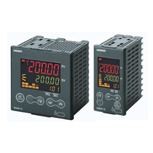
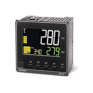
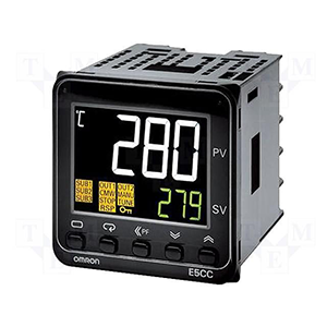
| Applicable models | E5AN/E5EN/E5CN/E5CN-U/E5AN-H/E5EN-H/E5CN-H/E5GN |
| USB interface standard | Conforms to USB Specification 1.1. |
| DTE speed | 38400 bps |
| Connector specifications |
Computer: USB (type A plug) Temperature Controller: Setup Tool port (on bottom of Controller) |
| Power supply | Bus power (Supplied from USB host controller.) |
| Power supply voltage | 5 VDC |
| Current consumption | 70 mA |
| Ambient operating temperature | 0 to 55°C (with no condensation or icing) |
| Ambient operating humidity | 10% to 80% |
| Storage temperature | - 20 to 60°C (with no condensation or icing) |
| Storage humidity | 10% to 80% |
| Altitude | 2,000 m max. |
| Weight | Approx. 100 g |
| Transmission line connection method |
RS-485: Multipoint RS-232C: Point-to-point |
|---|---|
| Communications | RS-485 (two-wire, half duplex), RS-232C |
| Synchronization method | Start-stop synchronization |
| Protocol | CompoWay/F, SYSWAY, or Modbus |
| Baud rate | 1200, 2400, 4800, 9600, 19200, 38400, or 57600 bps |
| Transmission code | ASCII |
| Data bit length * | 7 or 8 bits |
| Stop bit length * | 1 or 2 bits |
| Error detection |
Vertical parity (none, even, odd) Frame check sequence (FCS) with SYSWAY Block check character (BCC) with CompoWay/F or CRC-16 Modbus |
| Flow control | None |
| Interface | RS-485, RS-232C |
| Retry function | None |
| Communications buffer | 217 bytes |
| Communications response wait time |
0 to 99 ms Default: 20 ms |
| Dielectric strength | 1,000 VAC for 1 min |
|---|---|
| Vibration resistance | 50 Hz, 98 m/s2 |
| Weight | E54-CT1: Approx. 11.5 g, E54-CT3: Approx. 50 g |
| Accessories (E54-CT3 only) |
Armatures (2) Plugs (2) |
| CT input (for heater current detection) | Models with detection for single-phase heaters: One input |
|---|---|
| Maximum heater current | 50 A AC |
| Input current indication accuracy | ±5% FS ±1 digit max. |
| Heater burnout alarm setting range *1 |
0.1 to 49.9 A (in units of 0.1 A) Minimum detection ON time: 100 ms |
| SSR failure alarm setting range *2 |
0.1 to 49.9 A (in units of 0.1 A) Minimum detection OFF time: 100 ms |
| Heater overcurrent alarm setting range *3 |
0.1 to 49.9 A (in units of 0.1 A) Minimum detection ON time: 100 ms |
Order the Waterproof Packing separately if it becomes lost or damaged.
The Waterproof Packing can be used to achieve an IP66 degree of protection.
(Deterioration, shrinking, or hardening of the waterproof packing may occur depending on the operating environment. Therefore, periodic replacement is recommended to ensure the level of waterproofing specified in IP66. The time for periodic replacement depends on the operating environment. Be sure to confirm this point at your site. Consider one year a rough standard. OMRON shall not be liable for the level of water resistance if the customer does not perform periodic replacement.)
The Waterproof Packing does not need to be attached if a waterproof structure is not required.
Maximum continuous heater current: 50 A (50/60 Hz)
Number of windings: 400±2
Winding resistance: 18±2 Ω
Maximum continuous heater current: 120 A (50/60 Hz)
(Maximum continuous heater current for the Temperature Controller is 50 A.)
Number of windings: 400±2
Winding resistance: 8±0.8 Ω