The new cutting oil resistant Robust type is added
last update: April 2, 2018
The new cutting oil resistant Robust type is added
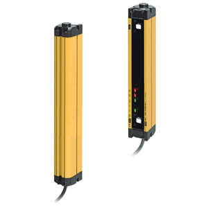
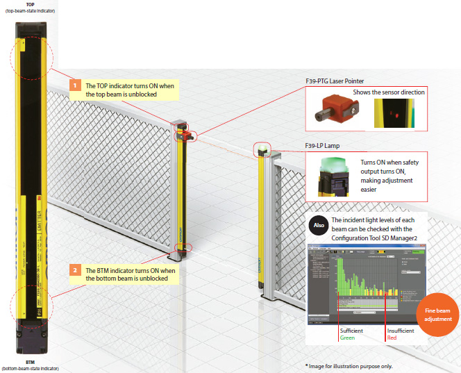
Simply watch for the top and bottom indicators to illuminate when adjustment is completed.
The optional laser pointer and lamp can be used to reduce the time required to set up the light curtain.
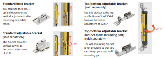
Four types of mounting brackets provide vertical or vertical and horizontal adjustment even after mounting, making beam adjustment easier.
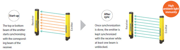
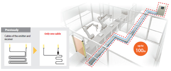
Optical synchronization eliminates the need of wiring for synchronization between the emitter and receiver.
The resulting flexible wiring reduces disconnection risk and avoids noise sources.
No torque-control required:
the Smartclick connectors connect cables with just a 1/8th turn of the M12 waterproof connector.
* Smartclick is a registered trademark of OMRON Corporation.
Simple wiring makes installation faster.
Fewer cables reduce disconnection risk and noise trouble.
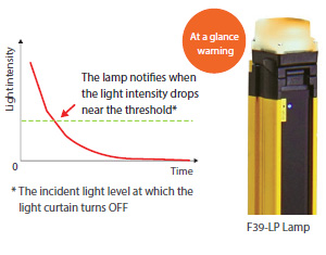
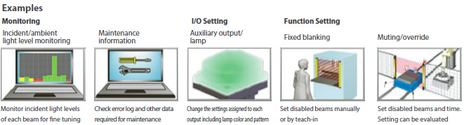
The lamp notifies when the incident light level drops due to dirt, which mp hich prevents sudden stops.
The error logs stored in the F3SG-RA can be downloaded to a PC that is connected with the F3SG-RA using the dedicated interface unit. The Configuration Tool SD Manager2 can be used to analyze errors to identify causes and solutions. The data on light intensity, power-ON time, and switching frequency can also be collected regularly for predictive maintenance.
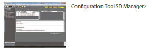
The SD Manager2 can be used to check the status of the safety light curtain wirelessly after pairing the safety light curtain with PC via Bluetooth®, which reduces maintenance time.
Wireless connectivity
- Monitoring during operation
- No possibility of blocking beams
- No work required after completing checks
- Monitoring from anywhere
- Serial number to choose the right safety light curtain from many installed on lines
The F3SG-RA is designed to be used in a variety of environments around the world, conforming to international standards.
Omron enhanced the global production bases and local services in Japan, China, United States, and Europe to deliver Omron products quickly and reliably. Our sales network of approximately 150 offices in 40 countries and regions supports our customers.
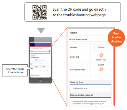
You can find causes and solutions of errors that occur during operation on the troubleshooting webpage in eight languages. Operators across the world can check the error details in their local languages, which will help them minimize time to troubleshoot.
* English, Chinese, Italian, Korean, French, German, Spanish, and Japanese
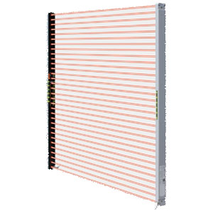
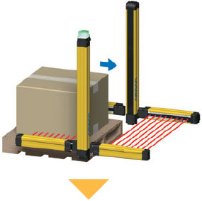
The F3SG-RA provides the advanced Muting function that disables beams which detect the presence of a workpiece or the position of a machine or robot.
Workpieces can go in and out of a danger zone without stopping the machine.
[Conventional Muting] Muting secured safety, but the set-up was time consuming.
The smart muting actuator extends the functions of the F3SG-R in applications where a workpiece is vibrating forward and backward This prevents unexpected machine downtime and significantly reduces adjustment time.
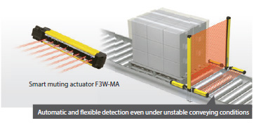
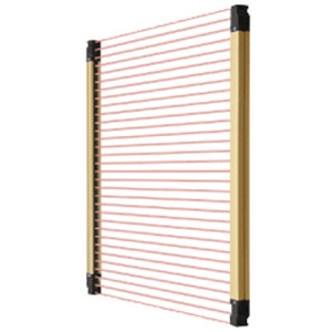
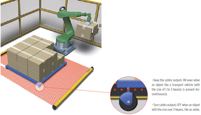
When workpieces with various heights are conveyed on the same line, the dynamic muting function automatically sets the appropriate beams, based on the height of the object.
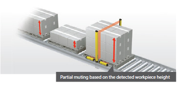
* Partial muting: A function that allows specified beams (e.g., beams blocked by a workpiece) to be disabled, keeping others active, even during muting.
The Configuration Tool SD Manager2 visualizes the installation positions and settings by logging the muting sensor operating conditions of the F3SG-R. It helps ensure reliable, first-time-right configuration.
The SD Manager2 helps you to make and change settings.
The Configuration Tool SD Manager2 is available to download from
Omron website:
http://www.ia.omron.com/f3sg-r_tool
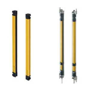
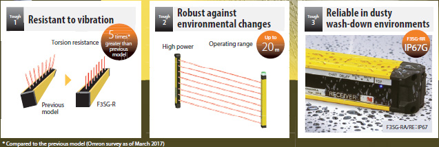
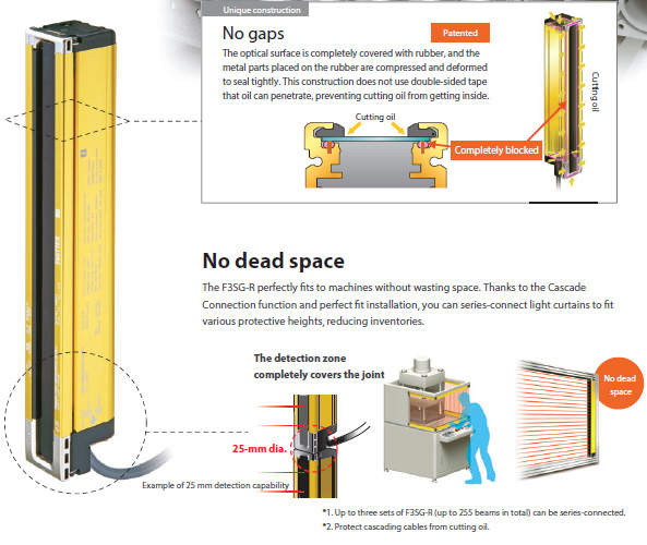
The F3SG-RR has the ability to protect from cutting oil (IP67G) for four times longer than the previous model.
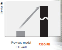
* Compared to the previous model (Omron survey as of March 2017)
The Easy type inherits the robust but slim housing and basic safety features of the Advanced type. Simple ON/OFF detection reduces errors, preventing productivity from dropping.
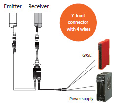
Only four wires are required for the minimum configuration, which is as simple as wiring a photoelectric sensor. Simple connection with a safety controller makes it easy to build a safety circuit.
The Easy type that allows the distance between the light curtain and hazard source to be reduced is ideal for the use in a small machine.
* Omron survey as of March 2017
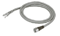
Commercially available M12 connector cables can be used as extension cables to build a safety circuit.
last update: April 2, 2018
last update: April 3, 2017
F3SG-4RA[][][][]-14 F3SG-2RA[][][][]-14 |
F3SG-4RA[][][][]-30 F3SG-2RA[][][][]-30 |
|||
---|---|---|---|---|
Type of ESPE (IEC 61496-1) |
Type 4 | F3SG-4RA[][][][]-14/-30 | ||
Type 2 | F3SG-2RA[][][][]-14/-30 | |||
Perform- ance |
Object Resolution (Detection Capability) |
Opaque objects | ||
14-mm dia. | 30-mm dia. | |||
Beam Gap | 10 mm | 20 mm | ||
Number of Beams | 15 to 207 | 8 to 124 | ||
Lens Size | 5.2 × 3.4 (W × H) mm | 7-mm dia. | ||
Protective Height | 160 to 2080 mm (6.3 to 81.9 inch) | 190 to 2510 mm (7.3 to 98.7 inch) | ||
Operating Range |
Long | 0.3 to 10.0 m (1 to 32 ft.) | 0.3 to 20.0 m (1 to 65 ft.) | |
Short | 0.3 to 3.0 m (1 to 10 ft.) | 0.3 to 7.0 m (1 to 23 ft.) | ||
Response Time |
ON to OFF |
Normal mode: 8 to 18 ms max. *1 Slow mode: 16 to 36 ms max. *1 *2 |
||
OFF to ON | 40 to 90 ms max. *1 | |||
*1 Response time when used in one segment system or in cascaded connection. Refer to "List of Models/Response Time/Current Consumption/Weight". *2 Selectable by Configuration Tool. |
||||
Effective Aperture Angle (EAA) (IEC 61496-2) |
Type 4 | ±2.5° max., emitter and receiver at operating range of 3 m or greater | ||
Type 2 | ±5.0° max., emitter and receiver at operating range of 3 m or greater | |||
Light Source | Infrared LEDs, Wavelength: 870 nm | |||
Startup Waiting Time | 2 s max. | |||
Elec- trical |
Power Supply Voltage (Vs) | SELV/PELV 24 VDC±20% (ripple p-p 10% max.) | ||
Current Consumption | Refer to "List of Models/Response Time/Current Consumption/Weight". | |||
Safety Outputs (OSSD) |
Two PNP or NPN transistor outputs (PNP or NPN is selectable by DIP Switch.) Load current of 300 mA max., Residual voltage of 2 V max. (except for voltage drop due to cable extension), Capacitive load of 1 μF max., Inductive load of 2.2 H max. *1 Leakage current of 1 mA max. (PNP), 2 mA max. (NPN) *2 *1 The load inductance is the maximum value when the safety output frequently repeats ON and OFF. When you use the safety output at 4 Hz or less, the usable load inductance becomes larger. *2 These values must be taken into consideration when connecting elements including a capacitive load such as a capacitor. |
|||
Auxiliary Output |
One PNP or NPN transistor output (PNP or NPN is selectable by DIP Switch.) Load current of 100 mA max., Residual voltage of 2 V max . |
|||
Output Operation Mode |
Safety Output |
Light-ON (Safety output is enabled when the receiver receives an emitting signal.) |
||
Auxiliary Output |
Safety output (Inverted signal output:Enable) (default) (Cofigurable by Configuration Tool) |
|||
Input Voltage |
ON Voltage |
TEST: 24 V Active: 9 V to Vs (sink current 3 mA max.) * 0 V Active: 0 to 3 V (source current 3 mA max.) MUTE A/B: PNP: Vs to Vs-3 V (sink current 3 mA max.) * NPN: 0 to 3 V (source current 3 mA max.) RESET: PNP: Vs to Vs-3 V (sink current 5 mA max.) * NPN: 0 to 3 V (source current 5 mA max.) |
||
OFF Voltage |
TEST: 24 V Active: 0 to 1.5 V or open 0 V Active: 9 V to Vs or open MUTE A/B, RESET: PNP: 0 to 1/2 Vs, or open * NPN: 1/2 Vs to Vs, or open * |
|||
* The Vs indicates a supply voltage value in your environment. | ||||
Overvoltage Category (IEC 60664-1) |
II | |||
Indicators | Refer to "Indicator". | |||
Protective Circuit | Output short protection, Power supply reverse polarity protection | |||
Insulation Resistance | 20 MΩ or higher (500 VDC megger) | |||
Dielectric Strength | 1,000 VAC, 50/60 Hz (1 min) | |||
Func- tional |
Mutual Interference Prevention (Scan Code) |
This function prevents mutual interference in up to two F3SG-RA systems. |
||
Cascade Connection |
Number of cascaded segments: 3 max. Total number of beams: 255 max. Cable lengths between sensors: 10 m max. |
|||
Test Function |
Self-test (at power-on, and during operation) External test (light emission stop function by test input) |
|||
Safety-Related Functions |
Interlock External device monitoring (EDM) Pre-reset Fixed blanking/Floating blanking Reduced resolution Muting/Override Scan code selection PNP/NPN selection Response time adjustment |
|||
Environ- mental |
Ambient Temperature |
Operating | -10 to 55°C (14 to 131°F) (non-icing) | |
Storage | -25 to 70°C (-13 to 158°F) | |||
Ambient Humidity |
Operating | 35% to 85% (non-condensing) | ||
Storage | 35% to 95% | |||
Ambient Illuminance |
Incandescent lamp: 3,000 Ix max. on receiver surface Sunlight: 10,000 Ix max. on receiver surface |
|||
Degree of Protection (IEC 60529) |
IP65 and IP67 | |||
Vibration Resistance (IEC 61496-1) |
10 to 55 Hz, Multiple amplitude of 0.7 mm, 20 sweeps for all 3 axes | |||
Shock Resistance (IEC 61496-1) | 100 m/s2, 1000 shocks for all 3 axes | |||
Pollution Degree (IEC 60664-1) | Pollution Degree 3 | |||
Connec- tions |
Power cable |
Type of Connection |
M12 connectors: 5-pin emitter and 8-pin receiver, IP67 rated when mated, Cables prewired to the sensors |
|
Number of Wires | Emitter: 5, Receiver: 8 | |||
Cable Length | 0.3 m | |||
Cable Diameter | 6 mm | |||
Minimum Bending Radius |
R5 mm | |||
Cascading cable |
Type of Connection |
M12 connectors: 5-pin emitter and 8-pin receiver, IP67 rated when mated |
||
Number of Wires | Emitter: 5, Receiver: 8 | |||
Cable Length | 0.2 m | |||
Cable Diameter | 6 mm | |||
Minimum Bending Radius |
R5 mm | |||
Extension cable - Single- ended cable - Double- ended cable |
Type of Connection |
M12 connectors: 5-pin emitter and 8-pin receiver, IP67 rated when mated |
||
Number of Wires | Emitter: 5, Receiver: 8 | |||
Cable Length | Refer to Lineup. | |||
Cable Diameter | 6.6 mm | |||
Minimum Bending Radius |
R36 mm | |||
Extension of Power Cable | 100 m max. | |||
Material | Material |
Housing: Aluminum Cap: PBT Front window: PMMA Cable: Oil resistant PVC Mounting Bracket: ZDC2 FE plate: SUS |
||
Weight (packaged) | Refer to "List of Models/Response Time/Current Consumption/Weight". | |||
Included Accessories |
Safety Precautions, Quick Installation Manual, Standard Fixed Bracket*, Troubleshooting Guide Sticker, Warning Zone Label * The quantity of Standard Fixed Brackets included varies depending on the protective height. [F3SG-[]RA[][][][]-14] - Protective height of 0160 to 1200: 2 sets - Protective height of 1280 to 2080: 3 sets [F3SG-[]RA[][][][]-30] - Protective height of 0190 to 1230: 2 sets - Protective height of 1310 to 2270: 3 sets - Protective height of 2350 to 2510: 4 sets |
|||
Con- formity |
Conforming standards | Refer to "Legislation and Standards". | ||
Type of ESPE (IEC 61496-1) | Type 4 | |||
Performance Level (PL)/ Safety category |
Type 4 | PL e/Category 4 (EN ISO 13849-1:2008) | ||
Type 2 | PL c/Category 2 (EN ISO 13849-1:2008) | |||
PFHd | 1.1 × 10⁻⁸(IEC 61508) | |||
Proof test interval TM | Every 20 years (IEC 61508) | |||
SFF | 99% (IEC 61508) | |||
HFT | 1 (IEC 61508) | |||
Classification | Type B (IEC 61508-2) |
F3SG-4RA[][][][]-25-01TS | |||
---|---|---|---|
Type of ESPE (IEC 61496-1) |
Type 4 | F3SG-4RA[][][][]-25-01TS | |
Perform- ance |
Object Resolution (Detection Capability) |
Opaque objects | |
25-mm dia. | |||
Beam Gap | 20 mm | ||
Number of Beams | 8 to 96 | ||
Lens Size | 6.0×5.0 (W×H) mm | ||
Protective Height | 185 to 1945 mm (7.3 to 76.6 inch) | ||
Operating Range |
Long | 0.3 to 17.0 m (1 to 56 ft.) | |
Short | 0.3 to 5.0 m (1 to 16 ft.) | ||
Response Time |
ON to OFF | 8 to 13 ms *1 | |
OFF to ON | 40 to 65ms *1 | ||
*1 Response time when used in one segment system or in cascaded connection. Refer to "List of Models/Response Time/Current Consumption/Weight". |
|||
Effective Aperture Angle (EAA) (IEC 61496-2) |
Type 4 | ±2.5° max., emitter and receiver at operating range of 3 m or greater | |
Light Source | Infrared LEDs, Wavelength: 870 nm | ||
Startup Waiting Time | 2 s max. | ||
Elec- trical |
Power Supply Voltage (Vs) | SELV/PELV 24 VDC±20% (ripple p-p 10% max.) | |
Current Consumption | Refer to "List of Models/Response Time/Current Consumption/Weight". | ||
Safety Outputs (OSSD) | Two PNP or NPN transistor outputs (PNP or NPN is selectable by DIP Switch.) | ||
Load current of 300 mA max., Residual voltage of 2 V max. (except for voltage drop due to cable extension), Capacitive load of 1 μF max., Inductive load of 2.2 H max. *1 Leakage current of 1 mA max. (PNP), 2 mA max. (NPN) *2 *1.*The load inductance is the maximum value when the safety output frequently repeats ON and OFF. When you use the safety output at 4 Hz or less, the usable load inductance becomes larger. *2.*These values must be taken into consideration when connecting elements including a capacitive load such as a capacitor. |
|||
Auxiliary Output |
One PNP or NPN transistor output (Safety Output and homopolarity) Load current of 100 mA max., Residual voltage of 2 V max . |
||
Output Operation Mode |
Safety Output | Light-ON (Safety output is enabled when the receiver receives an emitting signal.) | |
Auxiliary Output | Reverse output of safety output | ||
Input Voltage |
External device monitoring input (Lockout reset input) |
PNP ON voltage: Vs-3 V to Vs (short circuit current: approx. 6.5 mA) * OFF voltage: 0 V to 1/2 Vs, or open (short circuit current: approx. 8.0 mA) * NPN ON voltage: 0 V to 3 V (short circuit current: approx. 8.0 mA) * OFF voltage: 1/2 Vs to Vs, or open (short circuit current: approx. 6.5 mA) * |
|
Test input |
TEST: 24 V inactive setting ON voltage: 0 V to 1.5 V or open (short circuit current: approx. 2.0 mA) OFF voltage: 9 V to Vs (short circuit current: approx. 2.5 mA) * 0 V inactive setting ON voltage: 9 V to Vs or open (short circuit current: approx. 2.5 mA) OFF voltage: 0 V to 3 V (short circuit current: approx. 2.0 mA) |
||
* The Vs indicates a supply voltage value in your environment. | |||
Overvoltage Category (IEC 60664-1) |
II | ||
Indicators | Refer to "Indicator". | ||
Protective Circuit | Output short protection, Power supply reverse polarity protection | ||
Insulation Resistance | 20 MΩ or higher (500 VDC megger) | ||
Dielectric Strength | 1,000 VAC, 50/60 Hz (1 min) | ||
Func- tional |
Mutual Interference Prevention (Scan Code) |
This function prevents mutual interference in up to two F3SG-RA systems. | |
Cascade Connection |
Number of cascaded segments: 3 max. Total number of beams: 255 max. Cable length between sensors: 10 m max. |
||
Test Function |
Self-test (at power-on, and during operation) External test (light emission stop function by test input) |
||
Safety-Related Functions |
External device monitoring (EDM) Scan code selection PNP/NPN selection |
||
Environ- mental |
Ambient Temperature |
Operating | -10 to 55°C (14 to 131°F) (non-icing) |
Storage | -25 to 70°C (-13 to 158°F) | ||
Ambient Humidity |
Operating | 35% to 85% (non-condensing) | |
Storage | 35% to 95% | ||
Ambient Illuminance |
Incandescent lamp: 3,000 Ix max. on receiver surface Sunlight: 10,000 Ix max. on receiver surface |
||
Degree of Protection (IEC 60529) |
IP65 and IP67 | ||
Vibration Resistance (IEC 61496-1) |
10 to 55 Hz, Multiple amplitude of 0.7 mm, 20 sweeps for all 3 axes | ||
Shock Resistance (IEC 61496-1) |
100 m/s2, 1000 shocks for all 3 axes | ||
Pollution Degree (IEC 60664-1) |
Pollution Degree 3 | ||
Connec- tions |
Power cable |
Type of Connection |
M12 connectors: 8-pin emitter and receiver, IP67 rated when mated, Cables prewired to the sensors |
Number of Wires | On emitter: 5-wire, On receiver: 8-wire | ||
Cable Length | 0.3 m | ||
Cable Diameter | 6 mm | ||
Minimum Bending Radius |
R5 mm | ||
Cascading cable |
Type of Connection |
M12 connectors: 8-pin emitter and receiver, IP67 rated when mated | |
Number of Wires | On emitter: 5-wire, On receiver: 8-wire | ||
Cable Length | 0.2 m | ||
Cable Diameter | 6 mm | ||
Minimum Bending Radius |
R5 mm | ||
Extension cable - Single- ended cable - Double- ended cable |
Type of Connection |
M12 connectors: 8-pin emitter and receiver, IP67 rated when mated | |
Number of Wires | On emitter and receiver: 8-wire | ||
Cable Length | Refer to Lineup. | ||
Cable Diameter | 6.6 mm | ||
Minimum Bending Radius |
R36 mm | ||
Extension of Power Cable | 100 m max.(Emitter/Receiver) | ||
Material | Material |
Housing: Aluminum Cap: PBT Front window: PMMA Cable: Oil resistant PVC FE plate: SUS |
|
Weight (packaged) | Refer to "List of Models/Response Time/Current Consumption/Weight". | ||
Included Accessories | Safety Precautions, Quick Installation Manual, Troubleshooting Guide Sticker, | ||
Con- formity |
Conforming standards | Refer to "Legislation and Standards". | |
Performance Level (PL)/ Safety category |
Type 4 | ||
PFHd | 1.1 × 10⁻⁸ (IEC 61508) | ||
Proof test interval TM | Every 20 years (IEC 61508) | ||
SFF | 99% (IEC 61508) | ||
HFT | 1 (IEC 61508) | ||
Classification | Type B (IEC 61508-2) |
Communication System | Bluetooth Version 3.0 |
---|---|
Communication Profile | SPP (Serial Port Profile) |
Transmission Distance | Approx. 10 m max. (Output power: Class 2) * |
* It depends on use environment conditions.
Model |
Num- ber of Beams |
Pro- tective Height [mm] |
Response Time [ms] |
Current Consumption [mA] |
Weight [kg] *2 |
||||
---|---|---|---|---|---|---|---|---|---|
ON → OFF *1 |
OFF (Syn- chro- nized) → ON |
OFF (Not syn- chro- nized) → ON |
Emitter |
Re- ceiver |
|||||
F3SG-4RA0160-14 | F3SG-2RA0160-14 | 15 | 160 | 8 | 40 | 140 | 40 | 75 | 1.8 |
F3SG-4RA0240-14 | F3SG-2RA0240-14 | 23 | 240 | 8 | 40 | 140 | 45 | 75 | 2.0 |
F3SG-4RA0320-14 | F3SG-2RA0320-14 | 31 | 320 | 8 | 40 | 140 | 55 | 75 | 2.2 |
F3SG-4RA0400-14 | F3SG-2RA0400-14 | 39 | 400 | 8 | 40 | 140 | 60 | 80 | 2.7 |
F3SG-4RA0480-14 | F3SG-2RA0480-14 | 47 | 480 | 13 | 65 | 165 | 50 | 80 | 2.9 |
F3SG-4RA0560-14 | F3SG-2RA0560-14 | 55 | 560 | 13 | 65 | 165 | 55 | 80 | 3.1 |
F3SG-4RA0640-14 | F3SG-2RA0640-14 | 63 | 640 | 13 | 65 | 165 | 60 | 85 | 3.3 |
F3SG-4RA0720-14 | F3SG-2RA0720-14 | 71 | 720 | 13 | 65 | 165 | 65 | 85 | 3.9 |
F3SG-4RA0800-14 | F3SG-2RA0800-14 | 79 | 800 | 13 | 65 | 165 | 65 | 90 | 4.1 |
F3SG-4RA0880-14 | F3SG-2RA0880-14 | 87 | 880 | 13 | 65 | 165 | 70 | 90 | 4.3 |
F3SG-4RA0960-14 | F3SG-2RA0960-14 | 95 | 960 | 13 | 65 | 165 | 75 | 90 | 4.5 |
F3SG-4RA1040-14 | F3SG-2RA1040-14 | 103 | 1040 | 13 | 65 | 165 | 80 | 95 | 4.7 |
F3SG-4RA1120-14 | F3SG-2RA1120-14 | 111 | 1120 | 13 | 65 | 165 | 85 | 95 | 4.8 |
F3SG-4RA1200-14 | F3SG-2RA1200-14 | 119 | 1200 | 13 | 65 | 165 | 90 | 100 | 5.0 |
F3SG-4RA1280-14 | F3SG-2RA1280-14 | 127 | 1280 | 13 | 65 | 165 | 95 | 100 | 5.2 |
F3SG-4RA1360-14 | F3SG-2RA1360-14 | 135 | 1360 | 13 | 65 | 165 | 95 | 105 | 5.6 |
F3SG-4RA1440-14 | F3SG-2RA1440-14 | 143 | 1440 | 18 | 90 | 190 | 85 | 105 | 5.8 |
F3SG-4RA1520-14 | F3SG-2RA1520-14 | 151 | 1520 | 18 | 90 | 190 | 90 | 105 | 6.0 |
F3SG-4RA1600-14 | F3SG-2RA1600-14 | 159 | 1600 | 18 | 90 | 190 | 90 | 110 | 6.6 |
F3SG-4RA1680-14 | F3SG-2RA1680-14 | 167 | 1680 | 18 | 90 | 190 | 95 | 110 | 6.8 |
F3SG-4RA1760-14 | F3SG-2RA1760-14 | 175 | 1760 | 18 | 90 | 190 | 100 | 115 | 7.0 |
F3SG-4RA1840-14 | F3SG-2RA1840-14 | 183 | 1840 | 18 | 90 | 190 | 100 | 115 | 7.2 |
F3SG-4RA1920-14 | F3SG-2RA1920-14 | 191 | 1920 | 18 | 90 | 190 | 105 | 120 | 7.3 |
F3SG-4RA2000-14 | F3SG-2RA2000-14 | 199 | 2000 | 18 | 90 | 190 | 105 | 120 | 7.5 |
F3SG-4RA2080-14 | F3SG-2RA2080-14 | 207 | 2080 | 18 | 90 | 190 | 110 | 125 | 8.1 |
*1 The response times are values when Scan Code is set at Code B. The response times for Code A are 1 ms shorter
than these values.
*2 The weight includes an emitter, a receiver and included brackets in a product package.
Model |
Num- ber of Beams |
Pro- tective Height [mm] |
Response Time [ms] |
Current Consumption [mA] |
Weight [kg] *2 |
||||
---|---|---|---|---|---|---|---|---|---|
ON → OFF *1 |
OFF (Syn- chro- nized) → ON |
OFF (Not syn- chro- nized) → ON |
Emitter |
Re-
ceiver |
|||||
F3SG-4RA0190-30 | F3SG-2RA0190-30 | 8 | 190 | 8 | 40 | 140 | 35 | 75 | 1.8 |
F3SG-4RA0270-30 | F3SG-2RA0270-30 | 12 | 270 | 8 | 40 | 140 | 35 | 75 | 2.0 |
F3SG-4RA0350-30 | F3SG-2RA0350-30 | 16 | 350 | 8 | 40 | 140 | 40 | 75 | 2.2 |
F3SG-4RA0430-30 | F3SG-2RA0430-30 | 20 | 430 | 8 | 40 | 140 | 45 | 75 | 2.7 |
F3SG-4RA0510-30 | F3SG-2RA0510-30 | 24 | 510 | 8 | 40 | 140 | 50 | 75 | 2.9 |
F3SG-4RA0590-30 | F3SG-2RA0590-30 | 28 | 590 | 8 | 40 | 140 | 50 | 75 | 3.1 |
F3SG-4RA0670-30 | F3SG-2RA0670-30 | 32 | 670 | 8 | 40 | 140 | 55 | 75 | 3.3 |
F3SG-4RA0750-30 | F3SG-2RA0750-30 | 36 | 750 | 8 | 40 | 140 | 60 | 80 | 3.9 |
F3SG-4RA0830-30 | F3SG-2RA0830-30 | 40 | 830 | 8 | 40 | 140 | 65 | 80 | 4.0 |
F3SG-4RA0910-30 | F3SG-2RA0910-30 | 44 | 910 | 13 | 65 | 165 | 50 | 80 | 4.2 |
F3SG-4RA0990-30 | F3SG-2RA0990-30 | 48 | 990 | 13 | 65 | 165 | 50 | 80 | 4.4 |
F3SG-4RA1070-30 | F3SG-2RA1070-30 | 52 | 1070 | 13 | 65 | 165 | 55 | 80 | 4.6 |
F3SG-4RA1150-30 | F3SG-2RA1150-30 | 56 | 1150 | 13 | 65 | 165 | 55 | 85 | 4.8 |
F3SG-4RA1230-30 | F3SG-2RA1230-30 | 60 | 1230 | 13 | 65 | 165 | 55 | 85 | 4.9 |
F3SG-4RA1310-30 | F3SG-2RA1310-30 | 64 | 1310 | 13 | 65 | 165 | 60 | 85 | 5.1 |
F3SG-4RA1390-30 | F3SG-2RA1390-30 | 68 | 1390 | 13 | 65 | 165 | 60 | 85 | 5.6 |
F3SG-4RA1470-30 | F3SG-2RA1470-30 | 72 | 1470 | 13 | 65 | 165 | 65 | 85 | 5.8 |
F3SG-4RA1550-30 | F3SG-2RA1550-30 | 76 | 1550 | 13 | 65 | 165 | 65 | 90 | 6.0 |
F3SG-4RA1630-30 | F3SG-2RA1630-30 | 80 | 1630 | 13 | 65 | 165 | 70 | 90 | 6.5 |
F3SG-4RA1710-30 | F3SG-2RA1710-30 | 84 | 1710 | 13 | 65 | 165 | 70 | 90 | 6.7 |
F3SG-4RA1790-30 | F3SG-2RA1790-30 | 88 | 1790 | 13 | 65 | 165 | 70 | 90 | 6.9 |
F3SG-4RA1870-30 | F3SG-2RA1870-30 | 92 | 1870 | 13 | 65 | 165 | 75 | 90 | 7.1 |
F3SG-4RA1950-30 | F3SG-2RA1950-30 | 96 | 1950 | 13 | 65 | 165 | 75 | 95 | 7.3 |
F3SG-4RA2030-30 | F3SG-2RA2030-30 | 100 | 2030 | 13 | 65 | 165 | 80 | 95 | 7.4 |
F3SG-4RA2110-30 | F3SG-2RA2110-30 | 104 | 2110 | 13 | 65 | 165 | 80 | 95 | 8.0 |
F3SG-4RA2190-30 | F3SG-2RA2190-30 | 108 | 2190 | 13 | 65 | 165 | 85 | 95 | 8.2 |
F3SG-4RA2270-30 | F3SG-2RA2270-30 | 112 | 2270 | 13 | 65 | 165 | 85 | 100 | 8.4 |
F3SG-4RA2350-30 | F3SG-2RA2350-30 | 116 | 2350 | 13 | 65 | 165 | 85 | 100 | 8.8 |
F3SG-4RA2430-30 | F3SG-2RA2430-30 | 120 | 2430 | 13 | 65 | 165 | 90 | 100 | 8.9 |
F3SG-4RA2510-30 | F3SG-2RA2510-30 | 124 | 2510 | 13 | 65 | 165 | 90 | 100 | 9.1 |
*1 The response times are values when Scan Code is set at Code B. The response times for Code A are 1 ms shorter
than these values.
The maximum speed of movement of a test rod up to which the detection capability is maintained is 2.0 m/s.
*2 .The weight includes an emitter, a receiver and included brackets in a product package.
Model |
Number of Beams |
Pro- tective Height [mm] |
Response Time [ms] |
Current Consumption [mA] |
Weight [kg] *3 |
|||
---|---|---|---|---|---|---|---|---|
ON → OFF *1 |
OFF (Syn- chronized) → ON |
OFF (Not synchronized) → ON |
Emitter | Receiver | ||||
F3SG-4RA0185-25 | 8 | 185 | 8 | 40 | 140 | 35 | 75 | 1.2 |
F3SG-4RA0265-25 | 12 | 265 | 8 | 40 | 140 | 35 | 75 | 1.4 |
F3SG-4RA0345-25 | 16 | 345 | 8 | 40 | 140 | 40 | 75 | 1.6 |
F3SG-4RA0425-25 | 20 | 425 | 8 | 40 | 140 | 45 | 75 | 2.1 |
F3SG-4RA0505-25 | 24 | 505 | 8 | 40 | 140 | 50 | 75 | 2.3 |
F3SG-4RA0585-25 | 28 | 585 | 8 | 40 | 140 | 50 | 75 | 2.4 |
F3SG-4RA0665-25 | 32 | 665 | 8 | 40 | 140 | 55 | 75 | 2.6 |
F3SG-4RA0745-25 | 36 | 745 | 8 | 40 | 140 | 60 | 80 | 3.1 |
F3SG-4RA0825-25 | 40 | 825 | 8 | 40 | 140 | 65 | 80 | 3.2 |
F3SG-4RA0905-25 | 44 | 905 | 13 | 65 | 165 | 50 | 80 | 3.4 |
F3SG-4RA0985-25 | 48 | 985 | 13 | 65 | 165 | 50 | 80 | 3.6 |
F3SG-4RA1065-25 | 52 | 1065 | 13 | 65 | 165 | 55 | 80 | 3.8 |
F3SG-4RA1145-25 | 56 | 1145 | 13 | 65 | 165 | 55 | 85 | 4.5 |
F3SG-4RA1225-25 | 60 | 1225 | 13 | 65 | 165 | 55 | 85 | 4.6 |
F3SG-4RA1305-25 | 64 | 1305 | 13 | 65 | 165 | 60 | 85 | 4.8 |
F3SG-4RA1385-25 | 68 | 1385 | 13 | 65 | 165 | 60 | 85 | 5.1 |
F3SG-4RA1465-25 | 72 | 1465 | 13 | 65 | 165 | 65 | 85 | 5.3 |
F3SG-4RA1545-25 | 76 | 1545 | 13 | 65 | 165 | 65 | 90 | 5.4 |
F3SG-4RA1625-25 | 80 | 1625 | 13 | 65 | 165 | 70 | 90 | 6.0 |
F3SG-4RA1705-25 | 84 | 1705 | 13 | 65 | 165 | 70 | 90 | 6.2 |
F3SG-4RA1785-25 | 88 | 1785 | 13 | 65 | 165 | 70 | 90 | 6.4 |
F3SG-4RA1865-25 | 92 | 1865 | 13 | 65 | 165 | 75 | 90 | 6.6 |
F3SG-4RA1945-25 | 96 | 1945 | 13 | 65 | 165 | 75 | 95 | 6.7 |
*1 The response times are values when Scan Code is set at Code B. The response times for Code A are 1 ms shorter
than these values.
*2 The weight includes an emitter and a receiver in a product package.
1. The F3SG-R does not receive type approval provided by Article 44-2 of the Industrial Safety and Health Act of Japan. When using the F3SG-R in Japan as a "safety system for pressing or shearing machines" prescribed in Article 42 of that law, the machine control system must receive type approval.
2. The F3SG-R is electro-sensitive protective equipment (ESPE) in accordance with European Union (EU) Machinery Directive Index Annex V, Item 2.
OMRON declares that the F3SG-R is in conformity with the requirements of the following EC Directives: Machinery Directive 2006/42/EC EMC Directive 2014/30/EU
(1) European standards EN61496-1 (Type 4 and Type 2 ESPE), EN 61496-2 (Type 4 and Type 2 AOPD), EN61508-1 through -4 (SIL 3 for Type 4 and SIL 1 for Type 2), EN ISO 13849-1:2008 (PL e, Category 4 for Type 4 and PL c, Category 2 for Type 2)
(2) International standards IEC61496-1 (Type 4 and Type 2 ESPE), IEC61496-2 (Type 4 and Type 2 AOPD), IEC61508-1 through -4 (SIL 3 for Type 4 and SIL 1 for Type 2), ISO 13849-1:2006 (PL e, Category 4 for Type 4 and PL c, Category 2 for Type 2)
(3) JIS standards JIS B 9704-1 (Type 4 and Type 2 ESPE), JIS B 9704-2 (Type 4 and Type 2 AOPD)
(4) North American standards UL61496-1(Type 4 and Type 2 ESPE), UL61496-2(Type 4 and Type 2 AOPD), UL508, UL1998, CAN/CSA C22.2 No.14, CAN/CSA C22.2 No.0.8
(5) Chinese standards * GB4584 (Specification of active opto-electronic protective devices for presses)
(1) TÜV SÜD
(2) UL
(3) China National Casting and Forging Machines Quality Supervision and Inspection Center *
The F3SG-R is designed according to the standards listed below. To make sure that the final system complies with
the following standards and regulations, you are asked to design and use it in accordance with all other related
standards, laws, and regulations. If you have any questions, consult with specialized organizations such as the body
responsible for prescribing and/or enforcing machinery safety regulations in the location where the equipment is to
be used.
* The F3SG-4RA[][][][]-25-01TS does not conform.
Name of Indicator | Color | Illuminated | Blinking | |
---|---|---|---|---|
Test | TEST | Green | - | External Test is being performed |
Operating range | LONG | Green | Long range mode is selected |
Lockout state due to DIP Switch setting error or Operating range selection setting error |
Power | POWER | Green | Power is ON. | Error due to noise |
Lockout | LOCKOUT | Red | - | Lockout state due to error in emitter |
Name of Indicator | Color | Illuminated | Blinking | |
---|---|---|---|---|
Top-beam-state | TOP | Blue | The top beam is unblocked |
Muting/Override state, or Lockout state due to Cap error or Other sensor error |
PNP/NPN mode | NPN | Green | NPN mode is selected by DIP Switch | - |
Response time | SLOW | Green | Response Time Adjustment is enabled | - |
Sequence error | SEQ | Yellow | - |
Sequence error in Muting or Pre-reset mode |
Blanking | BLANK | Green |
Blanking, Warning Zone or Reduced Resolution is enabled |
Teach-in mode, or Blanking Monitoring error |
Configuration | CFG | Green | - |
Teach-in mode, zone measurement beng performed by Dynamic Muting, or Lockout state due to Parameter error or Cascading Configuration error |
Interlock | INT-LK | Yellow | Interlock state | Pre-reset mode |
External device monitoring |
EDM | Green | RESET input is in ON state | Lockout state due to EDM error |
Internal error | INTERNAL | Red | - |
Lockout state due to Internal error, or error due to abnormal power supply or noise |
Lockout | LOCKOUT | Red | - | Lockout state due to error in receiver |
Stable-state | STB | Green |
Incident light level is 170% or higher of ON-threshold |
Safety output is instantaneously turned OFF due to ambient light or vibration |
ON/OFF | ON/OFF | Green | Safety output is in ON state | - |
Red |
Safety output is in OFF state, or the sensor is in Setting state |
Lockout state due to Safety Output error, or error due to abnormal power supply or noise |
||
Communication | COM | Green |
Synchronization between emitter and receiver is maintained |
Lockout state due to Communication error, or error due to abnormal power supply or noise |
Bottom-beam- state |
BTM | Blue | The bottom beam is unblocked |
Muting/Override state, or Lockout state due to DIP Switch setting error |
Location |
Name of Indicator |
Color | Illuminated | Blinking |
---|---|---|---|---|
1 | TEST | Green | - | External Test is being performed |
2 | LONG | Green |
Long range mode is selected |
Lockout state due to DIP Switch setting error or Operating range selection setting error |
3 | POWER | Green | Power is ON. | Error due to noise |
4 | LOCKOUT | Red | - | Lockout state due to error in emitter |
Location |
Name of Indicator |
Color | Illuminated | Blinking |
---|---|---|---|---|
1 | TOP | Blue | The top beam is unblocked | Lockout state due to Cap error or Other sensor error |
2 | NPN | Green |
NPN mode is selected by DIP Switch |
- |
3 | CFG | Green | - | Lockout state due to Cascading Configuration error |
4 | EDM | Green | EDM input is in ON state * | Lockout state due to EDM error |
5 | INTERNAL | Red | - |
Lockout state due to Internal error, or error due to abnormal power supply or noise |
6 | LOCKOUT | Red | - | Lockout state due to error in receiver |
7 | STB | Green |
Incident light level is 170% or higher of ON-threshold |
Safety output is instantaneously turned OFF due to ambient light or vibration. |
8 | ON/OFF | Green | Safety output is in ON state | - |
Red | Safety output is in OFF state |
Lockout state due to Safety Output error, or error due to abnormal power supply or noise |
||
9 | COM | Green |
Synchronization between emitter and receiver is maintained |
Lockout state due to Communication error, or error due to abnormal power supply or noise |
10 | BTM | Blue | The bottom beam is unblocked | Lockout state due to DIP Switch setting error |
* The LED is illuminated when the EDM input is in ON state regardless of wiring with EDM used or unused.
Main unit | PC/AT compatible machine (computer that runs Microsoft Windows) |
---|---|
Operating system (OS) | Windows 7 (32-bit/64-bit), Windows 8 (32-bit/64-bit) |
Communication port | USB port ×1 |
Ambient temperature | Operating: -10 to 55°C, Storage: -30 to 70°C(non-icing and non-condensing) |
Ambient humidity | Operating: 35% to 85%, Storage: 35% to 95%(non-condensing) |
Item | F39-LP |
---|---|
Applicable Sensor | F3SG-[]RA Series Safety Light Curtain (Receiver) |
LED Light Color | Red/Green/Orange |
Power Supply Voltage | 24 VDC±20%, ripple p-p 10% max. (shares sensor's power supply) |
Current Consumption | 25 mA max. (shares sensor's power supply.) |
Ambient Temperature | Operating: -10 to 55°C, Storage: -25 to 70°C |
Ambient Humidity | Operating: 35% to 85%, Storage: 35% to 95% |
Vibration Resistance | 10 to 55 Hz, Multiple amplitude of 0.7 mm, 20 sweeps for all 3 axes |
Shock Resistance | 100 m/s2, 1000 shocks for all 3 axes |
Degree of Protection | IP65 and IP67 (When attached to F3SG) |
Type of Connection | Connectable to F3SG-RA's terminal connector |
Material | Lighting element: PC, Other body parts: PBT |
Weight | 45 g (when packaged) |
F3SG-4RE[][][][]-14 F3SG-2RE[][][][]-14 |
F3SG-4RE[][][][]-30 F3SG-2RE[][][][]-30 |
|||
---|---|---|---|---|
Perform- ance |
Type of ESPE (IEC 61496-1) |
Type 4 | F3SG-4RE[][][][][]14/30 | |
Type 2 | F3SG-2RE[][][][][]14/30 | |||
Object Resolution (Detection Capability) |
Opaque objects | |||
14-mm dia. | 30-mm dia. | |||
Beam Gap | 10 mm | 20 mm | ||
Number of Beams | 15 to 207 | 8 to 124 | ||
Lens Size | 5.2 × 3.4 (W × H) mm | 7-mm dia. | ||
Protective Height | 160 to 2080 mm (6.3 to 81.9 inch) | 190 to 2510 mm (7.3 to 98.7 inch) | ||
Operating Range |
Long | 0.3 to 10.0 m (1 to 32 ft.) | 0.3 to 20.0 m (1 to 65 ft.) | |
Short | 0.3 to 3.0 m (1 to 10 ft.) | 0.3 to 7.0 m (1 to 23 ft.) | ||
Response Time |
ON to OFF | 5 to 15 ms *1 | ||
OFF to ON | 25 to 75 ms *1 | |||
*1. Response time when used in one segment system or in cascaded connection Refer to "List of Models/Response Time/Current Consumption/Weight" |
||||
Effective Aperture Angle (EAA) (IEC 61496-2) |
Type 4 | ±2.5° max., emitter and receiver at operating range of 3 m or greater | ||
Type 2 | ±5.0° max., emitter and receiver at operating range of 3 m or greater | |||
Light Source | Infrared LEDs, Wavelength: 870 nm | |||
Startup Waiting Time | 2 s max. | |||
Elec- tricall |
Power Supply Voltage (Vs) | SELV/PELV 24 VDC±20% (ripple p-p 10% max.) | ||
Current Consumption | Refer to "List of Models/Response Time/Current Consumption/Weight". | |||
Safety Outputs (OSSD) |
F3SG-[]RE[][][][]P[][]: Two PNP transistor outputs F3SG-[]RE[][][][]N[][]: Two NPN transistor outputs |
|||
Load current of 300 mA max., Residual voltage of 2 V max. (except for voltage drop due to cable extension), Capacitive load of 1 μF max., Inductive load of 2.2 H max. *1 Leakage current of 1 mA max. (PNP), 2 mA max. (NPN) *2 *1.The load inductance is the maximum value when the safety output frequently repeats ON and OFF. When you use the safety output at 4 Hz or less, the usable load inductance becomes larger. *2. These values must be taken into consideration when connecting elements including a capacitive load such as a capacitor. |
||||
Output Operation Mode |
Safety Output |
Light-ON (Safety output is enabled when the receiver receives an emitting signal.) |
||
Input Voltage |
ON Voltage |
Operating Range Select Input: Long: 9 V to Vs (sink current 3 mA max.) * Short: 0 to 3 V (source current 3 mA max.) |
||
OFF Voltage | ||||
*The Vs indicates a supply voltage value in your environment. | ||||
Overvoltage Category (IEC60664-1) |
II | |||
Indicators | Refer to "LED Indicator Status". | |||
Protective Circuit | Output short protection, Power supply reverse polarity protection | |||
Insulation Resistance | 20 MΩ or higher (500 VDC megger) | |||
Dielectric Strength | 1,000 VAC, 50/60 Hz (1 min) | |||
Func- tional |
Test Function | Self-test (at power-on, and during operation) | ||
Environ- mental |
Ambient Temperature |
Operating | -10 to 55°C (14 to 131°F) (non-icing) | |
Storage | -25 to 70°C (-13 to 158°F) | |||
Ambient Humidity |
Operating | 35% to 85% (non-condensing) | ||
Storage | 35% to 95% | |||
Ambient Illuminance |
Incandescent lamp: 3,000 Ix max. on receiver surface Sunlight: 10,000 Ix max. on receiver surface |
|||
Degree of Protection (IEC 60529) |
IP65 and IP67 | |||
Vibration Resistance (IEC 61496-1) |
10 to 55 Hz, Multiple amplitude of 0.7 mm, 20 sweeps for all 3 axes | |||
Shock Resistance (IEC 61496-1) | 100 m/s2, 1000 shocks for all 3 axes | |||
Pollution Degree (IEC 60664-1) | Pollution Degree 3 | |||
Connec- tions |
Power cable |
Type of Connection |
M12 connectors: 4-pin, IP67 rated when mated,Cables prewired to the sensors |
|
Number of Wires | Emitter: 4, Receiver: 4 | |||
Cable Length | 0.3 m | |||
Cable Diameter | 6 mm | |||
Minimum Bending Radius |
R5 mm | |||
Extension cable - Single- ended cable - Double- ended cable |
Type of Connection |
Use the XS5[]-D42[] series cables. | ||
Number of Wires | ||||
Cable Length | ||||
Cable Diameter | ||||
Minimum Bending Radius |
||||
Extension of Power Cable | 100 m max. | |||
Material | Material |
Housing: Aluminum Cap: PBT Front window: PMMA Cable: Oil resistant PVC Mounting Bracket: ZDC2 FE plate: SUS |
||
Weight (packaged) | Refer to "List of Models/Response Time/Current Consumption/Weight". | |||
Included Accessories |
Safety Precautions, Quick Installation Manual, Standard Fixed Bracket*1, Troubleshooting Guide Sticker *1. The quantity of Standard Fixed Brackets included varies depending on the protective height. [F3SG-[]RE[][][][][]14] - Protective height of 0160 to 1200: 2 sets - Protective height of 1280 to 2080: 3 sets [F3SG-[]RE[][][][][]30] - Protective height of 0190 to 1230: 2 sets - Protective height of 1310 to 2270: 3 sets - Protective height of 2350 to 2510: 4 sets |
|||
Con- formity |
Conforming standards | Refer to "Legislation and Standards". | ||
Performance Level (PL)/ Safety category |
Type 4 | PL e/Category 4 (EN ISO 13849-1:2008) | ||
Type 2 | PL c/Category 2 (EN ISO 13849-1:2008) | |||
PFHd | 9.1 × 10⁻⁹ (IEC 61508) | |||
Proof test interval TM | Every 20 years (IEC 61508) | |||
SFF | 99% (IEC 61508) | |||
HFT | 1 (IEC 61508) | |||
Classification | Type B (IEC 61508-2) |
Model |
Number of Beams |
Protective Height [mm] |
Response Time [ms] |
Current Consumption [mA] |
Weight [kg] * |
|||
---|---|---|---|---|---|---|---|---|
ON → OFF |
OFF (Syn- chronized) → ON |
OFF (Not syn- chronized) → ON |
Emitter | Receiver | ||||
F3SG-[]RE0160[]14 | 15 | 160 | 5 | 25 | 125 | 45 | 50 | 1.7 |
F3SG-[]RE0240[]14 | 23 | 240 | 5 | 25 | 125 | 55 | 55 | 1.9 |
F3SG-[]RE0320[]14 | 31 | 320 | 7 | 35 | 135 | 55 | 55 | 2.1 |
F3SG-[]RE0400[]14 | 39 | 400 | 7 | 35 | 135 | 65 | 60 | 2.6 |
F3SG-[]RE0480[]14 | 47 | 480 | 7 | 35 | 135 | 70 | 60 | 2.8 |
F3SG-[]RE0560[]14 | 55 | 560 | 7 | 35 | 135 | 80 | 60 | 3.1 |
F3SG-[]RE0640[]14 | 63 | 640 | 7 | 35 | 135 | 85 | 65 | 3.3 |
F3SG-[]RE0720[]14 | 71 | 720 | 9 | 45 | 145 | 80 | 65 | 3.8 |
F3SG-[]RE0800[]14 | 79 | 800 | 9 | 45 | 145 | 85 | 70 | 4.0 |
F3SG-[]RE0880[]14 | 87 | 880 | 9 | 45 | 145 | 90 | 70 | 4.2 |
F3SG-[]RE0960[]14 | 95 | 960 | 9 | 45 | 145 | 95 | 75 | 4.4 |
F3SG-[]RE1040[]14 | 103 | 1040 | 9 | 45 | 145 | 100 | 75 | 4.6 |
F3SG-[]RE1120[]14 | 111 | 1120 | 11 | 55 | 155 | 90 | 75 | 4.7 |
F3SG-[]RE1200[]14 | 119 | 1200 | 11 | 55 | 155 | 95 | 80 | 4.9 |
F3SG-[]RE1280[]14 | 127 | 1280 | 11 | 55 | 155 | 100 | 80 | 5.1 |
F3SG-[]RE1360[]14 | 135 | 1360 | 11 | 55 | 155 | 105 | 85 | 5.6 |
F3SG-[]RE1440[]14 | 143 | 1440 | 11 | 55 | 155 | 110 | 85 | 5.7 |
F3SG-[]RE1520[]14 | 151 | 1520 | 13 | 65 | 165 | 100 | 90 | 5.9 |
F3SG-[]RE1600[]14 | 159 | 1600 | 13 | 65 | 165 | 105 | 90 | 6.5 |
F3SG-[]RE1680[]14 | 167 | 1680 | 13 | 65 | 165 | 110 | 95 | 6.7 |
F3SG-[]RE1760[]14 | 175 | 1760 | 13 | 65 | 165 | 115 | 95 | 6.9 |
F3SG-[]RE1840[]14 | 183 | 1840 | 13 | 65 | 165 | 115 | 95 | 7.1 |
F3SG-[]RE1920[]14 | 191 | 1920 | 15 | 75 | 175 | 110 | 100 | 7.3 |
F3SG-[]RE2000[]14 | 199 | 2000 | 15 | 75 | 175 | 115 | 100 | 7.4 |
F3SG-[]RE2080[]14 | 207 | 2080 | 15 | 75 | 175 | 115 | 105 | 8.0 |
* The weight includes an emitter, a receiver and included brackets in a product package.
Model |
Number of Beams |
Protective Height [mm] |
Response Time [ms] |
Current Consumption [mA] |
Weight [kg] * |
|||
---|---|---|---|---|---|---|---|---|
ON → OFF |
OFF (Syn- chronized) → ON |
OFF (Not syn- chronized) → ON |
Emitter | Receiver | ||||
F3SG-[]RE0190[]30 | 8 | 190 | 5 | 25 | 125 | 40 | 50 | 1.7 |
F3SG-[]RE0270[]30 | 12 | 270 | 5 | 25 | 125 | 45 | 50 | 1.9 |
F3SG-[]RE0350[]30 | 16 | 350 | 5 | 25 | 125 | 50 | 50 | 2.1 |
F3SG-[]RE0430[]30 | 20 | 430 | 5 | 25 | 125 | 55 | 55 | 2.6 |
F3SG-[]RE0510[]30 | 24 | 510 | 5 | 25 | 125 | 60 | 55 | 2.8 |
F3SG-[]RE0590[]30 | 28 | 590 | 7 | 35 | 135 | 50 | 55 | 3.0 |
F3SG-[]RE0670[]30 | 32 | 670 | 7 | 35 | 135 | 55 | 55 | 3.2 |
F3SG-[]RE0750[]30 | 36 | 750 | 7 | 35 | 135 | 60 | 60 | 3.8 |
F3SG-[]RE0830[]30 | 40 | 830 | 7 | 35 | 135 | 65 | 60 | 4.0 |
F3SG-[]RE0910[]30 | 44 | 910 | 7 | 35 | 135 | 65 | 60 | 4.2 |
F3SG-[]RE0990[]30 | 48 | 990 | 7 | 35 | 135 | 70 | 60 | 4.4 |
F3SG-[]RE1070[]30 | 52 | 1070 | 7 | 35 | 135 | 75 | 60 | 4.5 |
F3SG-[]RE1150[]30 | 56 | 1150 | 7 | 35 | 135 | 80 | 65 | 4.7 |
F3SG-[]RE1230[]30 | 60 | 1230 | 7 | 35 | 135 | 85 | 65 | 4.9 |
F3SG-[]RE1310[]30 | 64 | 1310 | 7 | 35 | 135 | 85 | 65 | 5.1 |
F3SG-[]RE1390[]30 | 68 | 1390 | 9 | 45 | 145 | 75 | 65 | 5.5 |
F3SG-[]RE1470[]30 | 72 | 1470 | 9 | 45 | 145 | 80 | 65 | 5.7 |
F3SG-[]RE1550[]30 | 76 | 1550 | 9 | 45 | 145 | 80 | 70 | 5.9 |
F3SG-[]RE1630[]30 | 80 | 1630 | 9 | 45 | 145 | 85 | 70 | 6.4 |
F3SG-[]RE1710[]30 | 84 | 1710 | 9 | 45 | 145 | 85 | 70 | 6.6 |
F3SG-[]RE1790[]30 | 88 | 1790 | 9 | 45 | 145 | 90 | 70 | 6.8 |
F3SG-[]RE1870[]30 | 92 | 1870 | 9 | 45 | 145 | 95 | 75 | 7.0 |
F3SG-[]RE1950[]30 | 96 | 1950 | 9 | 45 | 145 | 95 | 75 | 7.2 |
F3SG-[]RE2030[]30 | 100 | 2030 | 9 | 45 | 145 | 100 | 75 | 7.3 |
F3SG-[]RE2110[]30 | 104 | 2110 | 9 | 45 | 145 | 100 | 75 | 7.9 |
F3SG-[]RE2190[]30 | 108 | 2190 | 11 | 55 | 155 | 90 | 75 | 8.1 |
F3SG-[]RE2270[]30 | 112 | 2270 | 11 | 55 | 155 | 95 | 80 | 8.2 |
F3SG-[]RE2350[]30 | 116 | 2350 | 11 | 55 | 155 | 95 | 80 | 8.7 |
F3SG-[]RE2430[]30 | 120 | 2430 | 11 | 55 | 155 | 95 | 80 | 8.8 |
F3SG-[]RE2510[]30 | 124 | 2510 | 11 | 55 | 155 | 100 | 80 | 9.0 |
* The weight includes an emitter, a receiver and included brackets in a product package.
Name of Indicator | Color | Illuminated | Blinking | |
---|---|---|---|---|
Operating range | LONG | Green | Long range mode is selected |
Lockout state due to Operating range selection setting error |
Power | POWER | Green | Power is ON. | Error due to noise |
Lockout | LOCKOUT | Red | - | Lockout state due to error in emitter |
Name of Indicator | Color | Illuminated | Blinking | |
---|---|---|---|---|
Top-beam-state | TOP | Blue | The top beam is unblocked | - |
Internal error | INTERNAL | Red | - |
Lockout state due to Internal error, or error due to abnormal power supply or noise |
Lockout | LOCKOUT | Red | - | Lockout state due to error in receiver |
Stable-state | STB | Green |
Incident light level is 170% or higher of ON threshold |
Safety output is instantaneously turned OFF due to ambient light or vibration |
ON/OFF | ON/OFF | Green | Safety output is in ON state | - |
Red | Safety output is in OFF state |
Lockout state due to Safety Output error, or error due to abnormal power supply or noise |
||
Communication | COM | Green |
Synchronization between emitter and receiver is maintained |
Lockout state due to Communication error, or error due to abnormal power supply or noise |
Bottom-beam- state |
BTM | Blue | The bottom beam is unblocked | - |
last update: April 3, 2017
last update: June 18, 2018
(Unit: mm)
Dimensions when using the F3SG-RA Series except the F3SG-4RA0190-30 and F3SG-4RA0160-14
Refer to Safety Light Curtain F3SG-R Series User's Manual for the dimensions when using the F3SG-4RA0190-30 and F3SG-4RA0160-14.
Lamp and Bluetooth Communication Unit(F39-BTLP, sold separately)
Lamp (F39-LP, sold separately)
Dimensions when using the F3SG-RE Series except the F3SG-4RE0190[]30 and F3SG-4RE0160[]14
Refer to Safety Light Curtain F3SG-R Series User's Manual for the dimensions when using the F3SG-4RE0190[]30 and F3SG-4RE0160[]14.
Dimensions when using the F3SG-RA Series except the F3SG-4RA0185-25-01TS.
Refer to Safety Light Curtain F3SG-4RA[][][][]-25-01TS Series User's Manual for the dimensions when using the F3SG-4RA0185-25-01TS.
Lamp and Bluetooth Communication Unit (F39-BTLP, sold separately)
Lamp (F39-LP, sold separately)
Lamp and Bluetooth Communication Unit (F39-BTLP, sold separately)
Lamp (F39-LP, sold separately)
last update: June 18, 2018
TITLE | DOCUMENT TYPE | SIZE |
F3SG-R Series | Catalog | 25567 KB |
---|