Automation Systems
  Motion & Power Solutions
  Safety, Vision and IDENT
  Sensing Solutions
  Control Components
  Switching & Accessories
  Switchgear and Trolley Systems
  Process Weighing
  LED Lighting
  Omron
Omron
 Mitsubishi
 Delta
Delta
 Autonics
 Inno
Inno
 Panasonic
 Novotechnik
 Orientalmotor
 Microscan
 IPA
IPA
 Technomech
 Intech
 Honeywell
 IOT & Traceability
 Project & Panel Engg.
 Application Case Studies
 Solutions by Industry
 Solutions by Process
 Solutions by Product
 Youtube Videos
 Corporate Information
 Company Profile
 Quality Policy
 Mission Statement
 Chairman's Message
 Intech Group Companies

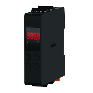
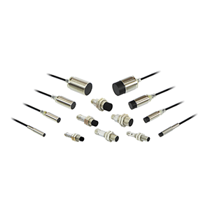
Compact Industrial SCARA
Compact Industrial Robot with light weight space saving arm. Its high speed operation is best suited for pick and place, labelling, tracking

last update: November 1, 2017
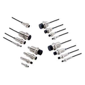
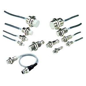
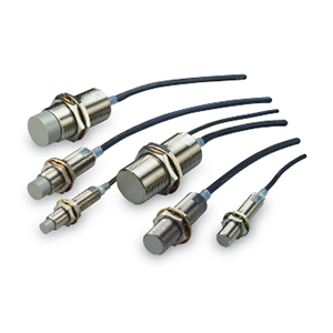
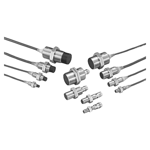
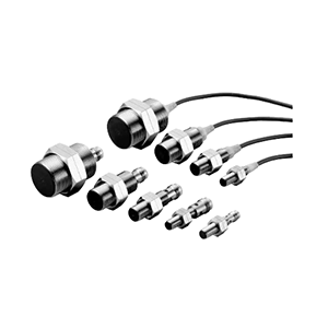
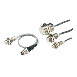
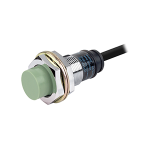
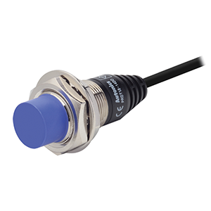
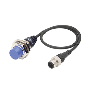
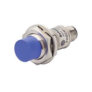
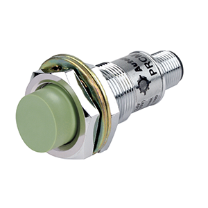
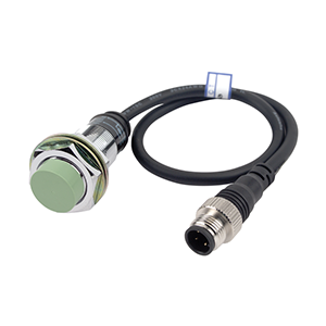
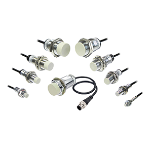
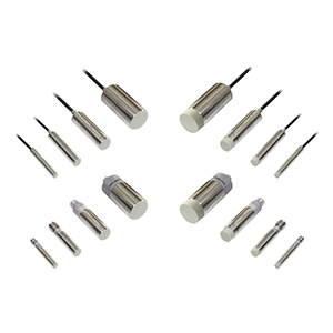
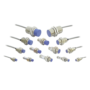
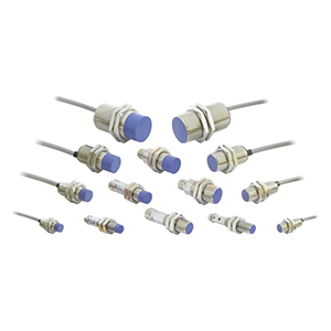
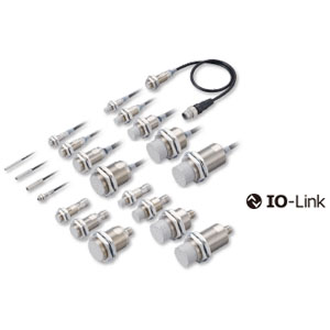
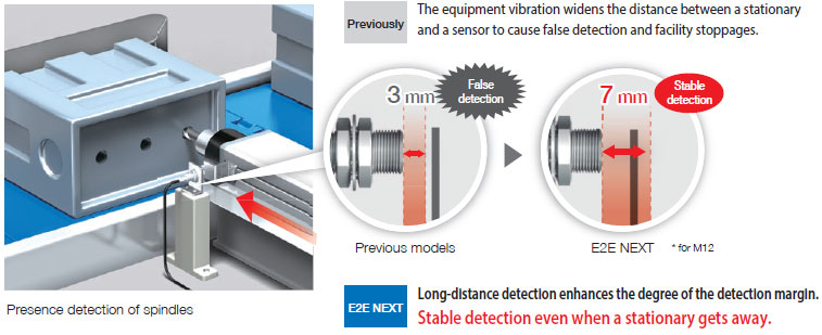
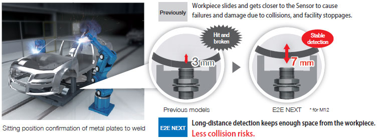
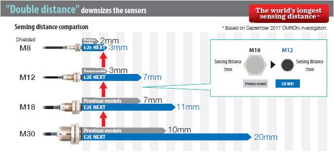
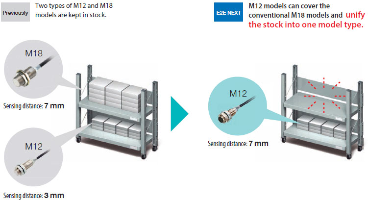
New Proximity Sensors reduce unexpected facility stoppages due to false detection, failures, and damage caused by previous proximity sensors.
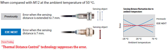
Proximity sensors with longer sensing distance require increased sensitivity. However, with the increased sensitivity, temperature changes will have bigger influence in sensing distance. E2E NEXT Proximity Sensors use "Thermal Distance Control": long-distance and stable detection technology, newly developed by OMRON.
"Thermal Distance Control" with "PROX2" write temperature correction values externally when shipped and minimize the sensing distance changes due to temperature changes, which could not be done by the conventional analog IC. It is industry's first for 2-wire proximity sensors to use analog digital hybrid IC "PROX2".
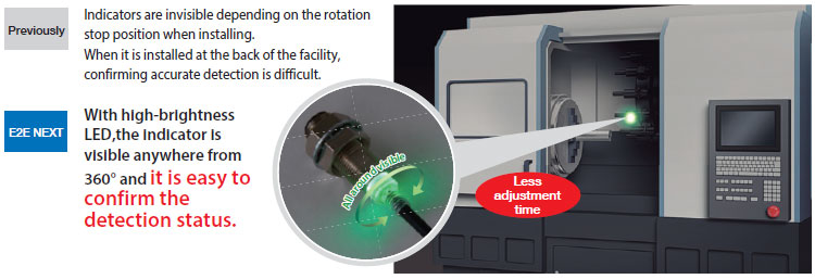
Less time required from failure to recovery (MTTR: Mean Time To Recovery).
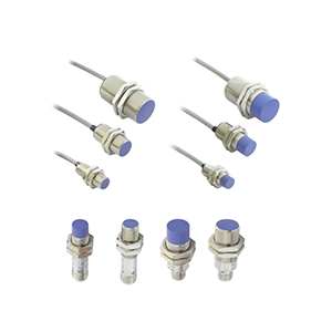
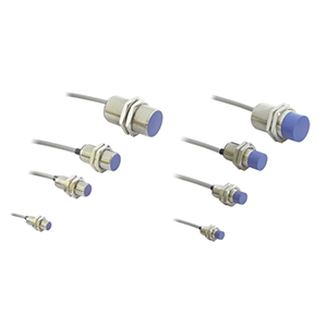
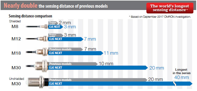
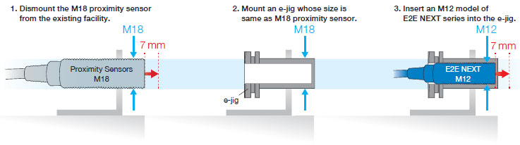
The sensing distance of E2E-NEXT is nearly double the conventional one. The sensing distance of the M12 models is 7 mm, which is same as conventional M18 models.
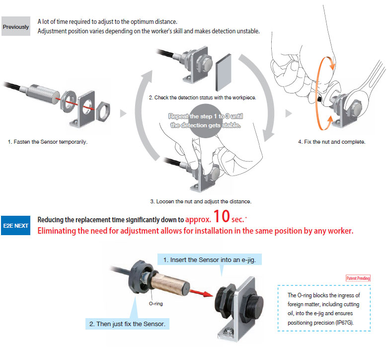
When you use an e-jig together, you can easily upgrade existing facilities to the ones that need only 10 seconds * to replace a proximity sensor.
* Time required to adjust the diistance when installing a Sensor. Based on OMRON investigation.
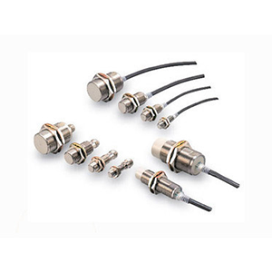
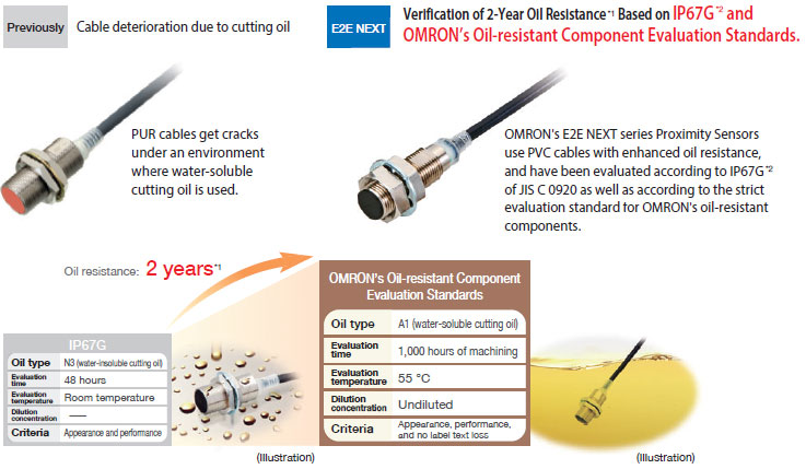
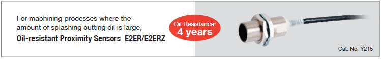
The Sensor reduces further unexpected failures in environments requiring oil resistance in addition to damage caused by collisions.
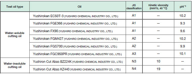
*1. · Applicable oil types: specified in JIS K 2241:2000
2-year oil resistance indicates the median value of the product design and the oil-resistance performance criterion result (=Typical value).
Products to be shipped will have around 2 years of oil resistance, but will very depending on the product.
· 2-year oil resistance is verified by Pre-wired models (2 m/5 m).
*2. The IP67G is the degree of protection which is defined according to the JIS (Japanese Industrial Standards).
The IP67 indicates the same level of protection as defined by the IEC, and the G indicates that a device has resistance to oil.
*3. pH values recommended by the cutting oil manufacturer are listed.
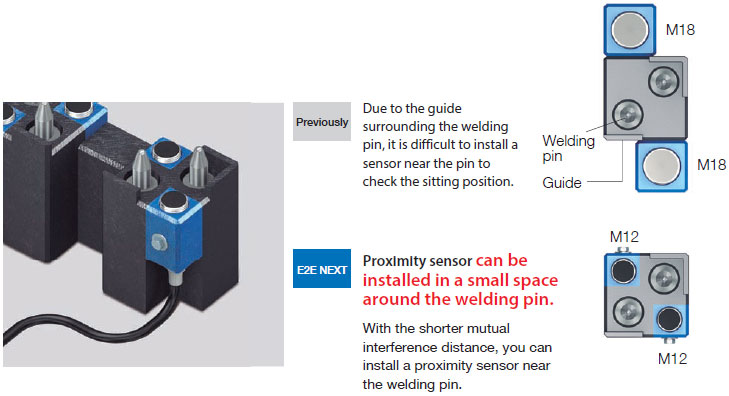
Longer sensing distance enables one size smaller sensor with the same sensing distance, so we can add more sensors to an empty space and save space for the installation.
last update: November 1, 2017
last update: November 1, 2017
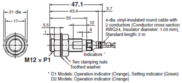
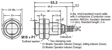
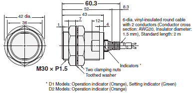
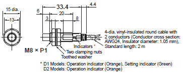
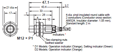
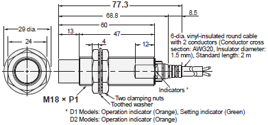
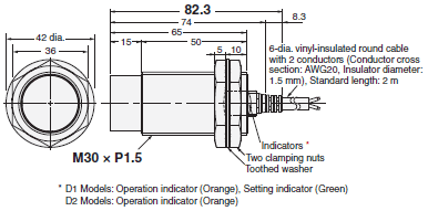
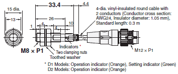
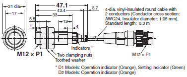
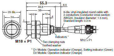
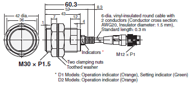
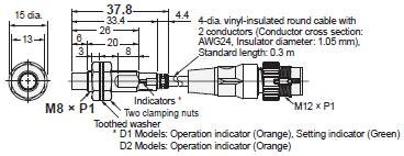
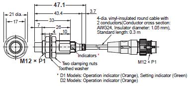
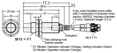
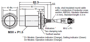
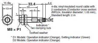
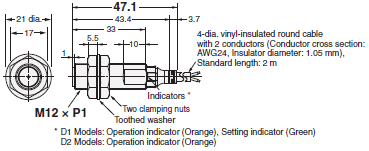
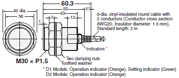
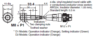
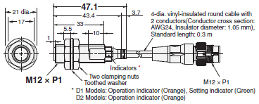
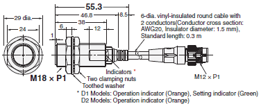
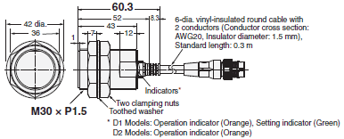
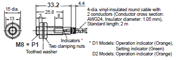
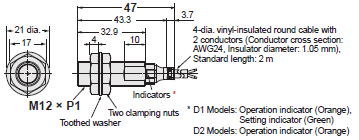
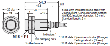
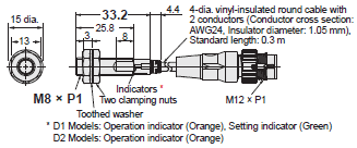
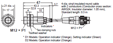
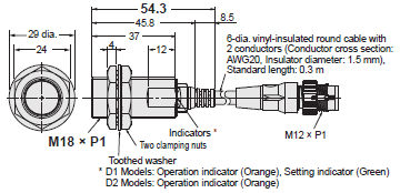
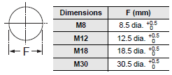
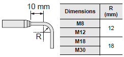
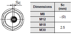
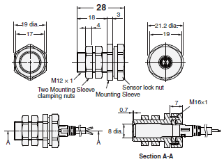
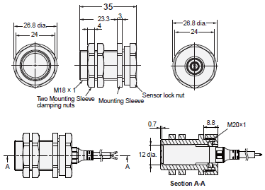
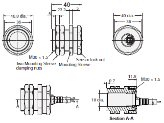
(Unit: mm)
E2E-X3D[]8
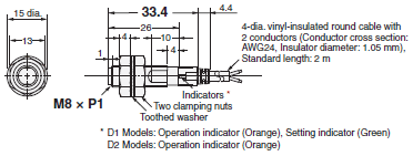
E2E-X7D[]12
E2E-X11D[]18
E2E-X20D[]30
E2E-X6MD[]8
E2E-X10MD[]12
E2E-X20MD[]L18
E2E-X40MD[]L30
E2E-X3D[]8-M1TGJ
E2E-X7D[]12-M1TGJ
E2E-X11D[]18-M1TGJ
E2E-X20D[]30-M1TGJ
E2E-X6MD[]8-M1TGJ
E2E-X10MD[]12-M1TGJ
E2E-X20MD[]L18-M1TGJ
E2E-X40MD[]L30-M1TGJ
E2EQ-X3D[]8
E2EQ-X7D[]12
E2EQ-X11D[]18
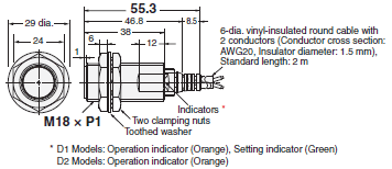
E2EQ-X20D[]30
E2EQ-X3D[]8-M1TGJ
E2EQ-X7D[]12-M1TGJ
E2EQ-X11D[]18-M1TGJ
E2EQ-X20D[]30-M1TGJ
E2E-X1R5D[]
E2E-X2R5D[]
E2E-X5D[]
E2E-X1R5D[]-M1TGJ
E2E-X2R5D[]-M1TGJ
E2E-X5D[]-M1TGJ
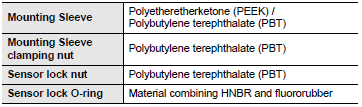
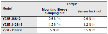
Y92E-J8S12
Y92E-J12S18
Y92E-J18S30
Sockets on One Cable End XS5F Models
Straight
Socket and Plug on Cable Ends XS5W Models
Straight/straight