Automation Systems
  Motion & Power Solutions
  Safety, Vision and IDENT
  Sensing Solutions
  Control Components
  Switching & Accessories
  Switchgear and Trolley Systems
  Process Weighing
  LED Lighting
  Omron
Omron
 Mitsubishi
 Delta
Delta
 Autonics
 Inno
Inno
 Panasonic
 Novotechnik
 Orientalmotor
 Microscan
 IPA
IPA
 Technomech
 Intech
 Honeywell
 IOT & Traceability
 Project & Panel Engg.
 Application Case Studies
 Solutions by Industry
 Solutions by Process
 Solutions by Product
 Youtube Videos
 Corporate Information
 Company Profile
 Quality Policy
 Mission Statement
 Chairman's Message
 Intech Group Companies

![E2E-[]-IL[] Features 6](upload/Images/omron/3543_fe_121-263746.jpg)
![E2E-[]-IL[] Features 7](upload/Images/omron/3543_fe_221-263745.jpg)
![E2E-[]-IL[] Features 10](upload/Images/omron/3543_fe_521-263742.jpg)
![E2E-[]-IL[] Features 13](upload/Images/omron/3543_fe_821-263738.jpg)
![E2E-[]-IL[] Features 16](upload/Images/omron/3543_fe_1121-263735.jpg)
Compact Industrial SCARA
Compact Industrial Robot with light weight space saving arm. Its high speed operation is best suited for pick and place, labelling, tracking

Downtime can be reduced.
Notifies you of faulty parts and such phenomena in the Sensor in real time.
The frequency of sudden failure can be decreased.
Notifies you of objects being too far or too close.
The efficiency of changeover can be improved.
The batch check for individual sensor IDs significantly decreases commissioning time.
Omron provides two types of Masters, a Master Unit with screw-less clamp terminal blocks and a Master Unit for M12 Smartclick connectors, as IO-Link compliant devices and Sensors for connecting to the screw-less clamp terminals or to the M12 connector terminals that support each Master.
![E2E-[]-IL[] Features 8](upload/Images/omron/3543_fe_321-263744.jpg)
∙ An abnormality was displayed on the abnormality display screen, but upon going to look at the equipment, no external error was detected and the cause of the stop was not understood...
∙ Those responsible for maintenance investigated the cause of the abnormality from the activity of the stopped equipment, but because the maintenance person relied on the skill he or she has to identify the abnormality and replace the failed sensor, stoppages from 2 hours to several days occur...
![E2E-[]-IL[] Features 9](upload/Images/omron/3543_fe_421-263743.jpg)
When an abnormality occurs in a sensor, because you can see where the abnormality occurred and the factors estimated for it, you can go to where the abnormality occurred and recover the equipment in the shortest amount of time.
Also with wire disconnection detection, not only output wires, but also power lines can be detected unconditionally.
![E2E-[]-IL[] Features 11](upload/Images/omron/3543_fe_621-263740.jpg)
The detection position changes due to wear and vibration in the device’s mechanical parts and as a result, false detection and collision with the sensor have a negative impact on the device...
![E2E-[]-IL[] Features 12](upload/Images/omron/3543_fe_721-263739.jpg)
Constantly monitoring the position of the sensing object and notifying of excessive remoteness or proximity can be used for predictive maintenance of the device.
![E2E-[]-IL[] Features 14](upload/Images/omron/3543_fe_921-263737.jpg)
∙ During system start-up or changeover, operators had to perform the I/O check for each of the thousands of sensors installed on the line, and it took an enormous amount of time...
∙ When a sensor is installed wrong or an error occurs, wasteful work occurred that would normally be unnecessary...
![E2E-[]-IL[] Features 15](upload/Images/omron/3543_fe_1021-263736.jpg)
By checking the sensor identification (manufacturer/sensor type/model number), you can easily check mistakes such as misconnected or unconnected sensors and installation mistakes.
Also, because it is possible to program multiple sensors at once using the command language used only for the controller, it is also possible to reduce commissioning time sharply.
Program all at once to reduce commissioning time and inconsistent settings
![E2E-[]-IL[] Features 17](upload/Images/omron/3543_fe_1221-263734.jpg)
Makes it possible to check for sensor installation mistakes before commissioning
![E2E-[]-IL[] Features 18](upload/Images/omron/3543_fe_1321-263747.jpg)
last update: September 12, 2016
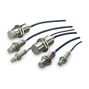
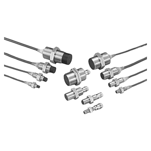
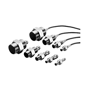
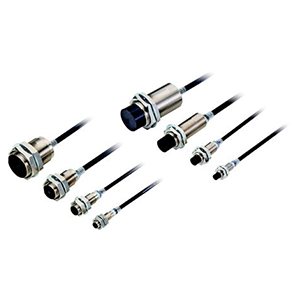
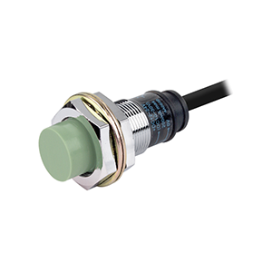
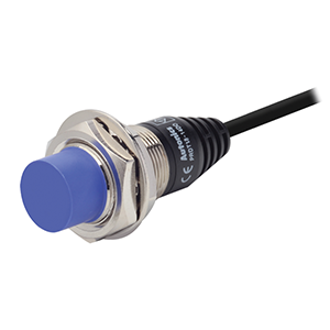
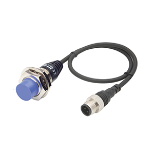
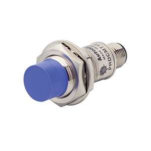
| Item | Size | M12 | M18 | M30 |
|---|---|---|---|---|
| Shielded | Shielded | |||
| Model | E2E-X3B4-IL[] | E2E-X7B4-IL[] | E2E-X10B4-IL[] | |
| Sensing distance | 3 mm ±10% | 7 mm ±10% | 10 mm ±10% | |
| Set distance *1 | 0 to 2.4 mm | 0 to 5.6 mm | 0 to 8 mm | |
| Differential travel | 10% max. of sensing distance | |||
| Detectable object | Ferrous metal
(The sensing distance decreases with non-ferrous metal. Refer to Engineering Data on Catalog.) |
|||
| Standard sensing object | Iron, 12 × 12 × 1 mm | Iron, 18 × 18 × 1 mm | Iron, 30 × 30 × 1 mm | |
| Response frequency *2 | 1 kHz | 0.5 kHz | 0.4 kHz | |
| Power supply voltage | 10 to 30 VDC (including 10% ripple (p-p)) | |||
| Current consumption | 20 mA max. | |||
| Control output | Load current | 100 mA max. | ||
| Residual voltage | 2 V max. (Load current: 100 mA, Cable length: 2 m) | |||
| Indicators *1 | In the Standard I/O mode (SIO mode): Operation indicator (orange, lit) and stability
indicator (green, lit) In the IO-Link mode: Operation indicator (orange, lit) and communication indicator (green, blinking at 1 s intervals) |
|||
| Operation mode | PNP NO/NC switching type (Factory setting: NO)
Refer to the timing charts under I/O Circuit Diagrams on Catalog for details. |
|||
| Protection circuits | Power supply reverse polarity protection, output reverse polarity protection, surge
suppressor, and output short-circuit protection |
|||
| Ambient temperature range | Operating/Storage: -25 to 70°C (with no icing or condensation) | |||
| Ambient humidity range | Operating/Storage: 35% to 95% (with no condensation) | |||
| Temperature influence | ±10% max. of sensing distance at 23°C in the temperature range of -25 to 70°C | |||
| Voltage influence | ±1% max. of sensing distance at rated voltage in the rated voltage ±15% range | |||
| Insulation resistance | 50 MΩ min. (at 500 VDC) between current-carrying parts and case | |||
| Dielectric strength | 1,000 VAC, 50/60 Hz for 1 minute between current-carrying parts and case | |||
| Vibration resistance | Destruction: 10 to 55 Hz, 1.5-mm double amplitude for 2 hours each in X, Y, and Z
directions |
|||
| Shock resistance | Destruction: 1,000 m/s2 10 times each in X, Y, and Z directions | |||
| Degree of protection | IEC 60529 IP67, in-house standards: oil-resistant *3 | |||
| Connection method | Pre-wired Models (Standard cable length: 2 m), Pre-wired Connector Models
(Standard cable length: 0.3 m) |
|||
| Materials | Case | Nickel-plated brass | ||
| Sensing surface | PBT | |||
| Clamping nuts | Nickel-plated brass | |||
| Toothed washer | Zinc-plated iron | |||
| Main IO-Link functions | Operation mode switching between NO and NC, self diagnosis enabling, excessive
proximity judgment distance selecting, timer function of the control output and timer time selecting, instability output (IO-Link mode) ON delay timer time selecting function, monitor output, operating hours read-out, and initial reset |
|||
| Communication
specifications |
IO-Link
specification |
Ver 1.1 | ||
| Baud rate | -IL3: COM3 (230.4 kbps), -IL2: COM2 (38.4 kbps) | |||
| Data length | PD size: 2 bytes, OD size: 1 byte (M-sequence type: TYPE_2_2) | |||
| Minimum cycle
time |
-IL3 (COM3): 1 ms, -IL2 (COM2): 2.3 ms | |||
| Accessories | Instruction manual | |||
Note: Please contact your OMRON sales representative regarding the IO-Link setup file (IODD file).
*1. In the Standard I/O mode (SIO mode), use the product in a range that the green stability indication lamp is lit. (Although the lamp is turned off when the object detected has approached excessively, the detection performance is stable.)
In the IO-Link mode, use the product in a range that the Byte1_bit4 for instability detection is zero. (Although the Byte1_bit5 for excessive proximity detection is one if the object detected has approached excessively, the detection performance is stable.) Please contact your OMRON sales representative regarding assignment of data.
*2. The response frequency is an average value. Measurement conditions are as follows: standard sensing object, a distance of twice the standard sensing object, and a set distance of half the sensing distance.
*3. Oil resistance in-house standard: Performance with respect to water insoluble oil.
(Test at below)
After the test time elapses, the characteristics below are checked for problems.
(1) Visual appearance (no damage that affects product characteristics)
(2) Operation check (ON/OFF) (3) Insulation resistance (50 MΩ min. at 500 VDC)
(4) Dielectric strength (500 VAC, 1 min.)
(5) Water resistance (IP67)
![E2E-[]-IL[] Specifications 3](upload/Images/omron/3543_sp_221-261950.gif)
last update: September 12, 2016
![E2E-[]-IL[] Dimensions 2](upload/Images/omron/3543_dm_121-261951.gif)
*1. 4-dia. vinyl-insulated round cable with 3 conductors (Conductor cross section: 0.3 mm2, Insulator diameter: 1.3 mm), Standard length: 2 m
*2. Operation indicator (orange), stability indicator/communication indicator (green)
![E2E-[]-IL[] Dimensions 3](upload/Images/omron/3543_dm_221-261952.gif)
*1. 6-dia. vinyl-insulated round cable with 3 conductors (Conductor cross section: 0.5 mm2, Insulator diameter: 1.9 mm), Standard length: 2 m
*2. Operation indicator (orange), stability indicator/communication indicator (green)
![E2E-[]-IL[] Dimensions 4](upload/Images/omron/3543_dm_321-261953.gif)
*1. 6-dia. vinyl-insulated round cable with 3 conductors (Conductor cross section: 0.5 mm2, Insulator diameter: 1.9 mm), Standard length: 2 m
*2. Operation indicator (orange), stability indicator/communication indicator (green)
![E2E-[]-IL[] Dimensions 6](upload/Images/omron/3543_dm_421-261954.gif)
*1. 4-dia. vinyl-insulated round cable Standard length: 0.3 m
*2. Operation indicator (orange), stability indicator/communication indicator (green)
![E2E-[]-IL[] Dimensions 7](upload/Images/omron/3543_dm_521-261955.gif)
*1. 6-dia. vinyl-insulated round cable Standard length: 0.3 m
*2. Operation indicator (orange), stability indicator/communication indicator (green)
![E2E-[]-IL[] Dimensions 8](upload/Images/omron/3543_dm_621-261943.gif)
*1. 6-dia. vinyl-insulated round cable Standard length: 0.3 m
*2. Operation indicator (orange), stability indicator/communication indicator (green)
![E2E-[]-IL[] Dimensions 9](upload/Images/omron/3543_dm_721-261944.gif)