Automation Systems
  Motion & Power Solutions
  Safety, Vision and IDENT
  Sensing Solutions
  Control Components
  Switching & Accessories
  Switchgear and Trolley Systems
  Process Weighing
  LED Lighting
  Omron
Omron
 Mitsubishi
 Delta
Delta
 Autonics
 Inno
Inno
 Panasonic
 Novotechnik
 Orientalmotor
 Microscan
 IPA
IPA
 Technomech
 Intech
 Honeywell
 IOT & Traceability
 Project & Panel Engg.
 Application Case Studies
 Solutions by Industry
 Solutions by Process
 Solutions by Product
 Youtube Videos
 Corporate Information
 Company Profile
 Quality Policy
 Mission Statement
 Chairman's Message
 Intech Group Companies

Compact Industrial SCARA
Compact Industrial Robot with light weight space saving arm. Its high speed operation is best suited for pick and place, labelling, tracking
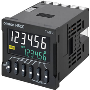

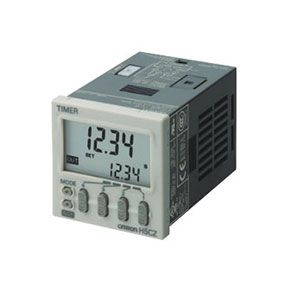
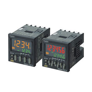
The H5CC series improves overall user experience through better visual feedback and operation, user interface and predictive remaining lifetime of timer.


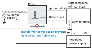
Power supply and input have been isolated, eliminating special considerations for grounding or leakage current.
(except H5CC-A11F)
When a timer’s service life expires, there are multiple ways it can potentially fail. For example, it may stop suddenly or become incapable of performing certain control functions.
Preventative maintenance to avoid such mechanical failures or identifying the cause when such a failure occurs, may require a significant effort and time.
When an H5CC Series timer reaches its replacement time, it will visually notify the user via its display by flashing the present value and “RPLC” alternately in one second intervals.
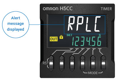
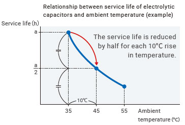
The rate at which an electrolytic capacitor deteriorates varies according to its use environment. Omron offers a tool that allows you to easily calculate your H5CC timer’s replacement time, according to the conditions your using it in.
Each timer has its limited service life.
The standard service life of a relay output contact is 100,000 operations. Factoring in the deterioration of the built-in electrolytic capacitors, Omron recommends that a timer be replaced approximately every 7 to 10 years depending on environment. A timer that is used beyond its service life may fail, potentially emitting smoke or odor.
*1. Compared with the previous products
*2. The AC power supply ground is on the commercial power supply side.
| Item | Models | H5CC-A[] | H5CC-A11[] | H5CC-L8[] |
|---|---|---|---|---|
| Classification | Standard Type | Economy Type | ||
| Ratings | Power supply
voltage *1 |
• 100 to 240 VAC 50/60 Hz
• 12 to 48 VDC/24 VAC 50/60 Hz • 24 to 240 VDC/24 to 240 VAC 50/60 Hz (only for the H5CC-[]F) |
||
| Allowable voltage fluctuation range | 85% to 110% of rated supply voltage (90% to 110% at 12 to 48 VDC) | |||
| Power consumption | Approx.6.5 VA at 100 to 240 VAC
Approx.5.4 VA/3.2 W at 24 VAC/12 to 48 VDC Approx. 5.6 VA/2.7 W at 24 to 240 VAC/24 to 240 VDC *2 |
|||
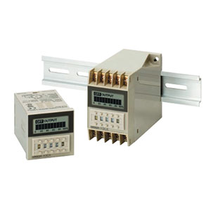
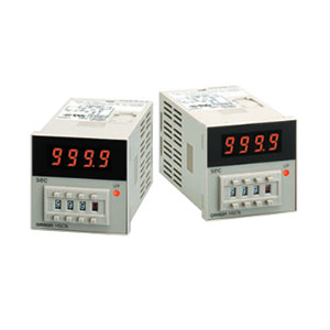
| Mounting method | Flush mounting | Flush mounting, surface mounting, DIN track mounting | ||
| External connections | Screw terminals | 11-pin socket | 8-pin socket | |
| Degree of protection | IEC IP66 for panel surface only and when Y92S-P6 Waterproof Packing is used | |||
| Digits | 6 digits | |||
| Time ranges | 0.001 s to 999.999 s, 0.01 s to 9999.99 s, 0.1 s to 99999.9 s, 1 s to 999999 s, 1 s to 99 h 59 min 59 s, 0.1 m to 99999.9 min, 1 min to 999999 min, 1 min to 9999 h 59 min, 0.1 h to 99999.9 h, 1 h to 999999 h | |||
| Timer mode | Elapsed time (Up), remaining time (Down) (selectable) | |||
| Inputs | Input signals | Signal, Reset, Gate | Signal, Reset
(no inputs on the H5CC-L8E[]) |
|
| Input method | No-voltage (NPN) input/voltage (PNP) input
(switchable)
(only no-voltage input is available for the H5CC-A11F) No-voltage input ON impedance: 1 kΩ max. (Leakage current: approx. 12 mA when 0 Ω) (Approx. 1 mA for the H5CC-A11F) ON residual voltage: 3 V max. (1 V max. for the H5CC-A11F) OFF impedance: 100 kΩ min. Voltage input High (logic) level: 4.5 to 30 VDC Low (logic) level: 0 to 2 VDC (Input resistance: approx. 4.7 kΩ) |
No-voltage input
On-impedance: 1 kΩ max. (Leakage current: 12 mA when 0 Ω) ON residual voltage: 3 V max. OFF impedance: 100 kΩ min. |
||
| Signal, reset, gate | Minimum input signal width: 1 or 20 ms (selectable, 50 ms for the H5CC-A11F) | |||
| Reset system | Power reset (depending on output mode),
external reset, manual reset, automatic reset (depending on output mode) |
|||
| Power reset | Minimum power-opening time: 0.5 s (except for
A-3, b-1, F, ton-1, and toff-1 mode)
(1 s for the H5CC-AU[] and 0.1 s for the H5CC-[]F) |
|||
| Reset voltage | 10% max. of power supply voltage | |||
| Sensor waiting time | 250 ms max.
(Control output is turned OFF and no input is accepted during sensor waiting time.) |
|||
| Output | Output modes | A: Signal ON delay I, A-1: Signal ON delay II,
A2: Power ON delay I, A3: Power ON delay II, b: Flicker I, b-1: Flicker II, b-5: One-shot
flicker, C: Signal ON/OFF delay I, d: Signal OFF delay I, E: Interval, F: Cumulative, G:
Signal ON/OFF delay II, H: Signal OFF delay II, Z: ON/OFF-duty-adjustable flicker, S:
Stopwatch, toff: Flicker
OFF start I, ton: Flicker ON start I, toff-1: Flicker OFF start II, ton-1: Flicker ON start II |
||
| H5CC-L8E[]
A2: Power ON delay I, b: Flicker I, E: Interval, Z: ON/OFF-duty-adjustable flicker, toff: Flicker OFF start I, ton: Flicker ON start I |
||||
| One-shot time | 0.01 to 99.99 s | |||
| Control output | • Models with Contact Outputs
5 A at 250 VAC/30 VDC, resistive load (cos =1) Minimum applicable load: 10 mA at 5 VDC (failure level: P, reference value) Contact materials: AgSnIn • Transistor output: NPN open collector, 100 mA at 30 VDC max., residual voltage: 1.5 VDC max. (Approx. 1 V), Leakage current: 0.1 mA max. |
|||
| External power supply | 12 VDC (±10%), 100 mA (only for the H5CC-AU[])
Note. Refer to Precautions for Correct Use on Data Sheet for details. |
|||
| Display method *3 | 7-segment, negative transmissive LCD;
Present value: 10-mm-high characters, white Set value: 6-mm-high characters, green |
7-segment, negative transmissive LCD;
Present value: 10-mm-high characters, white Set value: 6-mm-high characters, green |
||
| Memory backup | No-volatile memory (overwrites: 100,000 times min.) that can store data for 10 years min. | |||
| Operating temperature range | -10 to 55°C
(-10 to 50°C if timers are mounted side by side) (with no icing or condensation) |
|||
| Storage temperature range | -25 to 70°C (with no icing or condensation) | |||
| Operating humidity range | 25% to 85% | |||
| Case color | Black (N1.5) | |||
| Attachments | Flush mounting adapter,
waterproof packing, terminal cover |
―― | ||
*1. Do not use the output from an inverter as the power supply. The ripple must be 20% maximum for DC
power.
*2. Inrush current will flow for a short time when the power supply is turned ON.
Inrush Current (Reference Values)
| Voltage | Applied voltage | Inrush current (peak value) | Time |
|---|---|---|---|
| 100 to 240 VAC | 264 VAC | 6.5 A | 0.74 ms |
| 12 to 48 VDC/24 VAC | 26.4 VAC | 13.6 A | 0.88 ms |
| 52.8 VDC | 12.9 A | 0.80 ms | |
| 24 to 240 VDC/24 to 240 VAC | 264 VAC | 5.5 A | 0.26 ms |
| 264 VDC | 3.9 A | 0.26 ms |
*3. The display is lit only when the power is ON. Nothing is displayed when power is OFF.
| Item | Models | H5CC-AWSD |
|---|---|---|
| Classification | Digital Timer with two-stage setting, and forecast output | |
| Ratings | Power supply voltage | 12 to 48 VDC/24 VAC 50/60 Hz |
| Allowable voltage fluctuation range | 85% to 110% of rated supply voltage (90% to 110% at 12 to 48 VDC) | |
| Power consumption | Approx. 5.32 VA/3.17 W at 24 VAC/12 to 48 VDC *1 | |
| Mounting method | Flush mounting | |
| External connections | Screw terminals | |
| Degree of protection | IEC IP66 for panel surface only and when Y92S-P6 Waterproof Packing is used | |
| Time range | 0.001 s to 999.999 s, 0.01 s to 9999.99 s, 0.1 s to 99999.9 s, 1 s to 999999 s, 1 s to 99 h 59 min 59 s, 0.1 min to 99999.9 min, 1 min to 999999 min, 1 min to 9999 h 59 min, 0.1 h to 99999.9h, 1 h to 999999 h | |
| Timer mode | Elapsed time (Up) | |
| Inputs | Input signals | Signal, reset, gate |
| Input method | No-voltage (NPN) input/voltage (PNP) input (switchable)
No-voltage input ON impedance: 1 kΩ max. (Leakage current: 12 mA when 0 Ω) ON residual voltage: 3 V max. OFF impedance: 100 kΩ min. Voltage input High (logic) level: 4.5 to 30 VDC Low (logic) level: 0 to 2 VDC (Input resistance: approx. 4.7 kΩ) |
|
| Signal, reset, gate | Minimum input signal width: 1 or 20 ms (selectable, same for all input) | |
| Reset system | Power resets (only for A mode), external and manual reset | |
| Power reset | Minimum power-opening time: 0.5 s (except for F-1 mode) | |
| Reset voltage | 10% max. of power supply voltage | |
| Sensor waiting time | 250 ms max.
(Control output is turned OFF and no input is accepted during sensor waiting time.) |
|
| Outputs | Output modes | A, F-1 |
| Output type | Transistor output: NPN open collector,
100 mA at 30 VDC max. residual voltage: 1.5 VDC max. (Approx. 1 V) Leakage current: 0.1 mA max. |
|
| Display | 7-segment, negative transmissive LCD;
Present value: 10-mm-high characters, white Set value: 6-mm-high characters, green *2 |
|
| Memory backup | No-volatile memory (overwrites: 100,000 times min.)
that can store data for 10 years min. |
|
| Operating temperature range | -10 to 55°C (-10 to 50°C if timers are mounted side by side)
(with no icing or condensation) |
|
| Storage temperature range | -25 to 70°C (with no icing or condensation) | |
| Operating humidity range | 25% to 85% | |
| Case color | Black (N1.5) | |
| Attachments | Waterproof packing, flush mounting adapter, terminal cover | |
*1.Inrush current will flow for a short time when the power supply is turned ON.
Inrush Current (Reference Values)
| Voltage | Applied voltage | Inrush current (peak value) | Time |
|---|---|---|---|
| 12 to 48 VDC/24 VAC | 52.8 VAC | 13.6 A | 0.88 ms |
| 42.8 VDC | 12.9 A | 0.80 ms |
*2.The display is lit only when the power is ON. Nothing is displayed when power is OFF.
| Accuracy of operating time and
setting error
(including temperature and voltage influences) |
Power-ON start: ±0.01%±0.05 s max. *1
Signal start: ±0.005%±0.03 s max. *1 Signal start for transistor output model: ±0.005%±3 ms max. *1 *2 If the set value is within the sensor waiting time at startup the control output of the H5CC will not turn ON until the sensor waiting time passes. *1.The values are based on the set value. *2.The value is applied for a minimum input signal width of 1 ms. |
|
|---|---|---|
| Insulation resistance | 100 MΩ min. (at 500 VDC)
between current-carrying terminal and exposed non-current-carrying metal parts, between non-continuous contacts |
|
| Dielectric strength | 2,900 VAC, 50/60 Hz for 1 min between current-carrying terminal and
operating section
2,000 VAC, 50/60 Hz for 1 min between power supply and input circuits for models other than the H5CC-A11F and H5CC-L8E[] (1,500 VAC for 12 to 48 VDC/24 VAC) 1,500 VAC, 50/60 Hz for 1 min between control output, power supply, and input circuits (for models other than the H5CC-L8E[]) for H5CC-[]SD 2,000 VAC, 50/60 Hz for 1 min between control output, power supply, and input circuits (for models other than the H5CC-L8E[]) for other models 1,000 VAC, 50/60 Hz for 1 min between non-continuous contacts |
|
| Impulse withstand voltage | 5 kV (between power terminals) for 100 to 240 VAC, 1.0 kV for 24 VAC/12
to 48 VDC
7.4 kV (between current-carrying terminal and operating section) |
|
| Static immunity | Malfunction: 8 kV
Destruction: 15 kV |
|
| Vibration resistance | Destruction | 10 to 55 Hz with 0.75-mm single amplitude each in three directions for 2 h each |
| Malfunction | 10 to 55 Hz with 0.35-mm single amplitude each in three directions for 10 min each | |
| Shock resistance | Destruction | 300 m/s2 in three directions, three cycles |
| Malfunction | 100 m/s2 in three directions, three cycles | |
| Life expectancy | Mechanical | 10,000,000 operations min.
(under no load at switching frequency of 1,800 operations/h and ambient temperature of 23°C) |
| Electrical | 100,000 operations min.
(5 A at 250 VAC, resistive load at 1,800 operations/h and ambient temperature of 23°C) * |
|
| Weight | Approx. 115 g (Timer only) | |
*Refer to Electrical Life Test Curve.
| Approved safety standards | cULus (or cURus): UL508/CSA C22.2 No. 14 *1
Conforms to EN61812-1: Pollution degree 2/overvoltage category III B300 PILOT DUTY, 1/4 HP 120 VAC, 1/3 HP, 240 VAC, 5 A, 250 VAC/30 VDC resistive load VDE0106/P100 CCC: GB/T 14048.5 Pollution degree 2/overvoltage category III *2 RCM UKCA |
|---|---|
| EMC | (EMI) EN61812-1
Emission Enclosure: EN55011 Group 1 class A Emission AC mains: EN55011 Group 1 class A (EMS) EN61812-1 Immunity ESD: EN61000-4-2: 4 kV contact discharge 8 kV air discharge Immunity RF-interference: EN61000-4-3: 10 V/m (Amplitude modulated, 80 MHz to 1 GHz); 3 V/m (Amplitude modulated, 1.4 G to 2 GHz); 1 V/m (Amplitude modulated, 2 G to 2.7 GHz); 10 V/m (Pulse-modulated, 900 MHz±5 MHz) Immunity Conducted Disturbance: EN61000-4-6: 10 V (0.15 to 80 MHz) Immunity Burst: EN61000-4-4: 2 kV power-line; 1 kV I/O signal-line Immunity Surge: EN61000-4-5: 1 kV line to lines (power and output lines (relay outputs)); 2 kV line to ground (power and output lines (relay outputs)) Immunity Voltage Dip/Interruption: EN61000-4-11: Voltage Dip 1 cycle, 100% (rated voltage) 10/12 cycle, 60% (rated voltage) 25/30 cycle, 30% (rated voltage) Interruption 250/300 cycle, 100% (rated voltage) |
*1.The following safety standards apply to models with sockets (H5CC-L8[]/-A11[]).
cUL (Listing): Applicable when an OMRON P2CF(-E) Socket is used.
cUR (Recognition): Applicable when any other socket is used.
*2.CCC certification requirements
| Rated operating voltage Ue
Rated operating current Ie |
Contact output:
AC-15: Ue: 250 VAC, Ie: 3 A AC-13: Ue: 250 VAC, Ie: 5 A DC-13: Ue: 30 VDC, Ie: 0.5 A Transistor output: DC-13: Ue: 30 VDC, Ie: 0.1 A |
|---|---|
| Rated insulation voltage | 250 V |
| Rated impulse withstand voltage
(altitude: 2,000 m max.) |
4 kV (at 240 VAC) |
| Conditional short-circuit current | 1000 A |
For details, refer to the timing charts on Data Sheet.
| Inputs *1 | Start signal | Normally functions to start timing.
In modes A-2 and A-3, disable timing. In mode S, starts and stops timing. |
|
|---|---|---|---|
| Reset | •Resets present value. (In elapsed time mode, the present value returns
to 0; in remaining time mode, the present value returns to the set value.)
•Count inputs are not accepted and control output turns OFF while reset input is ON. •Reset indicator is lit while reset input is ON. |
||
| Gate *2 | Disables timing. (If a reset occurs while the gate input is ON, a reset will be performed.) | ||
| Outputs | Control output (OUT) | Outputs take place according to designated operating mode when timer reaches corresponding set value. | |
| Forecast value setting *3 | Control output (OUT2) | Turns ON when the present value reaches the set value. | |
| Forecast output (OUT1) | Turns ON when the present value reaches the forecast value. | ||
| Absolute value setting *3 | Control output 2 (OUT2) | Turns ON when the present value reaches the set value 2. | |
| Control output 1 (OUT1) | Turns ON when the present value reaches the set value 1. | ||
*1.The H5CC-L8E[] does not have an input.
*2.The H5CC-L[] does not have a gate input.
*3.For the H5CC-AWSD.
The following table shows the output delay time from when the reset signal is input until the output is
turned OFF.
(Reference value)
| Minimum reset signal width | Output delay time |
|---|---|
| 1 ms | 0.58 to 0.78 ms |
| 20 ms | 13.7 to 17.2 ms |
(Unit: mm)
H5CC-A/-AD/-AS/-ASD/-AU/-AUD/-AWSD (Flush Mounting Models)
Note: M3.5 terminal screw (effective length: 6 mm)
H5CC-A11/-A11D/-A11F/-A11S/-A11SD (Flush Mounting/Surface Mounting Models)
H5CC-L8/-L8D/-L8S/-L8SD/-L8E/-L8ED/-L8EF (Flush Mounting/Surface Mounting Models)
H5CC-A/-AD/-AS/-ASD/-AU/-AUD/-AWSD (Flush Mounting Models)
(Provided with Adapter and Waterproof Packing)
H5CC-L8/-L8D/-L8S/-L8SD/-L8E/-L8ED/-L8DF/-A11/-A11D/-A11F/-A11S/-A11SD (Flush Mounting Models)
(Adapter and Waterproof Packing Ordered Separately)
Panel cutouts are as shown below. (According to DIN 43700.)
Note: 1. The mounting panel thickness should be 1 to 5 mm.
Note: 2. To allow easier operation, it is recommended that Adapters be mounted so that the gap between sides with hooks is at least 15 mm (i.e., with the panel cutouts separated by at least 60 mm).
Note: 3. It is possible to horizontally mount Timers side by side. Attach the Flush Mounting Adapters so that the surfaces without hooks are on the sides of the Timers. If they are mounted side-by-side, water resistance will be lost.
* These dimensions depend on the kind of DIN track and Sockets. (Reference value.)
Note: Depending on the operating environment, the condition of resin products may deteriorate, and may shrink or become harder. Therefore, it is recommended that resin products are replaced regularly.
Soft Cover
Y92A-48F1

The Soft Cover is attached by inserting the front part between the holding clips.
Hard Cover
Y92A-48

The H5CC’s panel surface is water-resistive (IP[]6) and so even if drops of water penetrate the gaps between the keys, there will be no adverse effect on internal circuits. If, however, there is a possibility of oil being present on the operator’s hands, use the Soft Cover. The Soft Cover ensures protection equivalent to IP54 against oil. Do not, however, use the H5CC in locations where the front section would come in direct contact with oil.
Waterproof Packing
Y92S-P6

* The Waterproof Packing is included with models with screw terminals.
Order the Waterproof Packing separately if it is lost or damaged.
The Waterproof Packing can be used to achieve IP66 protection.
The Waterproof Packing will deteriorate, harden, and shrink depending on the application environment. To ensure maintaining the IP[]6 waterproof level, periodically replace the Waterproof Packing.
The periodic replacement period will depend on the application environment. You must confirm the proper replacement period. Use one year or less as a guideline. If the Waterproof Packing is not replaced periodically, the waterproof level will not be maintained.
It is not necessary to mount the Waterproof Packing if waterproof construction is not required.
Flush Mounting Adapter
Y92F-30

Order the Flush Mounting Adapter separately if it is lost or damaged.
Note: A Flush Mounting Adapter is included with models with screw terminals.
Y92F-38
* Insert the timer unit from front side of adapter.
* Use Waterproof Packing to provide a level of water protection that complies with IP[]6 standards.
* It is not necessary to mount the Waterproof Packing if waterproof construction is not required.
Waterproof Packing
Y92S-35
The Y92S-35 is not provided with the Y92F-38. Order separately, if water protection is required. Use Waterproof Packing to provide a level of water protection that complies with IP65 standards.
Depending on the operating environment, the Waterproof Packing may deteriorate, contract, or harden and so regular replacement is recommended. The periodic replacement period will depend on the application environment. You must confirm the proper replacement period. Use one year or less as a guideline. If the Waterproof Packing is not replaced periodically, the waterproof level will not be maintained.
Y92F-45
Note: 1. The adapter is black in color.
Note: 2. The Y92F-45 can be used in combination with the Y92F-30 Adapter provided with the Timer.
H5CC Mounting Example
P2CF-08
P2CF-08-E
(Finger-safe Type)
P2CF-11
P2CF-11-E
(Finger-safe Type)
Note: Round crimp terminals cannot be used on Finger-safe Sockets. Use forked crimp terminals.
The P2CF has hooks to fix the timer so the holding clips are not required.
P3G-08
P3GA-11
Note: A Y92A-48G Terminal Cover can be used with the Socket to enable finger protection.
Y92A-48G
Note: The Terminal Cover can be used with a Back Connecting Socket (P3G-08 or P3GA-11) to enable finger protection.
Mounting Track
PFP-100N
PFP-50N
Mounting Track
PFP-100N2
End Plate
PFP-M
Spacer
PFP-S
Note: Order Spacers in increments of 10. The above prices are the standard prices for one item.