Automation Systems
  Motion & Power Solutions
  Safety, Vision and IDENT
  Sensing Solutions
  Control Components
  Switching & Accessories
  Switchgear and Trolley Systems
  Process Weighing
  LED Lighting
  Omron
Omron
 Mitsubishi
 Delta
Delta
 Autonics
 Inno
Inno
 Panasonic
 Novotechnik
 Orientalmotor
 Microscan
 IPA
IPA
 Technomech
 Intech
 Honeywell
 IOT & Traceability
 Project & Panel Engg.
 Application Case Studies
 Solutions by Industry
 Solutions by Process
 Solutions by Product
 Youtube Videos
 Corporate Information
 Company Profile
 Quality Policy
 Mission Statement
 Chairman's Message
 Intech Group Companies

Compact Industrial SCARA
Compact Industrial Robot with light weight space saving arm. Its high speed operation is best suited for pick and place, labelling, tracking

last update: March 14, 2013

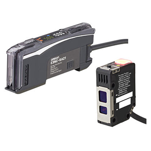
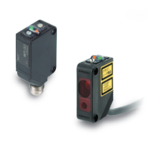
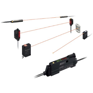
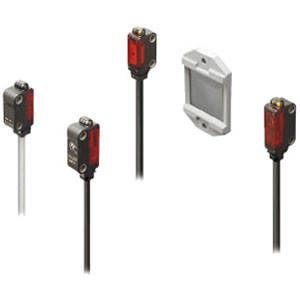
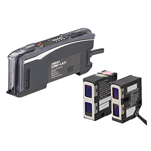
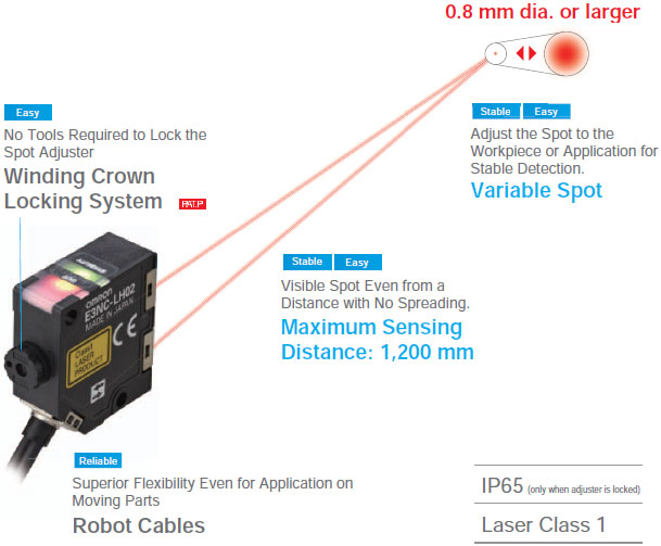
Long Distance, Variable Spot
E3NC-LH02

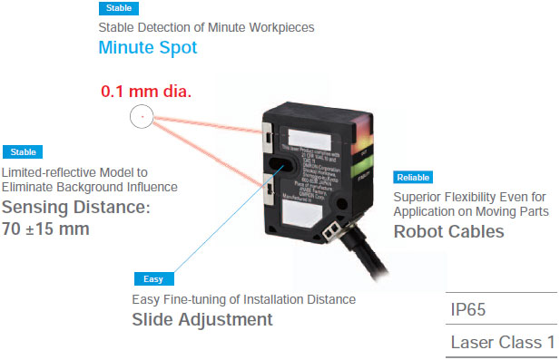
Minute Spot
E3NC-LH01

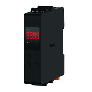
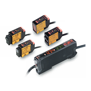
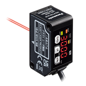
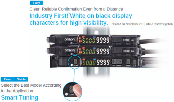
Laser Amplifier Units
E3NC-LA
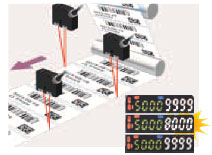
The larger incident level between measurements with and without a workpiece is set to 9,999.
Press  once with a workpiece.
Press once without a workpiece.

The values are displayed together to immediately show changes in incident levels.
High-precision, pinpoint workpiece positioning is possible.
Press once without a workpiece.
Place workpiece in desired position and press for at least 3 seconds.
You can adjust to moving workpieces without stopping the line.
Press for at least 7 seconds without a workpiece. When  , appears on the green digital display, send a workpiece pass the Sensor. Release your finger after the workpiece passes.

Easy, Dependable Setup for Detection of Minute Moving Workpieces
Solution Viewer (PAT.P)
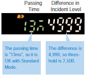
The passing time and difference in incident level are displayed when a workpiece passes. The display of the differences in incident level lets you determine if the threshold is the best. The display of the passing time lets you determine if the response time is best so that you can achieve reliable operation.
last update: March 14, 2013
Tolerance class IT16 applies to dimensions in this data sheet unless otherwise specified.
* When adjusted, the adjuster extends 0.8 mm from the Mounting Bracket surface.
Material: Stainless steel (SUS304)
Material: Aluminum
*Dimensions in parentheses are for the PFP-50N.
Material: Aluminum
Materials: Iron, zinc plating