Automation Systems
  Motion & Power Solutions
  Safety, Vision and IDENT
  Sensing Solutions
  Control Components
  Switching & Accessories
  Switchgear and Trolley Systems
  Process Weighing
  LED Lighting
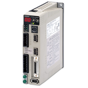
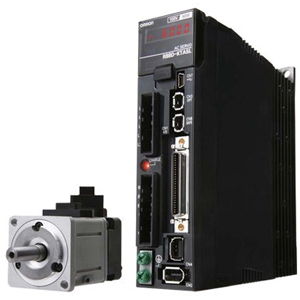
  Omron
Omron
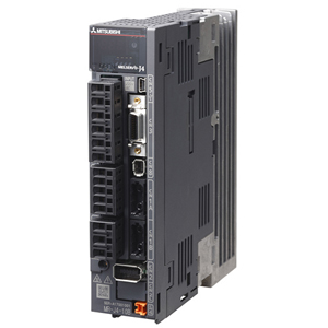
 Mitsubishi
 Delta
Delta
 Autonics
 Inno
Inno
 Panasonic
 Novotechnik
 Orientalmotor
 Microscan
 IPA
IPA
 Technomech
 Intech
 Honeywell
 IOT & Traceability
 Project & Panel Engg.
 Application Case Studies
 Solutions by Industry
 Solutions by Process
 Solutions by Product
 Youtube Videos
 Corporate Information
 Company Profile
 Quality Policy
 Mission Statement
 Chairman's Message
 Intech Group Companies

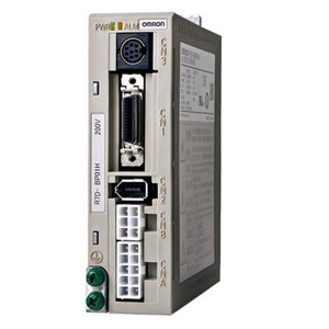
Compact Industrial SCARA
Compact Industrial Robot with light weight space saving arm. Its high speed operation is best suited for pick and place, labelling, tracking

last update: December 16, 2013
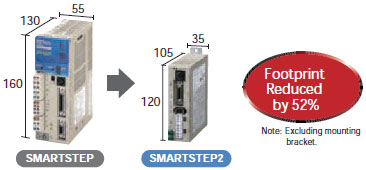
The super-compact SMARTSTEP is now even smaller.
The footprint has been reduced by 52%, helping to reduce control panel size.
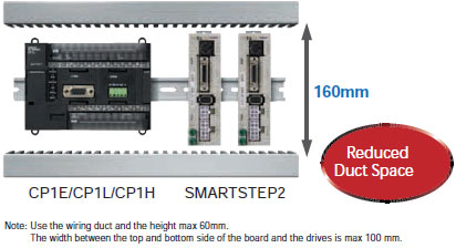
SMARTSTEP2 is only 120 mm in height. By mounting it onto the same duct as the compact CP1L PLC, the duct pitch can be reduced, minimizing control panel space.
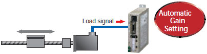
An autotuning function calculates the device load in realtime and automatically sets the optimum gain, simplifying the adjustment procedure.
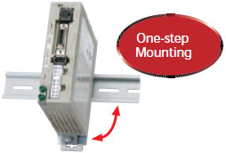
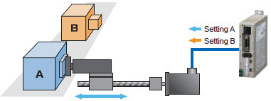
The Servo Drive can be mounted onto a DIN Rail in a single step by using the DIN Rail Mounting Unit (sold separately) for easier assembly and easier maintenance replacements.
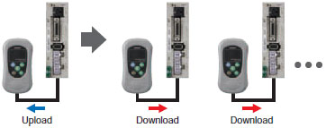
Parameter can be easily set for many Servo Drives using the Parameter Unit, enabling easier assembly work in mass production lines.
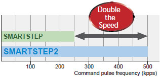
The command pulse frequency at 500 kpps is twice as fast as previous OMRON models, enabling high-speed and high-precision control.
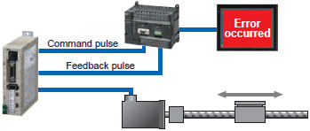
The present position can be checked from the host using the feedback pulse sent from the Servo Drive to the Controller, allowing device errors to be monitored.
Set two torque limits, and switch between the two limits depending on the application, such as pressing or part insertions.
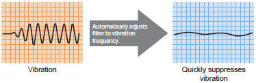
The vibration frequency is automatically measured to remove vibration. Even if the resonant frequency changes, realtime evaluation automatically follows the changes to reduce the effect of vibration due to low mechanical rigidity, such as for conveyer belts.
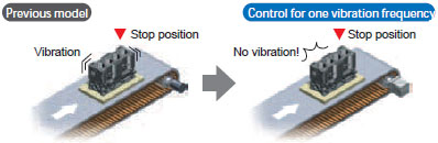
Mechanical vibration at the stop position caused by low mechanical rigidity can be suppressed by removing the vibration frequency.
last update: December 16, 2013
| Item | Specifications | ||
|---|---|---|---|
|
Ambient operating temperature Ambient operating humidity |
0 to 55 ºC, 90% max. (with no condensation) | ||
|
Ambient storage temperature Ambient storage humidity |
-20 to 65 ºC, 90% max. (with no condensation) | ||
| Storage and operating atmosphere |
No corrosive gasses, no dust, no iron dust, no exposure to moisture or cutting oil |
||
| Vibration resistance | 10 to 60 Hz; acceleration: 5.9 m/s2 (0.6 G) max. | ||
| Impact resistance | Acceleration of 19.6 m/s2 max. 3 times each in X, Y, and Z directions. | ||
| Insulation resistance |
Between power supply/power line terminals and frame ground: 0.5 MO. min. (at 500 VDC) |
||
| Dielectric strength |
Between power supply/power line terminals and frame ground: 1,500 VAC for 1 min at 50/60 Hz Between each control signal and frame ground: 500 VAC for 1 min |
||
| Altitude | 1,000 m above sea level max. (860 hp min.) | ||
| Degree of protection | Built into panel (IP10). | ||
|
International standards |
EC Directives |
EMC Directive |
EN 55011 class A group 1 EN 61000-6-2 |
|
Low Voltage Directive |
EN 50178 | ||
| UL standards | UL 508C | ||
| cUL standards | cUL C22.2 No.14 | ||
|
Korean Radio Regulations (KC) |
Certified | ||
| Item | Servo Drive model | ||
|---|---|---|---|
| R7D-BPA5L | R7D-BP01L | R7D-BP02L | |
| Continuous output current (rms) | 1.0 A | 1.6 A | 2.5 A |
| Momentary maximum output current (rms) | 3.3 A | 5.1 A | 7.5 A |
| Power supply capacity | 0.16 KVA | 0.25 KVA | 0.42 KVA |
| Input power supply voltage (main circuit) | Single-phase 100 to 115 VAC (85 to 127 V), 50/60 Hz | ||
| Input power supply current (rms) (main circuit) | 1.4 A | 2.2 A | 3.7 A |
| Heat generated (main circuit) | 12 W | 16 W | 22 W |
| Control method | All-digital servo | ||
| Inverter method | IGBT-driven PWM method | ||
| PWM frequency | 12 kHz | 6 kHz | |
| Maximum response frequency (command pulses) | Line drive: 500 kpps, Open collector: 200 kpps | ||
| Weight | 0.35 kg | 0.42 kg | |
| Applicable motor capacity | 50 W | 100 W | 200 W |
| Item | Servo Drive model | |||
|---|---|---|---|---|
| R7D-BP01H | R7D-BP02HH | R7D-BP02H | R7D-BP04H | |
| Continuous output current (rms) | 1.0 A | 1.6 A | 1.6 A | 2.5 A |
| Momentary maximum output current (rms) | 3.3 A | 4.9 A | 4.9 A | 7.8 A |
| Power supply capacity |
0.27 KVA (0.30 KVA) * |
0.35 KVA | 0.42 KVA |
0.69 KVA (0.77 KVA) * |
| Input power supply voltage (main circuit) |
Both single-phase and three-phase 200 to 240 VAC (170 to 264 V), 50/60 Hz |
|||
|
Input power supply current (rms) (main circuit) |
0.7 A (1.5 A) * |
1.6 A | 1.1 A |
1.8 A (3.5 A) * |
| Heat generated (main circuit) | 14 W | 16 W | 20 W | 26W |
| Control method | All-digital servo | |||
| Inverter method | IGBT-driven PWM method | |||
| PWM frequency | 12 kHz | 6 kHz | ||
|
Maximum response frequency (command pulses) |
Line drive: 500 kpps, Open collector: 200 kpps | |||
| Weight | 0.35 kg | 0.42 kg | 0.35 kg | 0.42 kg |
| Applicable motor capacity | 100 W | 200 W | 200 W | 400 W |
* Values inside parentheses ( ) are for single-phase 200-V use.
| Item | Specifications | ||
|---|---|---|---|
|
Ambient operating temperature Ambient operating humidity |
0 to 40 ºC, 85% max. (with no condensation) | ||
|
Ambient storage temperature Ambient storage humidity |
- 20 to 65 ºC, 85% max. (with no condensation) | ||
| Storage and operating atmosphere | No corrosive gases | ||
| Vibration resistance | 49 m/s2 max. in the X, Y, and Z directions | ||
| Impact resistance | Acceleration of 98 m/s2 max. 3 times each in the X, Y, and Z directions | ||
| Insulation resistance | 20 MO min. at 500 VDC between the power terminals and FG terminal | ||
| Dielectric strength |
1,500 VAC (50 or 60 Hz) for 1 minute between the power terminals and FG terminal |
||
| Operating position | Any direction | ||
| Insulation class | Type B | ||
| Construction | Totally-enclosed, self-cooling | ||
| Degree of protection | IP65 (excluding the through-shaft portion) | ||
| Vibration class | V-15 | ||
| Mounting method | Flange-mounting | ||
|
International standards |
EC Directives |
Low Voltage Directive |
IEC 60034-5:2001 |
| UL standards | UL 1004 File No. E179189 | ||
| cUL standards | cUL 22.2, No.100 | ||
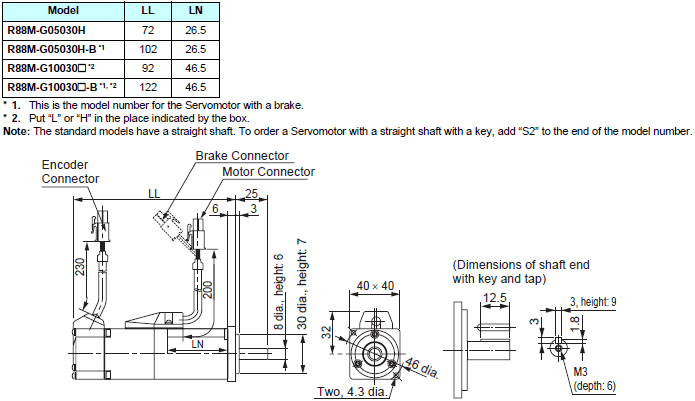
| Item | Unit | R88M-G05030H | R88M-G10030L | R88M-G20030L | |
|---|---|---|---|---|---|
| Rated output *1 | W | 50 | 100 | 200 | |
| Rated torque *1 | Nm | 0.16 | 0.32 | 0.64 | |
| Rated rotation speed | r/min | 3000 | |||
| Max. rotation speed | r/min | 5000 | |||
| Max. momentary torque *1 | Nm | 0.48 | 0.95 | 1.78 | |
| Rated current *1 | A (rms) | 1.1 | 1.7 | 2.5 | |
| Max. momentary current *1 | A (rms) | 3.4 | 5.1 | 7.6 | |
| Rotor inertia | kg·m2 | 2.5 × 10⁻⁶ | 5.1 × 10⁻⁶ | 1.4 × 10⁻⁵ | |
| Applicable load inertia | --- | 30 times rotor inertia max. | |||
| Power rate *1 | kW/s | 10.4 | 20.1 | 30.3 | |
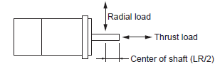
| Allowable radial load *2 | N | 68 | 68 | 245 | |
| Allowable thrust load *2 | N | 58 | 58 | 98 | |
| Weight | Without brake | kg | 0.3 | 0.5 | 0.8 |
| With brake | kg | 0.5 | 0.7 | 1.3 | |
| Radiation shield dimensions (material) | --- | 100 × 80 × t10 (Al) | 130 × 120 × t12 (Al) | ||
|
Brake specifications |
Brake inertia | kg·m2 | 2.0 × 10⁻⁷ | 2.0 × 10⁻⁷ | 1.8 × 10⁻⁶ |
| Excitation voltage *3 | V | 24 VDC ± 10% | |||
|
Power consumption (at 20 ºC) |
W | 7 | 7 | 9 | |
|
Current consumption (at 20 ºC) |
A | 0.3 | 0.3 | 0.36 | |
| Static friction torque | Nm | 0.29 min. | 0.29 min. | 1.27 min. | |
| Attraction time *4 | ms | 35 max. | 35 max. | 50 max. | |
| Release time *4 | ms | 20 max. | 20 max. | 15 max. | |
| Backlash | ± 1 º | ||||
|
Allowable work per braking operation |
J | 39.2 | 39.2 | 137 | |
| Allowable total work | J | 4.9 × 10³ | 4.9 × 10³ | 44.1 × 10³ | |
|
Allowable angular acceleration |
rad/s2 |
30,000 max. (Speed of 2,800 r/min minimum must not be stopped in less than 10 ms) |
|||
| Brake life | --- | 10,000,000 operations min. | |||
| Rating | --- | Continuous | |||
| Insulation class | --- | Type F | |||
| Item | Unit |
R88M- G05030H |
R88M- G10030H |
R88M- G20030H |
R88M- G40030H |
|
|---|---|---|---|---|---|---|
| Rated output *1 | W | 50 | 100 | 200 | 400 | |
| Rated torque *1 | Nm | 0.16 | 0.32 | 0.64 | 1.3 | |
| Rated rotation speed | r/min | 3000 | ||||
| Max. rotation speed | r/min | 5000 | ||||
| Max. momentary torque *1 | N·Em | 0.48 | 0.95 | 1.78 | 3.60 | |
| Rated current *1 | A (rms) | 1.1 | 1.1 | 1.6 | 2.6 | |
| Max. momentary current *1 | A (rms) | 3.4 | 3.4 | 4.9 | 7.9 | |
| Rotor inertia | kg·m 2 | 2.5 × 10⁻⁶ | 5.1 × 10⁻⁶ | 1.4 × 10⁻⁵ | 2.6 × 10⁻⁵ | |
| Applicable load inertia | --- | 30 times rotor inertia max. | ||||
| Power rate *1 | kW/s | 10.4 | 20.1 | 30.3 | 62.5 | |
| Allowable radial load *2 | N | 68 | 68 | 245 | 245 | |
| Allowable thrust load *2 | N | 58 | 58 | 98 | 98 | |
| Weight | Without brake | kg | 0.3 | 0.5 | 0.8 | 1.2 |
| With brake | kg | 0.5 | 0.7 | 1.3 | 1.7 | |
|
Radiation shield dimensions (material) |
--- | 100 × 80 × t10 (Al) | 130 × 120 × t12 (Al) | |||
|
Brake specifi- cations |
Brake inertia | kg·m 2 | 2.0 × 10⁻⁷ | 2.0 × 10⁻⁷ | 1.8 × 10⁻⁶ | 7.5 × 10⁻⁶ |
| Excitation voltage *3 | V | 24 VDC ± 10% | ||||
|
Power consumption (at 20 ºC) |
W | 7 | 7 | 9 | 9 | |
|
Current consumption (at 20 ºC) |
A | 0.30 | 0.30 | 0.36 | 0.36 | |
| Static friction torque | Nm | 0.29 min. | 0.29 min. | 1.27 min. | 1.27 min. | |
| Attraction time *4 | ms | 35 max. | 35 max. | 50 max. | 50 max. | |
| Release time *4 | ms | 20 max. | 20 max. | 15 max. | 15 max. | |
| Backlash | ± 1 º | |||||
|
Allowable work per braking operation |
J | 39.2 | 39.2 | 137 | 196 | |
| Allowable total work | J | 4.9 × 10³ | 4.9 × 10³ | 44.1 × 10³ | 147 × 103 | |
|
Allowable angular acceleration |
rad/s2 |
30,000 max. (Speed of 2,800 r/min minimum must not be stopped in less than 10 ms) |
||||
| Brake life | --- | 10,000,000 operations min. | ||||
| Rating | --- | Continuous | ||||
| Insulation class | --- | Type F | ||||
| Item | Unit | R88M-GP10030L | R88M-GP20030L | |
|---|---|---|---|---|
| Rated output *1 | W | 100 | 200 | |
| Rated torque *1 | Nm | 0.32 | 0.64 | |
| Rated rotation speed | r/min | 3000 | ||
| Max. rotation speed | r/min | 5000 | ||
| Max. momentary torque *1 | Nm | 0.85 | 1.86 | |
| Rated current *1 | A(rms) | 1.6 | 2.5 | |
| Max. momentary current *1 | A(0-p) | 6.9 | 10.5 | |
| Rotor inertia | kg·m 2 | 9.0 × 10⁻⁶ | 3.4 × 10⁻⁵ | |
| Applicable load inertia | --- | 20 times rotor inertia max. | ||
| Power rate *1 | kW/s | 11.4 | 12.0 | |
| Allowable radial load *2 | N | 68 | 245 | |
| Allowable thrust load *2 | N | 58 | 98 | |
| Weight | Without brake | kg | 0.65 | 1.3 |
| With brake | kg | 0.90 | 2.0 | |
|
Radiation shield dimensions (material) |
--- | 130 × 120 × t10 (Al) | 170 × 160 × t12 (Al) | |
|
Brake specifica- tions |
Brake inertia | kg·m 2 | 3.0 × 10⁻⁶ | 9.0 × 10⁻⁶ |
| Excitation voltage *3 | V | 24 VDC ± 10% | ||
|
Power consumption (at 20 ºC) |
W | 7 | 10 | |
|
Current consumption (at 20 ºC) |
A | 0.29 | 0.41 | |
| Static friction torque | Nm | 0.29 min. | 1.27 min. | |
| Attraction time *4 | ms | 50 max. | 60 max. | |
| Release time *4 | ms | 15 max. | 15 max. | |
| Backlash | ± 1 º | |||
|
Allowable work per braking operation |
J | 137 | 196 | |
| Allowable total work | J | 44.1 × 10³ | 147 × 103 | |
|
Allowable angular acceleration |
rad/s2 |
10,000 max. (Speed of 950 r/min minimum must not be stopped in less than 10 ms) |
||
| Brake life | --- | 10,000,000 operations min. | ||
| Rating | --- | Continuous | ||
| Insulation class | --- | Type F | ||
| Item | Unit | R88M-GP10030H | R88M-GP20030H | R88M-GP40030H | |
|---|---|---|---|---|---|
| Rated output *1 | W | 100 | 200 | 400 | |
| Rated torque *1 | Nm | 0.32 | 0.64 | 1.3 | |
| Rated rotation speed | r/min | 3000 | |||
| Max. rotation speed | r/min | 5000 | |||
| Max. momentary torque *1 | Nm | 0.90 | 1.82 | 3.60 | |
| Rated current *1 | A(rms) | 1.0 | 1.6 | 4.4 | |
| Max. momentary current *1 | A(0-p) | 4.3 | 6.8 | 18.6 | |
| Rotor inertia | kg·m 2 | 9.0 × 10⁻⁶ | 3.4 × 10⁻⁵ | 6.4 × 10⁻⁵ | |
| Applicable load inertia | --- | 20 times rotor inertia max. | |||
| Power rate *1 | kW/s | 11.4 | 11.8 | 25.5 | |
| Allowable radial load *2 | N | 68 | 245 | 245 | |
| Allowable thrust load *2 | N | 58 | 98 | 98 | |
| Weight | Without brake | kg | 0.7 | 1.3 | 1.8 |
| With brake | kg | 0.9 | 2.0 | 2.5 | |
|
Radiation shield dimensions (material) |
--- | 130 × 120 × t10 (Al) | 170 × 160 × t12 (Al) | ||
|
Brake specifica- tions |
Brake inertia | kg·m 2 | 3.0 × 10⁻⁶ | 9.0 × 10⁻⁶ | 9.0 × 10⁻⁶ |
| Excitation voltage *3 | V | 24 VDC ± 10% | |||
|
Power consumption (at 20 ºC) |
W | 7 | 10 | 10 | |
|
Current consumption (at 20 ºC) |
A | 0.29 | 0.41 | 0.41 | |
| Static friction torque | Nm | 0.29 min. | 1.27 min. | 1.27 min. | |
| Attraction time *4 | ms | 50 max. | 60 max. | 60 max. | |
| Release time*4 | ms | 15 max. | 15 max. | 15 max. | |
| Backlash | ± 1 º | ||||
|
Allowable work per braking operation |
J | 137 | 196 | 196 | |
| Allowable total work | J | 44.1 × 10³ | 147 × 103 | 147 × 103 | |
|
Allowable angular acceleration |
rad/s2 |
10,000 max. (Speed of 950 r/min minimum must not be stopped in less than 10 ms) |
|||
| Brake life | --- | 10,000,000 operations min. | |||
| Rating | --- | Continuous | |||
| Insulation class | --- | Type F | |||
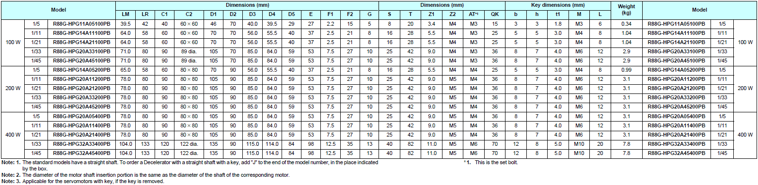
|
Model (R88G-) |
Rated speed |
Rated torque |
Ra- tio |
Maxi- mum mo- men- tary speed |
Maxi- mum mo- men- tary torque |
Decel- erator inertia |
Al- lowable radial load |
Al- lowable thrust load |
Weight | ||
|---|---|---|---|---|---|---|---|---|---|---|---|
| r/min | Nm | % | r/min | Nm | kg·m2 | N | N | kg | |||
|
50 W |
1/5 | HPG11A05100B | 600 | 0.60 | 75 | 1000 | 1.80 | 5.00× 10⁻⁷ | 135 | 538 | 0.29 |
| 1/9 | HPG11A09050B | 333 | 1.17 | 81 | 555 | 3.51 | 3.00× 10⁻⁷ | 161 | 642 | 0.29 | |
| 1/21 | HPG14A21100B | 143 | 2.18 | 65 | 238 | 6.54 | 5.00× 10⁻⁶ | 340 | 1358 | 1.04 | |
| 1/33 | HPG14A33050B | 91 | 3.73 | 71 | 151 | 11.2 | 4.40× 10⁻⁶ | 389 | 1555 | 1.04 | |
| 1/45 | HPG14A45050B | 67 | 5.09 | 71 | 111 | 15.2 | 4.40× 10⁻⁶ | 427 | 1707 | 1.04 | |
|
100 W |
1/5 | HPG11A05100B | 600 | 1.37 | 86 | 1000 | 4.07 | 5.00× 10⁻⁷ | 135 | 538 | 0.29 |
| 1/11 | HPG14A11100B | 273 | 2.63 | 75 | 454 | 7.80 | 6.00× 10⁻⁶ | 280 | 1119 | 1.04 | |
| 1/21 | HPG14A21100B | 143 | 5.40 | 80 | 238 | 16.0 | 5.00× 10⁻⁶ | 340 | 1358 | 1.04 | |
| 1/33 | HPG20A33100B | 91 | 6.91 | 65 | 151 | 20.5 | 6.50× 10⁻⁵ | 916 | 3226 | 2.4 | |
| 1/45 | HPG20A45100B | 67 | 9.42 | 65 | 111 | 27.9 | 6.50× 10⁻⁵ | 1006 | 3541 | 2.4 | |
|
200 W |
1/5 | HPG14A05200B | 600 | 2.49 | 78 | 1000 | 7.44 | 2.07× 10⁻⁵ | 221 | 883 | 1.02 |
| 1/11 | HPG14A11200B | 273 | 6.01 | 85 | 454 | 17.9 | 1.93× 10⁻⁵ | 280 | 1119 | 1.09 | |
| 1/21 | HPG20A21200B | 143 | 10.2 | 76 | 238 | 30.6 | 4.90× 10⁻⁵ | 800 | 2817 | 2.9 | |
| 1/33 | HPG20A33200B | 91 | 17.0 | 81 | 151 | 50.8 | 4.50× 10⁻⁵ | 916 | 3226 | 2.9 | |
| 1/45 | HPG20A45200B | 67 | 23.2 | 81 | 111 | 69.3 | 4.50× 10⁻⁵ | 1006 | 3541 | 2.9 | |
|
400 W |
1/5 | HPG14A05400B | 600 | 5.66 | 87 | 1000 | 16.5 | 2.07× 10⁻⁵ | 221 | 883 | 1.09 |
| 1/11 | HPG20A11400B | 273 | 11.7 | 82 | 454 | 34.2 | 5.70× 10⁻⁵ | 659 | 2320 | 2.9 | |
| 1/21 | HPG20A21400B | 143 | 23.5 | 86 | 238 | 68.8 | 4.90× 10⁻⁵ | 800 | 2547 | 2.9 | |
| 1/33 | HPG32A33400B | 91 | 34.7 | 81 | 151 | 101.7 | 6.20× 10⁻⁵ | 1565 | 6240 | 7.5 | |
| 1/45 | HPG32A45400B | 67 | 47.4 | 81 | 111 | 138.6 | 6.10× 10⁻⁵ | 1718 | 6848 | 7.5 | |
|
Model (R88G-) |
Rated speed |
Rated torque |
Ra- tio |
Maxi- mum mo- men- tary speed |
Maxi- mum mo- men- tary torque |
Decel- erator inertia |
Al- lowable radial load |
Al- lowable thrust load |
Weight | ||
|---|---|---|---|---|---|---|---|---|---|---|---|
| r/min | Nm | % | r/min | Nm | kg·m2 | N | N | kg | |||
|
100 W |
1/5 | HPG11A05100PB | 600 | 1.37 | 85 | 1000 | 3.84 (3.63) | 5.00× 10⁻⁷ | 135 | 538 | 0.34 |
| 1/11 | HPG14A11100PB | 273 | 2.63 | 75 | 454 | 7.39 (6.98) | 6.00× 10⁻⁶ | 280 | 1119 | 1.04 | |
| 1/21 | HPG14A21100PB | 143 | 5.40 | 80 | 238 | 15.2 (14.6) | 5.00× 10⁻⁶ | 340 | 1358 | 1.04 | |
| 1/33 | HPG20A33100PB | 91 | 6.91 | 65 | 151 | 19.4 (18.3) | 4.50× 10⁻⁵ | 916 | 3226 | 2.9 | |
| 1/45 | HPG20A45100PB | 67 | 9.42 | 65 | 111 | 26.5 (25.0) | 4.50× 10⁻⁵ | 1006 | 3541 | 2.9 | |
|
200 W |
1/5 | HPG14A05200PB | 600 | 2.49 | 78 | 1000 | 7.09 | 2.07× 10⁻⁵ | 221 | 883 | 0.99 |
| 1/11 | HPG20A11200PB | 273 | 4.75 | 68 | 454 | 13.5 | 5.80× 10⁻⁵ | 659 | 2320 | 3.1 | |
| 1/21 | HPG20A21200PB | 143 | 10.2 | 76 | 238 | 29.2 | 4.90× 10⁻⁵ | 800 | 2817 | 3.1 | |
| 1/33 | HPG20A33200PB | 91 | 17.0 | 81 | 151 | 48.5 | 4.50× 10⁻⁵ | 916 | 3226 | 3.1 | |
| 1/45 | HPG20A45200PB | 67 | 23.2 | 81 | 111 | 66.1 | 4.50× 10⁻⁵ | 1006 | 3541 | 3.1 | |
|
400 W |
1/5 | HPG20A05400PB | 600 | 4.67 | 72 | 1000 | 12.9 | 7.10× 10⁻⁵ | 520 | 1832 | 3.1 |
| 1/11 | HPG20A11400PB | 273 | 11.7 | 82 | 454 | 32.4 | 5.80× 10⁻⁵ | 659 | 2320 | 3.1 | |
| 1/21 | HPG20A21400PB | 143 | 23.5 | 86 | 238 | 65.2 | 4.90× 10⁻⁵ | 800 | 2817 | 3.1 | |
| 1/33 | HPG32A33400PB | 91 | 34.7 | 81 | 151 | 96.2 | 2.80× 10⁻⁴ | 1565 | 6240 | 7.8 | |
| 1/45 | HPG32A45400PB | 67 | 47.4 | 81 | 111 | 131.2 | 2.80× 10⁻⁴ | 1718 | 6848 | 7.8 | |
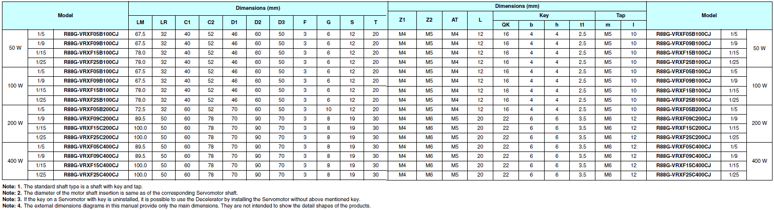
|
Model (R88G-) |
Rated speed |
Rated torque |
Ra- tio |
Maxi- mum mo- men- tary speed |
Maxi- mum mo- men- tary torque |
Decel- erator inertia |
Al- lowable radial load |
Al- lowable thrust load |
Weight | ||
|---|---|---|---|---|---|---|---|---|---|---|---|
| r/min | Nm | % | r/min | Nm | kg·m2 | N | N | kg | |||
|
50 W |
1/5 | VRXF05B100CJ | 600 | 0.66 | 82 | 1000 | 1.97 | 6.04× 10⁻⁶ | 392 | 196 | 0.55 |
| 1/9 | VRXF09B100CJ | 333 | 1.18 | 82 | 556 | 3.54 | 4.97× 10⁻⁶ | 441 | 220 | 0.55 | |
| 1/15 | VRXF15B100CJ | 200 | 1.85 | 77 | 333 | 5.54 | 5.26× 10⁻⁶ | 588 | 294 | 0.70 | |
| 1/25 | VRXF25B100CJ | 120 | 3.08 | 77 | 200 | 9.24 | 5.14× 10⁻⁶ | 686 | 343 | 0.70 | |
|
100 W |
1/5 | VRXF05B100CJ | 600 | 1.44 | 90 | 1000 | 4.28 | 6.04× 10⁻⁶ | 392 | 196 | 0.55 |
| 1/9 | VRXF09B100CJ | 333 | 2.59 | 90 | 556 | 7.70 | 4.97× 10⁻⁶ | 441 | 220 | 0.55 | |
| 1/15 | VRXF15B100CJ | 200 | 4.13 | 86 | 333 | 12.26 | 5.26× 10⁻⁶ | 588 | 294 | 0.70 | |
| 1/25 | VRXF25B100CJ | 120 | 6.88 | 86 | 200 | 20.43 | 5.14× 10⁻⁶ | 686 | 343 | 0.70 | |
|
200 W |
1/5 | VRXF05B200CJ | 600 | 2.94 | 92 | 1000 | 8.19 | 1.47× 10⁻⁵ | 392 | 196 | 0.72 |
| 1/9 | VRXF09C200CJ | 333 | 4.78 | 83 | 556 | 13.30 | 2.37× 10⁻⁵ | 931 | 465 | 1.70 | |
| 1/15 | VRXF15C200CJ | 200 | 8.26 | 86 | 333 | 22.96 | 3.02× 10⁻⁵ | 1176 | 588 | 2.10 | |
| 1/25 | VRXF25C200CJ | 120 | 13.76 | 86 | 200 | 38.27 | 2.93× 10⁻⁵ | 1323 | 661 | 2.10 | |
|
400 W |
1/5 | VRXF05C400CJ | 600 | 5.72 | 88 | 1000 | 15.84 | 3.7× 10⁻⁵ | 784 | 392 | 1.70 |
| 1/9 | VRXF09C400CJ | 333 | 10.30 | 88 | 556 | 28.51 | 2.37× 10⁻⁵ | 931 | 465 | 1.70 | |
| 1/15 | VRXF15C400CJ | 200 | 17.36 | 89 | 333 | 48.06 | 3.02× 10⁻⁵ | 1176 | 588 | 2.10 | |
| 1/25 | VRXF25C400CJ | 120 | 28.93 | 89 | 200 | 80.10 | 2.93× 10⁻⁵ | 1323 | 661 | 2.10 | |
Note: 1. The value given for the Decelerator inertia is the Servomotor shaft conversion value.
Note: 2. The protective structure rating of the Servomotor combined with the Decelerator is IP44.
(Excluding Decelerator and Servomotor connecting parts.)
Note: 3. The value given for the allowable radial load is the value at the center of the shaft (T/2).
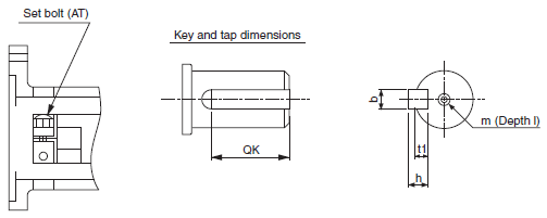
Note: 4. The standard shaft type is a shaft with key and tap. (The key is temporarily assembled to the shaft.)
Note: 5. Take care so that the surface temperature of the Decelerator does not exceed 90ºC.
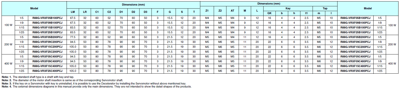
|
Model (R88G-) |
Rated speed |
Rated torque |
Ra- tio |
Maxi- mum mo- men- tary speed |
Maxi- mum mo- men- tary torque |
Decel- erator inertia |
Al- lowable radial load |
Al- lowable thrust load |
Weight | ||
|---|---|---|---|---|---|---|---|---|---|---|---|
| r/min | Nm | % | r/min | Nm | kg·m2 | N | N | kg | |||
|
100 W |
1/5 | VRXF05B100PCJ | 600 | 1.44 | 90 | 1000 |
4.05 (3.83) |
6.00× 10⁻⁶ | 392 | 196 | 0.70 |
| 1/9 | VRXF09B100PCJ | 333 | 2.59 | 90 | 556 |
7.29 (6.89) |
5.00× 10⁻⁶ | 441 | 220 | 0.70 | |
| 1/15 | VRXF15B100PCJ | 200 | 4.13 | 86 | 333 |
11.61 (10.97) |
5.70× 10⁻⁶ | 588 | 294 | 0.90 | |
| 1/25 | VRXF25B100PCJ | 120 | 6.88 | 86 | 200 |
19.35 (18.28) |
5.50× 10⁻⁶ | 686 | 343 | 0.90 | |
|
200 W |
1/5 | VRXF05B200PCJ | 600 | 2.94 | 92 | 1000 |
8.37 (8.56) |
1.50× 10⁻⁵ | 392 | 196 | 0.90 |
| 1/9 | VRXF09C200PCJ | 333 | 4.78 | 83 | 556 |
13.60 (13.89) |
2.70× 10⁻⁵ | 931 | 465 | 2.00 | |
| 1/15 | VRXF15C200PCJ | 200 | 8.26 | 86 | 333 |
23.48 (23.99) |
3.02× 10⁻⁵ | 1176 | 588 | 2.40 | |
| 1/25 | VRXF25C200PCJ | 120 | 13.76 | 86 | 200 |
39.13 (39.99) |
2.90× 10⁻⁵ | 1323 | 661 | 2.40 | |
|
400 W |
1/5 | VRXF05C400PCJ | 600 | 5.72 | 88 | 1000 | 15.84 | 3.70× 10⁻⁵ | 784 | 392 | 2.00 |
| 1/9 | VRXF09C400PCJ | 333 | 10.30 | 88 | 556 | 28.51 | 2.70× 10⁻⁵ | 931 | 465 | 2.00 | |
| 1/15 | VRXF15C400PCJ | 200 | 17.36 | 89 | 333 | 48.06 | 3.02× 10⁻⁵ | 1176 | 588 | 2.40 | |
| 1/25 | VRXF25C400PCJ | 120 | 28.93 | 89 | 200 | 80.10 | 2.90× 10⁻⁵ | 1323 | 661 | 2.40 | |
Note: 1. The values inside parentheses ( ) are those when using a 100-V motor.
Note: 2. The value given for the Decelerator inertia is the Servomotor shaft conversion value.
Note: 3. The protective structure rating of the Servomotor combined with the Decelerator is IP44.
(Excluding Decelerator and Servomotor connecting parts.)
Note: 4. The value given for the allowable radial load is the value at the center of the shaft (T/2).
Note: 5. The standard shaft type is a shaft with key and tap. (The key is temporarily assembled to the shaft.)
Note: 6. Take care so that the surface temperature of the Decelerator does not exceed 90ºC.
| Item | Specifications |
|---|---|
| Encoder system | Optical encoder (incremental encoder) |
| No. of output pulses | Phases A and B: 2,500 pulses/rotation, Phase Z: 1 pulse/rotation |
| Power supply voltage | 5 V ± 5% |
| Power supply current | 180 mA (max.) |
| Output signals | +S, - S |
| Output interface | EIA RS-485 compliance |
| Duplex serial communications data |
| Model |
Re- sistance |
Nominal capacity |
Regeneration absorption for 120 ºC temperature rise |
Heat radiation condition |
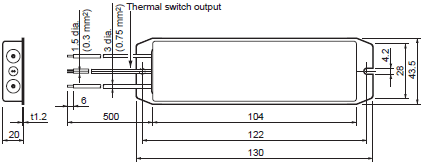
Thermal switch output specifications |
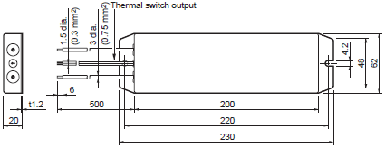
|---|---|---|---|---|---|
| R88A-RR08050S | 50 O | 80 W | 20 W |
Aluminum 250 × 250, Thickness: 3.0 |
Operating temperature: 150 ºC ±5%, NC contact, Rated output: 30 VDC, 50 mA max. |
| R88A-RR080100S | 100 O | 80 W | 20 W |
Aluminum 250 × 250, Thickness: 3.0 |
Operating temperature: 150 ºC ±5%, NC contact, Rated output: 30 VDC, 50 mA max. |
| R88A-RR22047S1 | 47 O | 220 W | 70 W |
Aluminum 350 × 350, Thickness: 3.0 |
Operating temperature: 170 ºC ±5%, NC contact, Rated output: 3 A |
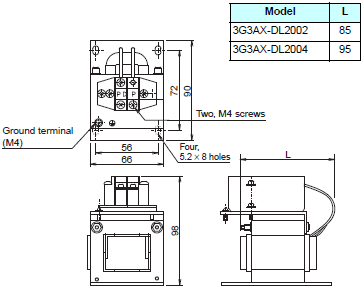
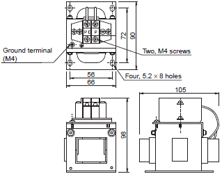
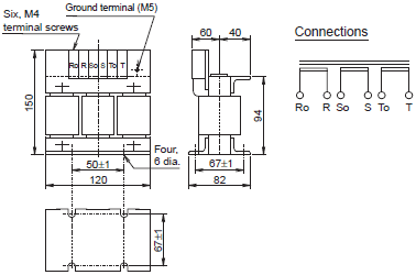
| Reactor type | Specifications | |||
|---|---|---|---|---|
| Model | Rated current (A) | Inductance (mH) | Weight (kg) | |
| Single-phase Reactors | 3G3AX-DL2002 | 1.6 A | 21.4 mH | 0.8 kg |
| 3G3AX-DL2004 | 3.2 A | 10.7 mH | 1.0 kg | |
| 3G3AX-DL2007 | 6.1 A | 6.75 mH | 1.3 kg | |
| Three-phase Reactor | 3G3AX-AL2025 | 10 A | 2.8 mH | 2.8 kg |
| Item | Specifications |
|---|---|
|
Operating ambient temperature Operating ambient humidity |
0 to 55 ºC 90% max. (with no condensation) |
|
Storage ambient temperature Storage ambient humidity |
- 20 to 80 ºC 90% max. (with no condensation) |
| Storage and operating atmosphere | No corrosive gases |
| Vibration resistance | 5.9 m/s2 max. |
| Item | Specifications | |
|---|---|---|
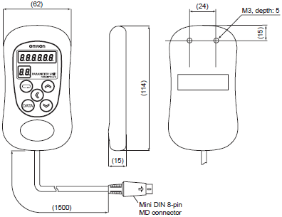
| Type | Hand-held | |
| Cable length | 1.5 m | |
| Connectors | Mini DIN 8-pin MD connector | |
| Display | 7-segment LED | |
| External dimensions | 62 × 114 × 15 mm (W × H × D) | |
| Weight | Approx. 0.1 kg (including cable that is provided) | |
| Communications specifications | Standard | RS-232 |
| Communications method | Asynchronous (ASYNC) | |
| Baud rate | 9,600 bps | |
| Start bits | 1 bit | |
| Data | 8 bits | |
| Parity | None | |
| Stop bits | 1 bit | |
last update: October 2, 2017
(Unit: mm)
50 W/100 W/200 W
R7D-BPA5L
R7D-BP01L
R7D-BP01H
R7D-BP02H
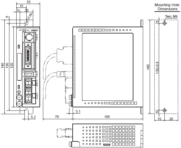
200 W/400 W
R7D-BP02L
R7D-BP02HH
R7D-BP04H

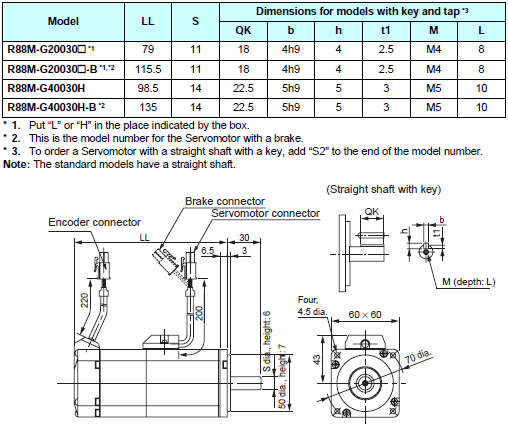
50 W/100 W
[Without brake]
R88M-G05030H (-S2), R88M-G10030L (-S2), R88M-G10030H (-S2)
[With brake]
R88M-G05030H (-S2), R88M-G10030L (-S2), R88M-G10030H (-S2)
200 W/400 W
[Without brake]
R88M-G20030L (-S2), R88M-G20030H (-S2), R88M-G40030H (-S2)
[With brake]
R88M-G20030L-B (S2), R88M-G20030H-B (S2), R88M-G40030H-B (S2)
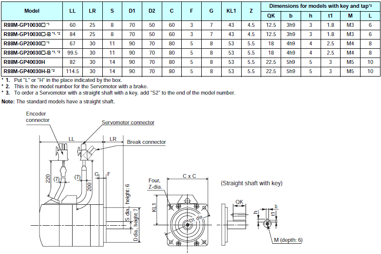
3,000-r/min servomotors (50 to 400 W)
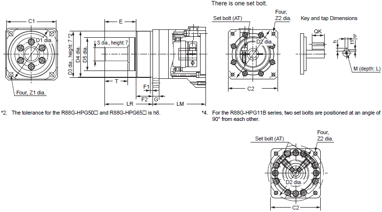
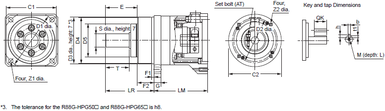
Outline Drawings 1
Outline Drawings 2
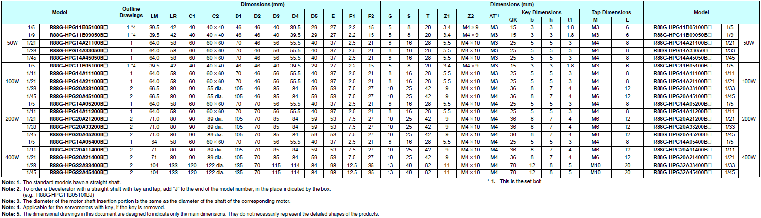
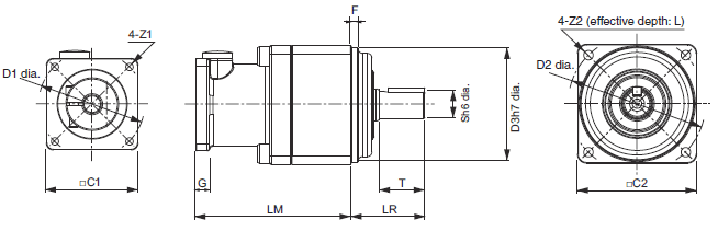
3,000-r/min servomotors (100 to 400 W)
Outline Drawings
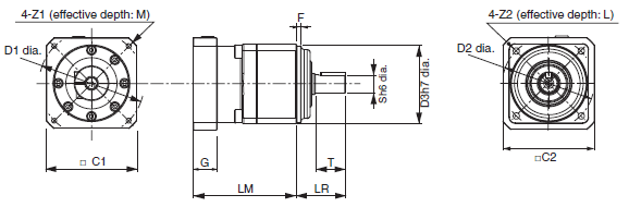
3,000-r/min servomotors (50 to 400 W)
Outline Drawings

3,000-r/min servomotors (100 to 400 W)
Outline Drawings
R88A-PR02G
R7A-DIN01B
R88A-RR22047S1
R88A-RR08050S
R88A-RR080100S
3G3AX-DL2002
3G3AX-DL2004
3G3AX-DL2007
3G3AX-AL2025
last update: October 2, 2017