Automation Systems
  Motion & Power Solutions
  Safety, Vision and IDENT
  Sensing Solutions
  Control Components
  Switching & Accessories
  Switchgear and Trolley Systems
  Process Weighing
  LED Lighting
  Omron
Omron
 Mitsubishi
 Delta
Delta
 Autonics
 Inno
Inno
 Panasonic
 Novotechnik
 Orientalmotor
 Microscan
 IPA
IPA
 Technomech
 Intech
 Honeywell
 IOT & Traceability
 Project & Panel Engg.
 Application Case Studies
 Solutions by Industry
 Solutions by Process
 Solutions by Product
 Youtube Videos
 Corporate Information
 Company Profile
 Quality Policy
 Mission Statement
 Chairman's Message
 Intech Group Companies

Compact Industrial SCARA
Compact Industrial Robot with light weight space saving arm. Its high speed operation is best suited for pick and place, labelling, tracking


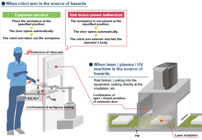
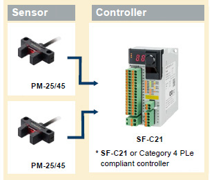
A Category 3 PLd Safety System can be built by using Category 4 PLe compliant controllers together with our sensors
*1 Safety-related parts of control systems, Part 1: General principles for design
*2 Conformed from December 2021 production.
 |
[Precautions when using as Category 3 PLd] |
[Required conditions]
| 1. | The source of hazards is located inside the machine and may cause hazards to nearby people. |
|---|---|
| 2. | The equipment is classified as Category 3 PLd or lower. |
| 3. | The source of hazards is isolated only by the automatic door. |
* The product can be used safely when all of the above conditions 1 through 3 are satisfied!
* There are cases where you can use it under other conditions.
|
| * | Be sure to read the Cautions For Use when using for safety applications. |
|---|
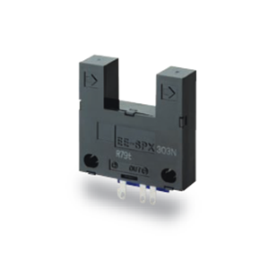
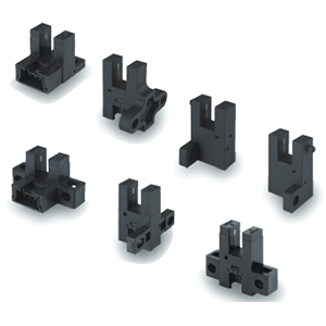
All models are standardly equipped with the following protection circuits in their compact bodies. These protection circuits minimize the possibility of sensor malfunctions caused by erroneous wiring.
①.Reverse supply polarity protection circuit
②.Reverse output polarity protection circuit
③.Output short-circuit protection circuit
*As of April 2017, in-company survey.
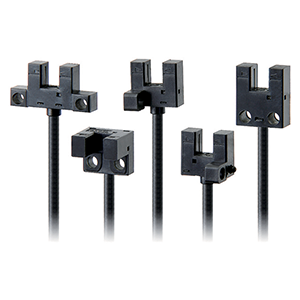
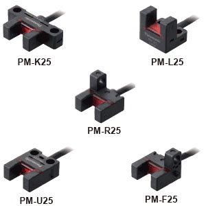
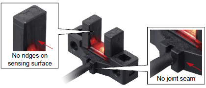
Our original integrated molding method has eliminated grooves and gaps on the sensing surface and main body, thus reducing the possibility of malfunctions caused by splashing water or dust.
|
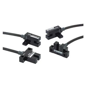
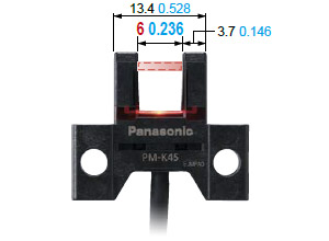
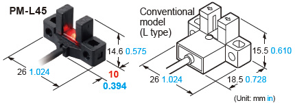
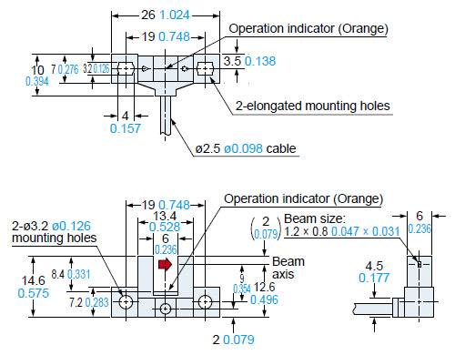
The beam emitting and receiving sections are 0.5 mm 0.02 in thinner than those on our conventional models while their external dimensions are the same. As a result, the distance between the beam emitting point and receiving point increased by 1 mm 0.039 in. The wider distance means less possibility of collision between the sensing section and sensing object.
|
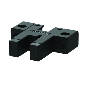
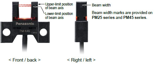
The upper-limit and lower-limit positions of beam can be visually confirmed from the front, back, right and left sides of the sensor unit. This allows easy adjustment of the position of sensing object.
|
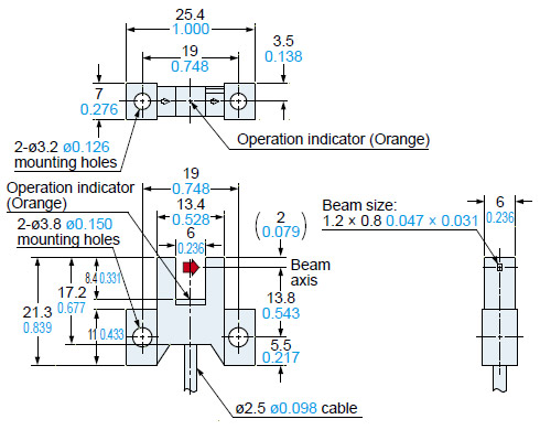
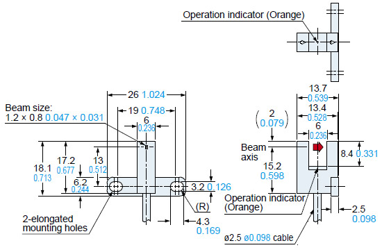
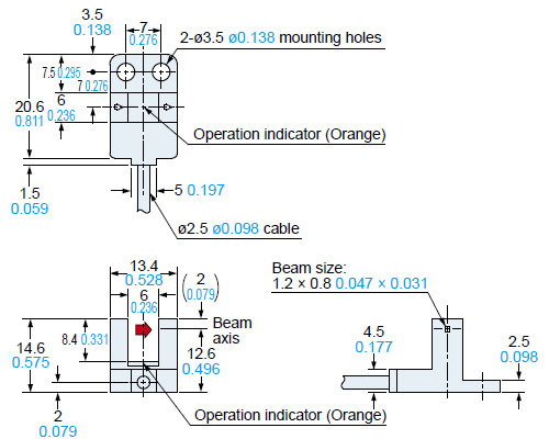
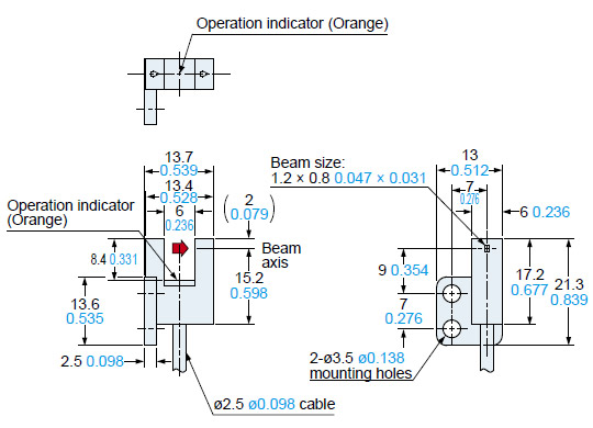
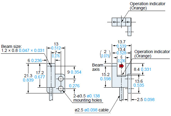
The large operation indicator (orange) lights up when the beam enters. The indicator is easy to see from above and from the sides.
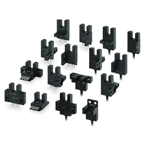
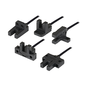
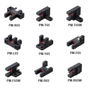
All new models require significantly less mounting space than our conventional models when mounted with the same pitch.
What's more, the new models can directly replace our conventional models currently in use.
|
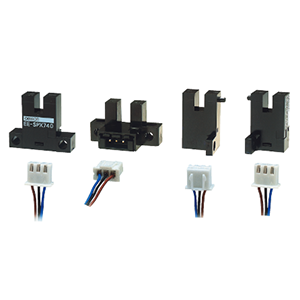
The sensor unit can be installed with two M3 screws.
(M3 screws and washers are not included.)
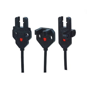
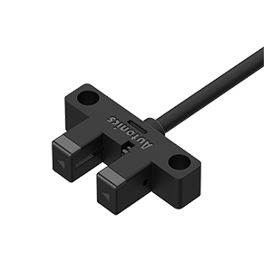
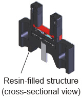
The sections where stress concentrates, such as the connecting section of the cable and internal circuit, are covered with a resin. This helps prevent malfunctions caused by vibrations and impacts.
|
Sensor
|
Sensor
|
Sensor
|
Sensor
|
Sensor
|
Sensor
|