
 |
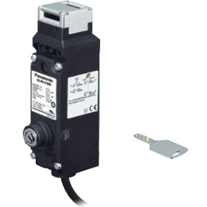
The safety door switch with key SG-B2 series locks and unlocks doors with keys. |
Hazards of the system and robot are isolated by the safety guard. The worker uses the key to unlock the door and disables the system from starting unexpectedly, then removes the key and brings it into the hazardous area. The system remains off until the worker walks out the door and locks the door with the key. This enables the worker carrying the key to work safely in the hazardous area.
|
Hazards of the system and robot are isolated by the safety guard. When a worker needs to work inside the hazardous area for maintenance, the worker unlocks the safety guard using a key, disables the system from starting (1), removes the key and brings it into the hazardous area, and then changes the operation mode of each system to maintenance mode (2). While the worker is carrying out maintenance work in the hazardous area, the safety guard cannot be locked and the system cannot be turned on. This enables the worker to work safely in the hazardous area.
|
Since doors are locked and unlocked with a key, there is no need to supply power to the safety door switch.
Head removal detection function is employed in the SG-B2. With this innovative function, the monitor circuit (41-42) turns off when the head is removed from the switch, such as when removing the head to change the head direction.
With the head installed on the switch, monitor circuits 41-42 and 51-52 operate in synchronization while the key locks / unlocks the actuator.
When the head is removed, 41-42 turns off and 51-52 turns on.
This disagreement is detected by the head removal detection function.
|
|
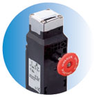 |
Models with a rear unlocking button allow the door to be unlocked from the inside in the event a worker is left in the hazardous area. |
Safety controllers incorporate safety circuit logic that complies with ISO 13849-1 PLe requirements, making it easy to build safety circuits that support a variety of equipment without the need to create programs.
|
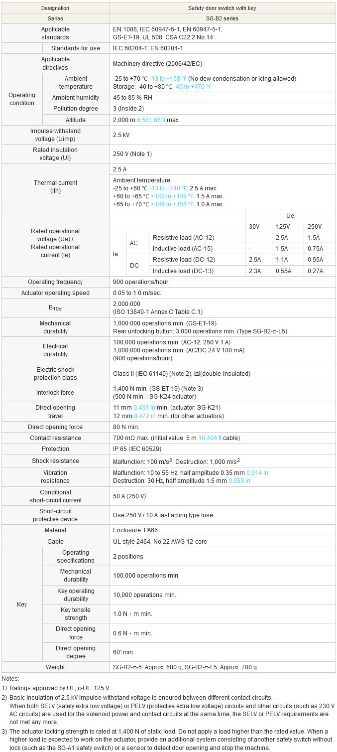
Door switch
|
|
Notes:
| 1) | Plug the unused actuator entry slot using the plug supplied with the switch. |
|---|---|
| 2) | When mounting the safety switch, be sure to conform to the mounting hole dimensions and secure in place with four screws. |
Door switch (rear unlocking button type)
|
As shown in the figure on the right, the mounting reference position of the actuator when inserted in the safety switch is: |
 |
Straight actuator
|
Right-angle actuator (SG-K22)
|
Straight actuator with rubber bushings
|
Note:The actuator stop is used to adjust the actuator position. Remove the actuator stop after the actuator position is mounted.
| * | Mounting pitch is set to 12 mm 0.472 in in factory. When setting the mounting pitch to 20 mm 0.787 in, widen the pitch of rubber cushions to 20 mm 0.787 in. |
|---|---|
| * | The actuator has movement flexibility to the directions shown in (B). |
Right-angle actuator with rubber bushings
|
Note:The actuator stop is used to adjust the actuator position. Remove the actuator stop after the actuator position is mounted.
| * | When the mounting pitch is 12 mm 0.472 in (factory setting), the actuator has movement flexibility to the directions shown in (A) and (B). |
|---|---|
| * | When the mounting pitch is 20 mm 0.787 in, the actuator has movement flexibility to the directions shown in (B). Side the rubber cushions together with the screws. |
Slide actuator
|
Horizontal / Vertical angle adjustable actuators
|
The orientation of adjustment of angle adjustable (vertical / horizontal) actuators is determined by the position in which the orienting insert (white plastic) is installed on the back of the actuator.
Install the insert according to the desired orientation of adjustment.
Exercise care not to lose the orienting insert. The actuator will not operate properly without the orienting insert.
Padlock hasp (Optional)
|
Mounting plate (Optional)
|
Rear unlocking button kit for a frame (Optional)
|
|
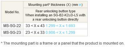
| Example: | When mounted on a □30 mm □1.181 in frame using the mounting plate above MS-SG-21, select MS-SG-22 since the mounting part thickness (X) is 40 (X = 10 + 30 = 40) 1.575 (X = 0.394 + 1.181 = 1.575). For more information about selecting a back manual unlocking button kit for a frame, see the following table: |
|---|
| TITLE | DOCUMENT TYPE | SIZE |
| SG-B2 | Catalog | 3681 KB |
|---|---|---|
| SG-B2 | Manual | 1738 KB |
| SG-B2 | Manual | 2180 KB |
| SG-K21S [Actuator] | Manual | 356 KB |
